EP0444902B2 - Bearbeitungssystem für Linsenränder - Google Patents
Bearbeitungssystem für Linsenränder Download PDFInfo
- Publication number
- EP0444902B2 EP0444902B2 EP91301594A EP91301594A EP0444902B2 EP 0444902 B2 EP0444902 B2 EP 0444902B2 EP 91301594 A EP91301594 A EP 91301594A EP 91301594 A EP91301594 A EP 91301594A EP 0444902 B2 EP0444902 B2 EP 0444902B2
- Authority
- EP
- European Patent Office
- Prior art keywords
- lens
- edging
- workpiece
- edging tool
- tool
- Prior art date
- Legal status (The legal status is an assumption and is not a legal conclusion. Google has not performed a legal analysis and makes no representation as to the accuracy of the status listed.)
- Expired - Lifetime
Links
Images


Classifications
-
- G—PHYSICS
- G05—CONTROLLING; REGULATING
- G05B—CONTROL OR REGULATING SYSTEMS IN GENERAL; FUNCTIONAL ELEMENTS OF SUCH SYSTEMS; MONITORING OR TESTING ARRANGEMENTS FOR SUCH SYSTEMS OR ELEMENTS
- G05B19/00—Program-control systems
- G05B19/02—Program-control systems electric
- G05B19/18—Numerical control [NC], i.e. automatically operating machines, in particular machine tools, e.g. in a manufacturing environment, so as to execute positioning, movement or co-ordinated operations by means of program data in numerical form
- G05B19/182—Numerical control [NC], i.e. automatically operating machines, in particular machine tools, e.g. in a manufacturing environment, so as to execute positioning, movement or co-ordinated operations by means of program data in numerical form characterised by the machine tool function, e.g. thread cutting, cam making, tool direction control
- G05B19/184—Generation of cam-like surfaces
-
- B—PERFORMING OPERATIONS; TRANSPORTING
- B24—GRINDING; POLISHING
- B24B—MACHINES, DEVICES, OR PROCESSES FOR GRINDING OR POLISHING; DRESSING OR CONDITIONING OF ABRADING SURFACES; FEEDING OF GRINDING, POLISHING, OR LAPPING AGENTS
- B24B49/00—Measuring or gauging equipment for controlling the feed movement of the grinding tool or work; Arrangements of indicating or measuring equipment, e.g. for indicating the start of the grinding operation
- B24B49/02—Measuring or gauging equipment for controlling the feed movement of the grinding tool or work; Arrangements of indicating or measuring equipment, e.g. for indicating the start of the grinding operation according to the instantaneous size and required size of the workpiece acted upon, the measuring or gauging being continuous or intermittent
-
- B—PERFORMING OPERATIONS; TRANSPORTING
- B24—GRINDING; POLISHING
- B24B—MACHINES, DEVICES, OR PROCESSES FOR GRINDING OR POLISHING; DRESSING OR CONDITIONING OF ABRADING SURFACES; FEEDING OF GRINDING, POLISHING, OR LAPPING AGENTS
- B24B9/00—Machines or devices designed for grinding edges or bevels on work or for removing burrs; Accessories therefor
- B24B9/02—Machines or devices designed for grinding edges or bevels on work or for removing burrs; Accessories therefor characterised by a special design with respect to properties of materials specific to articles to be ground
- B24B9/06—Machines or devices designed for grinding edges or bevels on work or for removing burrs; Accessories therefor characterised by a special design with respect to properties of materials specific to articles to be ground of non-metallic inorganic material, e.g. stone, ceramics, porcelain
- B24B9/08—Machines or devices designed for grinding edges or bevels on work or for removing burrs; Accessories therefor characterised by a special design with respect to properties of materials specific to articles to be ground of non-metallic inorganic material, e.g. stone, ceramics, porcelain of glass
- B24B9/14—Machines or devices designed for grinding edges or bevels on work or for removing burrs; Accessories therefor characterised by a special design with respect to properties of materials specific to articles to be ground of non-metallic inorganic material, e.g. stone, ceramics, porcelain of glass of optical work, e.g. lenses, prisms
- B24B9/148—Machines or devices designed for grinding edges or bevels on work or for removing burrs; Accessories therefor characterised by a special design with respect to properties of materials specific to articles to be ground of non-metallic inorganic material, e.g. stone, ceramics, porcelain of glass of optical work, e.g. lenses, prisms electrically, e.g. numerically, controlled
Definitions
- the invention lies in the field of lens edging machines for shaping lenses from lens blanks, and relates to an apparatus and a method for such purposes.
- Lens edging machines are well-known in the art, one type being described, for example, in U.S. Patent No. 4,870,784 to Ramos et al.
- a lens is formed from a blank having a certain curvature in accordance with the desired optical focusing power.
- the curvature of an ophthalmic lens provides a corrective focusing power.
- the lens curvature for dark glasses or sun glasses typically provides no corrective focusing power.
- the lens Having formed the lens blank with the desired curvature, the lens must be “cut” out of the blank in a shape which fits into the frame of the glasses. This is accomplished by “edging", or grinding the edges of the lens with an edging tool such as a grinding wheel until the desired lens shape is reached.
- the edging process may be performed by a lens edging machine of the type described in the above-referenced patent to Ramos et al. which uses a groove in the grinding wheel to bevel the lens edge.
- a lens edging machine typically employed to make non-ophthalmic lenses uses an apex in its grinding wheel to bevel the lens edge.
- the bevel on the lens edge enables the lens to fit tightly into the frames of the eye glasses or sun glasses.
- Both types of lens edging machines rotate the lens blank with respect to the grinding wheel. Simultaneously, as the lens blank is rotated, the machine changes the displacement between the center of the lens blank and the wheel in accordance with the shape of the lens to be formed from the lens blank.
- the displacement is changed by means of a cam having the desired lens shape which rotates with the lens blank against a stationary surface, as is well-known in the art.
- a cam having the desired lens shape which rotates with the lens blank against a stationary surface.
- One problem with this feature is that the machine operation must be halted and the cam changed each time a different lens shape is to be made. After the lens has been formed from the lens blank, it is beveled, as mentioned above. The lens edge is then smoothed or polished to complete the process.
- Another problem is that the rate at which the lens edge is ground must be slow enough to avoid damaging the glass lens material. If in an attempt to boost productivity the grinding wheel speed and/or the lens rotation speed is increased to the point at which sparking is observed during the edge grinding process, the glass material is damaged and rendered useless for high-quality eye-wear. Even if sparking or combustion of small glass particles is not observed, the lens surface may be too rough to be acceptable as a result of grinding the edge too fast. For these reasons, the rate at which the lens is ground is necessarily slow in order to avoid any risk of damaging the glass lens material. The disadvantage is that the slow production rate drives up the cost of producing lenses.
- Computers have been employed to assist the lens edging process, as disclosed in the above-referenced patent to Ramos et al. Specifically, a computer is used to position the lens edge directly over the beveling groove in the Ramos et al. grinding wheel in accordance with the lens size, different sized lenses requiring different positions relative to the groove. Also, the computer in the Ramos et al. patent controls the sequencing of operations.
- US-A-4 233 784 relates to an apparatus/a method according to the preamble of claim 1/claim 12.
- Patent specification EP-A-0 092 364 discloses a method and apparatus which avoids the need to use a cam follower in edging a lens blank.
- This specification discloses a method and apparatus in which digital data pertaining to a lens shape is obtained from a lens template or from a frame in which the lens is to be mounted. From this data what are called edge-driver files are produced and stored in a memory associated with a computer.
- the edge-driver file corresponding to a desired lens shape is used to control the lens edging procedure by which the lens blank is ground to shape.
- the file holds data relating to the rotational angle of the lens blank and the radial positioning of the blank at each angular position.
- lens trajectory for the lens blank or workpiece that is to be shaped which incorporates data relating to a succession of corresponding lens rotational angles and lens radii and a succession of axial positions.
- the lens trajectory can also incorporate parameters providing for the bevelling of the lens edge on an apex portion of the edging tool.
- a pre-programmable lens edging apparatus embodying the invention which grinds and bevels the lens edge under the control of a microprocessor responding to a lens edge shape programmed into memory.
- the system holds the lens blank by a robot-like arm controlled by the microprocessor.
- the rotation of the lens by the arm as well as the motion of the arm with respect to the grinding wheel determines the lens shape and size in accordance with the lens edge shape programmed into memory.
- the lens edge shape and size are easily changed by simply directing the microprocessor to a different lens edge shape in the memory, thus saving the time required to replace the cam in the prior lens edging machines.
- the described apparatus includes a sensor for measuring the lens size in a self-corrective feedback loop through the microprocessor which automatically compensates for wear shrinkage of the grinding wheel.
- the self-corrective feedback loop permits the machine to use the same grinding wheel and wear it down almost to a nub without suffering appreciable change in lens size, depending upon the frequency at which the lens size is monitored.
- the practice of the invention also includes a method for distributing wear across at least near the entire surface of the grinding wheel, whereby the lens blank continually moves axially across the surface of the grinding wheel during substantially the entire lens edge grinding operation so as to uniformly distribute wear across the surface of the grinding wheel.
- This uniform wear process avoids the formation of voids or grooves in the grinding wheel, which in prior machines have required elimination by dressing the wheel frequently.
- the wheel does not need to be changed until it has been completely worn away, and by virtue of the uniform wear process need not be dressed, thus eliminating the frequent interruptions required by frequent attention to maintenance of the grinding wheel in prior lens edging machines.
- the lens edge is beveled on a convex apex portion of the grinding wheel by successively rotating opposite sides of the lens edge against opposite sides of the grinding wheel apex.
- the rotational motion of the lens as well as the motion of the robot-like arm holding the lens is governed by the microprocessor in accordance with a trajectory stored in memory computed in accordance with the shape and curvature of the lens and the shape of the grinding wheel apex.
- the term "trajectory” refers to the simultaneous paths of (a) the rotation of the lens about a fixed center point on the lens, (b) the radial motion of the lens perpendicular to the rotational axis of the grinding wheel and (c) the transversal motion of the lens parallel to the rotational axis of the grinding wheel.
- Different beveling geometries may be programmed into memory for the same type of lens and the same beveling geometry may be programmed into memory for many different lenses.
- the motion of the lens or lens blank is divided into N points in time covering the entire lens edge grinding and beveling process, where N is on the order of 64,000, for example.
- N is on the order of 64,000, for example.
- the rate at which the lens is rotated against the grinding wheel, the rotational speed of the wheel, the velocity at which the lens is translated axially across the surface of the grinding wheel and the force with which the lens is held against the grinding wheel are each defined in memory for each one of the N points.
- the microprocessor requires a complete set of such definitions stored in memory for each different lens shape to be made.
- the set of definitions of the lens rotational rate, the grinding wheel speed, the axial lens feed velocity and the grinding pressure are optimized at each one of the N points to maximize lens grinding speed (productivity) to a rate slightly below that which would overheat the glass lens material.
- the optimum value for each parameter (rotational rate, speed, feed velocity and grinding pressure) is determined at each one of the N points in accordance with a trial and error method of the invention in which various combinations of all the parameters are tried at each one of the N points and the results stored in memory.
- the microprocessor systematically varies all the parameters (rate, speed, velocity and pressure) while monitoring a spark sensor positioned to detect overheating of the glass lens material.
- the microprocessor For each one of the N points in the motion of the lens, the microprocessor notes the value of all the parameters at the highest grinding wheel speed at which no overheating was detected by the sensor. The microprocessor stores the noted values in memory. After this process has been carried out at all N points, the trial and error process is complete, and the memory contains a set of optimum grinding parameters for the entire grinding process of a given lens shape. This set of parameters is then permanently stored (on hard disk or in read-only memory, for example) and reused over and over during the manufacture of lenses of the same design. The learning process merely requires a memory of sufficient capacity.
- the optimum speed at which the glass is removed from the lens is determined at least in part by the ability of the removed glass particles to take away heat from the workpiece or lens blank.
- rate of glass removal should be prevented from decreasing as the size of the workpiece (the lens blank) decreases during the grinding process.
- the trial and error learning method in many cases may progressively increase the grinding wheel speed as the size of the lens blank decreases during the grinding process.
- the set of optimum grinding parameters generated by the trial and error learning method will implement well-known principles of metal lathe techniques sometimes referred to as "constant surfacing".
- a lens edging apparatus comprising the features of claim 1.
- Claim 15 defines an apparatus for performing a method according to the second aspect of the invention.
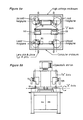
- FIG. 1a illustrates the basic steps in a lens edging process of the prior art.
- a grinding wheel 10 includes a cylinder portion 12 and an apex portion 14, both portions having concentric circular shapes as shown in Fig. 1b.
- the grinding wheel 10 is made of a diamond-like material.
- a lens blank 18 shown in Fig. 2a is ground along its edge 18 on the cylindrical portion 12 of Fig. 1a to form the lens 20 of Fig. 2b.
- the "left" corner 18a of the lens edge 18 is then ground on the "right" side 14a of the apex portion 14 and the "right” corner 18b of the lens edge 18 is ground on the "left" side 14b of the apex portion 14 to form beveled lens edge surfaces 22a and 22b, respectively.
- the geometry of the beveled surfaces 22a and 22b conforms to the design of the eye wear frame in which the lens 20 is to be mounted.
- the motion of the lens during the grinding process is governed by the motion of a rotating cam (not shown) against a stationary surface, the cam having the same shape as that of the lens 20 illustrated in Fig. 2b.
- the method and apparatus of the prior art suffered from a number of disadvantages as discussed previously herein, arising from the wearing away of the surface of the grinding wheel 10, the wearing away of the surface of the cam and the formation of voids in the surface of the grinding wheel 10 due to non-uniform wear, as well as the necessity of changing the cam each time a different lens design was to be followed.
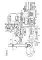
- Each lens blank is withdrawn from a carousel 26 containing many lens blanks by a servo-controlled hand 28 mounted on a servo-controlled arm 30 governed by an arm servo controller 32 controlled by a central microprocessor 34.
- the position of the rotating carousel 26 is controlled by the microprocessor 34 through a carousel rotation controller 25 using well-known digital servo control techniques.
- the hand 28 moves axially along the arm 30 so that it extends itself toward the carousel 26 (dashed-line position) and grabs the lens blank 16 by pressing opposing edges thereof between two fingers 34, 36.
- the finger 36 is movable toward the other finger 34 to clasp the lens 16 firmly.
- the hand 28 then withdraws up the arm 30 and the arm 30 rotates about a pivot 38 to the solid line position.
- the hand 28 then moves axially along the arm 30 to insert the lens between opposing driver cups 40, 42 (Fig. 4) mounted on rotating spindles 44, 46.
- the spindles 44, 46 are supported on opposing spars 48, 50 of a lens servo arm 52 governed by a lens servo controller 54 under control of the microprocessor 34.
- the lens servo controller 54 causes the opposing spars 48, 50 to travel toward one another to grasp the lens blank 16 between the two driver cups 40, 42, as shown in Fig. 4.
- the microprocessor 34 then commands the lens servo controller 54 to move the arm 52 toward the grinding wheel 10 and hold the edge of the lens blank 16 against the wheel 10 and to rotate the spindles 44, 46 by means of a spindle motor 58 controlled by the lens servo controller 54.
- the lens servo controller 54 varies the distance R of the center of the lens blank 16 (i.e., the axis of the spindles 44, 46) from the axis of the grinding wheel 10 as the lens blank rotates about the axis of the spindles 44, 46 so as to achieve the desired lens edge contour or shape.
- the lens servo controller 54 does this under control of the microprocessor 34 in accordance with a lens trajectory table stored in a lens shape trajectory memory 60.
- the lens trajectory table defines the distance r between the lens blank center and the grinding wheel 10 for each incremental rotational position ⁇ of the lens blank 16 about the axis of the spindles 44, 46 in accordance with the shape of the lens to be formed.
- the microprocessor 34 computes from the data stored in the lens shape trajectory memory 60 servo control signals using a servo controller program stored in a lens servo controller program memory 62. Generating the servo controller program is conventional in the art. The microprocessor 34 transmits the control signals thus generated in a succession which determines the sequence of the lens edge grinding steps.
- the lens edge is smoothed by the lens servo arm holding the corner 18a of the lens edge 18 against a rotating break-edge wheel 61.
- the lens shape trajectory memory 60 may contain a large selection of different trajectory tables for manufacturing different lenses with different edge contours. Thus, the lens design may be quickly changed by directing the microprocessor 34 to a different table in the memory 60, a significant advantage.
- the solution has been to frequently replace the grinding wheel 10 to minimize the growth in lens size as successive lenses are edged.
- This problem is now solved by using a size probe 64 connected through probe output circuits 66 to the microprocessor 34.
- the probe 64 is of the type manufactured by, for example, Renishaw Metrology Ltd., Gloucester, England.
- the lens servo arm 52 rotates the lens to a predetermined rotational position ⁇ and then moves the lens 20 edgewise toward the probe 64.
- the microprocessor 34 notes the position of the lens servo arm 52 at the point when the probe 64 first senses contact with the lens edge.
- This position indicates the radius r of the lens 20 at the rotational position ⁇ .
- the correct position may be readily determined from the desired lens edge contour.
- the microprocessor 34 compares the actual position and the correct position to compute an error.
- the microprocessor 34 compensates for this error by adjusting (decreasing) the distance between the next lens to be edged and the axis of the grinding wheel 10.
- the microprocessor 34 adjusts the trajectory of the lens for the entire edging process to bring it closer to the rotational axis of the wheel 10 by an amount equal to the computed position error. This feature will be described below herein.
- the grinding wheel 10 may be allowed to wear down almost to its axle during the edging of successive lenses without creating errors in lens dimensions as long as the lens radius is monitored sufficiently frequently.
- the lens servo arm 52 must perform a complex task by rotating the lens blank 16 while varying its displacement from the grinding wheel 10 in accordance with the desired lens shape while at the same time translating the lens axially across the surface of the wheel 10 in a continuous motion. This task is even more complex as the lens is beveled on the apex portion 14 of the wheel 10, as will be discussed below herein.
- the preferred practice of the invention requires the same microprocessor 34 to control the simultaneous grinding of a pair of lenses by a pair of grinding wheels 10, 11 using a pair of lens servo arms 52, 53.
- a pair of lens servo arms 52, 53 For each one of the two grinding wheels 10, 11, there is an unload arm 30 (as in Fig. 3) and a load arm 31, an unload carousel 26 (as in Fig. 3) and a load carousel 27.
- the unload arm 30 picks a lens blank out of the unload carousel 26 and gives it to the lens servo arm 52 for edging.
- the load arm 31 takes the lens from the lens servo arm 52 and places it in the load carousel 27. Each carousel is rotated to position the present the next slot in the carousel to the corresponding load or unload arm for the next cycle.
- the microprocessor 34 is programmed to operate the carousels and the load and unload arms so that as one finished lens is being placed into the unload carousel, the next lens blank is being taken from the load carousel, so that there is no wasted motion.
- One advantage is that the same cycle may be used to simultaneously produce a pair of lenses to be inserted into the same eye wear frame, so as to enhance the probability that each pair of lenses is closely matched.
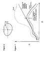
- Fig. 6 illustrates an exemplary lens edge shape in polar coordinates.
- the radius r in Fig. 6 corresponds to the distance r in Fig. 4 between the center of the lens 20 (the axis of the spindles 44, 46) and the surface of the grinding wheel 10.
- the center of the lens is the point around which the lens 20 rotates during the edging process.
- the distance R in Fig. 4 is the displacement between the center of the lens and the center of the grinding wheel 10.
- the difference between r and R is the radius of the grinding wheel 10.
- the solid line curve of Fig. 7 is a graph of R as a function of the lens rotation angle ⁇ corresponding to the polar coordinate plot of Fig. 6.
- the solid line curve is the trajectory defined in the data stored in the lens trajectory memory 60 governing the motion of the lens blank 16 over the cylindrical portion 14 (only) of the grinding wheel 10.
- the trajectory of the lens 20 during the beveling operation is more complex and depends upon the slope of the apex portion 14 of the grinding wheel 10 as well as the curvature of the lens 20 itself. Assuming that the lens shape depicted in the polar plot of Fig. 6 has no curvature --is perfectly flat-- the lens trajectory during the beveling operation may be obtained by superimposing the dashed sloped line of Fig. 7 onto the solid line curve and adding the two together. The resulting complex lens trajectory (dotted line) describes the lens trajectory relative to the grinding wheel 10 during beveling as the lens is translated axially across the surface of the apex portion 14 at a constant speed for uniformly distributing wear across the entire surface of the grinding wheel 10.
- the dotted line curve describes that portion of the lens trajectory in which the lens climbs up one side of the apex 14 and then descends down the other side so as to uniformly distribute wear across the surface of the apex portion 14.
- the dotted line curve of Fig. 7 corresponds to the data stored in the memory 60 for the beveling portion of the lens edging process.
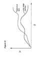
- the lens trajectory is even more complex during beveling because the lens typically has a spherical curvature (as depicted in the side view of the lens 20 in Fig. 1a).
- This complex lens trajectory may be obtained in the graph of Fig. 8 by summing the solid line curve defining the lens edge shape and the non-linear dashed line curve.
- the shape of the non-linear dashed line curve of Fig. 8 is dictated by the curvature of the lens and the included angle ⁇ of the apex portion 14 of the grinding wheel 10.
- the resulting lens trajectory during beveling is not illustrated for the more complex case of Fig. 8, but is theoretically obtained by adding the two curves of Fig. 8 together.
- the distance R between the lens 20 and the center of the apex 14 the depth to which the lens edge is beveled may be varied as desired.
- a more practical method for obtaining the lens trajectory during beveling is to calculate it using spherical trigonometry, in accordance with well-known principles.
- a computer program for doing this is attached hereto as an Appendix.
- Such a computer program can be performed by the microprocessor 34 and may be stored in a lens motion program memory 64.
- Such a program merely requires the user to input the lens design data including the lens shape (as represented by the polar plot of Fig. 6), the lens curvature (visible in the side view of the lens of Fig. 1a for example) and the included angle ⁇ of the apex portion 14 of the grinding wheel 10.
- Such input data may be stored or entered at a peripheral device 66 illustrated in Fig. 3.
- the peripheral device may be a memory or a communication device such as a modem.
- a new lens design may be input from a distant remote location via modem (66) and the entire lens motion quickly and automatically calculated by the microprocessor 34 using the lens motion program in the memory 66.
- the resulting lens trajectory table is stored by the microprocessor 34 in the memory 60 along with corresponding tables for other lens designs.
- the entire procedure of changing or updating lens designs requires virtually no human presence at the system of Fig. 3, a significant advantage.
- the difference between R and r is the radius of the grinding wheel 10, which decreases as the wheel wears down.
- the self-correcting feedback method performed by the microprocessor 34 periodically compares the ideal lens radius at some predetermined lens rotation angle ⁇ against the correct radius at that angle as determined from the graph of Fig. 6. Any difference indicates the amount by which the grinding wheel radius has decreased from wear.
- the microprocessor 34 simply changes the trajectory by subtracting from all values of R in the graph of Fig. 7 (for example) the detected difference between the actual and ideal lens radius at some predetermined angle ⁇ .
- the result is illustrated by the dash-dotted line of Fig. 7.
- the displacement E between the solid line and the dash-dotted line in Fig. 7 is the error or difference detected by the microprocessor 34 between the ideal and actual lens radii.
- the microprocessor 34 maintains the lens radius r as a function of lens rotation angle ⁇ at the correct value by decreasing R as necessary.
- All parameters governing the lens edging process are defined in a table stored in the memory 60. Already discussed herein are the lens shaping parameters r and ⁇ as well as the continuous axial feed velocity required to achieve uniform wear of the edging tool. Remaining parameters include the rotational rate of the lens (d ⁇ /dt), the grinding wheel speed and the force with which the lens edge is pressed against the wheel.
- the motion of the lens is divided into N discrete segments.
- N 64,000, although it should be recognized that the skilled worker may choose any suitable value for N.
- These segments may be thought of as N points in time t 0 , t 1 , t 2 , ..., t N covering the entire duration of the edging process.
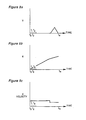
- the displacement Y of the center of the lens from the axis of the wheel 10 as a function of time is illustrated in Fig. 9a.
- the triangular hump in Fig. 9a corresponds to the beveling portion of the process.
- Fig. 9b is contemporary with Fig.
- FIG. 9a illustrates the position X of the center of the lens along the axis of the grinding wheel as a function of time.
- the feed velocity (dX/dt) of the lens is smaller during the beveling portion of the process. This is illustrated in Fig. 9c.
- dX/dt feed velocity
- Fig.'s 9a, 9b and 9c correspond to the lens trajectory indicated in Fig. 4 in which the lens blank 16 constantly travels axially across the grinding wheel 10. All of the parameters mentioned previously may be plotted in like fashion. Such plots are divided into N points (in the manner of Fig.'s 9a, 9b and 9c) and digitized to represent the data stored in the memory 60.
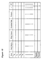
- Fig. 10 illustrates the format of the data stored in the memory 60 in a table.
- the table of Fig. 10 defines the lens axial feed velocity, the wheel speed, the lens rotational rate, the grinding force, the displacement r and the lens rotation angle ⁇ .
- the microprocessor 34 fetches from the table of Fig. 10 (stored in the memory 60) the corresponding value for each one of the foregoing parameters and determines therefrom any changes in the servo control signals it sends to the lens servo controller 54, the grinding wheel motor 70 and the lens rotation motor 58.
- the lens servo controller 54 by governing the motion of the lens servo arm 52, controls the rate of axial translation of the lens along the axis of the wheel 10, the rotation of the lens as well as the distance r of the center of the lens from the surface of the grinding wheel 10.
- the "optimum" set of values for all parameters at each one of the N points is defined as that set which results in the greatest productivity without harm to the glass lens material. Such harm is evidenced by visible sparking (combustion of glass particles) during edging or poor surface finish on the lens edge following the edging process.
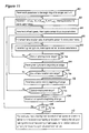
- the method for programming the memory 60 and operating the system of Fig. 3 with the optimum values of the parameters of the table of Fig. 10 begins with the preparatory learning steps illustrated in the flow diagram of Fig. 11. Essentially, the parameters are all varied at each one of the N points into which the process has been divided in the table of Fig. 10 and the combination of parameter values having the highest glass lens material removal rate by the grinding wheel without evidence of harm to the material is selected as the optimum set for that point in the process. This task is performed N times to find the optimum combination of parameter values at each one of the N points.
- this method employs a spark sensor 72 (such as an infrared sensor) illustrated in Fig. 3 positioned to sense any sparking of glass particles removed by the grinding wheel 10 from the lens blank 16.
- the microprocessor 34 causes the system to automatically and systematically step through all possible combinations of all the parameters of the table of Fig. 10 at each one of the N points in the lens edging process (blocks 80 through 108 of Fig. 11). For each combination of parameter values, the microprocessor 34 interrogates the spark sensor 72 to determine whether that combination is permissible. After all the data has been stored, the microprocessor 34 finds the highest permissible grinding wheel speed and stores it along with the values of the other parameters stored concurrently in the table of Fig. 10 in the memory 60 (block 110 of Fig. 11). The microprocessor 34 thus fills all entries in the table of Fig. 10 by performing the foregoing task for each one of the N points into which the lens edging and beveling process has been divided.
- the learning process begins by setting each of the parameters to the beginning of its range and initializing the index i to zero (block 80 of Fig. 11).
- the X i ,Y i position of the lens blank 16 is then incremented to the next (i + 1 st ) position and the microprocessor 34 interrogates the spark sensor 72 and stores the current value of all the parameters of the table of Fig. 10 if the spark sensor 72 does not detect overheating of the glass lens material (block 82 of Fig. 11).
- the wheel speed is then incremented and the microprocessor 34 repeats the same interrogation and storing task as before (block 84).
- the lens rotation rate is incremented and the microprocessor 34 repeats the same interrogation and storing tasks as before (block 86).
- the grinding force is incremented and the microprocessor 34 repeats the same interrogation and storing tasks as before (block 90).
- the step of block 90 is successively repeated in an inner loop until the grinding force reaches the end of its range (block 92) at which point it is reset to the beginning of its range (block 94).
- the step of block 86 is successively repeated in an outer loop, each such repetition including a complete cycling of the inner loop until the lens rotation rate reaches the end of its range (block 100) at which point it is reset to the beginning of its range (block 102).
- the step of block 84 is successively repeated, each such repetition including complete cycling of the inner and outer loops in the manner previously described until the wheel speed reaches the end of its range (block 104) at which point it is reset to the beginning of its range (block 106).
- the process returns to step of block 82 and repeats itself. Otherwise (YES branch of block 108), the microprocessor 34 begins analyzing the data stored in the previous steps (block 110). In the step of block 110, the microprocessor 34 reviews all of the combinations of parameters recorded for each one of the N locations X i ,Y i in the trajectory of the lens blank 16. At each location, the microprocessor determines which combination had the highest grinding wheel speed, and records that combination (only) in the table of Fig. 10 at the corresponding value of t i .
- Fig. 11 illustrates one of many possible trial and error learning processes which may be implemented.
- the optimum combination of parameter values is defined simply in terms of the greatest grinding wheel speed and a spark sensor is employed.
- a spark sensor is employed.
- another definition of the optimum combination of parameter values may be employed.
- a measurement of the surface finish may be substituted instead of the spark sensor 72.
- some of the foregoing parameters may be eliminated or other equivalent parameters substituted therefore.
- One advantage of the programmed learning process of Fig. 11 is that increasing the rate at which the grinding wheel 10 removes material from the glass lens blank 16 increases the rate at which heat is removed from the blank 16, so that the optimum upper limit for grinding speed may be much higher than expected.
- acceptable results characterized by an RMS surface finish of the lens edge of between 32 and 250 is achieved by grinding wheel speeds in the neighborhood of 2,500 RPM, a lens rotation rate of 20 RPM and an axial lens feed rate of 30 inches/minute.
- the included angle of the apex portion 14 of the wheel 10 is 113°.
- the microprocessor 34 is part of an AT computer system of the well-known type in which the microprocessor controls a 20 mega-byte hard disk memory 80 through a disk drive controller 82 and controls a monitor 84 through a video controller 86. Commands may be sent to the microprocessor by an AT keyboard terminal 88.
- the memories 60, 62 and 66 are all individual memory locations in the hard disk memory 80.
- An operator may use the keyboard terminal 88 to have the microprocessor 34 display on the monitor information regarding the lens edging process performed by the system of Fig. 3.
- the operator may use the keyboard terminal 88 to begin or interrupt or modify the process, for example to permit new lens design data to be recieved through the modem 68 and stored in the memory 80.
- the operator may also use the keyboard terminal 88 to command the microprocessor to begin the programmed learning process of Fig. 11.
- the process of Fig. 11 is implemented in a software program stored in the memory 80.
Landscapes
- Engineering & Computer Science (AREA)
- Mechanical Engineering (AREA)
- Inorganic Chemistry (AREA)
- Human Computer Interaction (AREA)
- General Physics & Mathematics (AREA)
- Automation & Control Theory (AREA)
- Chemical & Material Sciences (AREA)
- Ceramic Engineering (AREA)
- Manufacturing & Machinery (AREA)
- Physics & Mathematics (AREA)
- Grinding And Polishing Of Tertiary Curved Surfaces And Surfaces With Complex Shapes (AREA)
- Eyeglasses (AREA)
- Non-Portable Lighting Devices Or Systems Thereof (AREA)
- Wire Bonding (AREA)
- Optical Couplings Of Light Guides (AREA)
- Constituent Portions Of Griding Lathes, Driving, Sensing And Control (AREA)
Claims (15)
- Linsenrandschleifvorrichtung, umfassend:wobei der Mikroprozessor im Gebrauch bewirkt, dass das Linsenwerkstück gegen die Schleiffläche des Randschleifwerkzeugs gehalten wird, um der genannten Linsentrajektorie zu folgen, wobei der Kontaktpunkt zwischen der Linse und der Schleiffläche axial entlang dem Schleifwerkzeug gemäß den genannten gespeicherten Daten variiert.ein Randschleifwerkzeug, das um eine erste Achse drehbar ist und eine Schleiffläche (10) hat;ein Mittel (52) zum Halten eines zu gestaltenden Linsenwerkstücks (16), wobei das genannte Haltemittel die Aufgabe hat, das Linsenwerkstück um eine vorbestimmte Achse parallel zur genannten ersten Achse in eine Folge von Winkelpositionen zu drehen, und axial beweglich ist, um die axiale Position des Linsenwerkstücks relativ zum Randschleifwerkzeug zu verändern;ein Mittel (60) zum Speichern von Daten bezüglich der radialen Position des Linsenwerkstücks relativ zum Randschleifwerkzeug für jede der genannten Folge von Winkelpositionen;wobei das genannte Haltemittel (52) die Aufgabe hat, das Linsenwerkstück kontinuierlich entlang der genannten vorbestimmten Achse in einer geregelten axialen Geschwindigkeit und somit über die Schleiffläche des genannten Randschleifwerkzeugs zu bewegen;wobei das genannte Datenspeichermittel (60) die Aufgabe hat, Daten bezüglich der axialen Position des Linsenwerkstücks mit Bezug auf die genannte Folge von Winkelpositionen zu speichern, um eine Linsentrajektorie mit Bezug auf die Schleiffläche des Randschleifwerkzeugs zu errichten, umfassend eine Folge von Linsenrotationswinkeln, eine entsprechende Folge von Linsenradien und eine entsprechende Folge von axialen Positionen mit Bezug auf die Schleiffläche des Randschleifwerkzeugs; wobei das genannte Datenspeichermittel (60) außerdem die Aufgabe hat, Daten zu speichern, die die Geschwindigkeit definieren, mit der die Linse axial über die Fläche des Randschleifwerkzeugs für jeden Teil der Linsentrajektorie translatiert wird, wobei die genannte Geschwindigkeit über das genannte Randschleifwerkzeug nicht konstant ist;ein Antriebsmittel (54), das mit dem genannten Haltemittel verbunden ist, um die axialen, radialen und rotierenden Bewegungen des genannten Haltemittels zu steuern; undeinen programmierbaren Mikroprozessor (34), der auf die gespeicherten Daten im Zusammenhang mit den genannten winkligen, radialen und axialen Positionen und der Geschwindigkeit anspricht, um Steuersignale zu dem genannten Antriebsmittel zu senden, die von den gespeicherten Daten stammen, wobei die genannten Steuersignale die axiale, radiale und rotierende Bewegung des genannten Haltemittels steuern, um das Linsenwerkstück zu gestalten, während das Linsenwerkstück entlang der genannten vorbestimmten Achse und über die genannte Schleiffläche bewegt wird;
- Linsenrandschleifvorrichtung nach Anspruch 1, ferner umfassend einen Sensor (64) zum Messen eines radialen Parameters der gestalteten Linse, wobei der genannte Sensor mit dem genannten Mikroprozessor verbunden ist, um den Wert des gemessenen Radialparameters zu liefern, wobei der genannte Mikroprozessor die Aufgabe hat, einen Fehlerwert von dem genannten gemessenen Radialparameterwert und von einem entsprechenden Radialparameterwert von den gespeicherten Daten abzuleiten, und ferner die Aufgabe hat, den genannten Fehlerwert in die Ableitung der genannten Steuersignale einzubauen, um einen solchen Fehler bei der Gestaltung eines nachfolgenden Linsenwerkstücks zu reduzieren.
- Linsenrandschleifvorrichtung nach Anspruch 2, wobei der genannte Mikroprozessor die Aufgabe hat, Steuersignale zu erzeugen, die die genannte vorbestimmte Achse in einer berechneten radialen Entfernung von der genannten ersten Achse des genannten Randschleifwerkzeugs für jede der genannten Folge von Winkelpositionen positionieren, wobei der genannte Fehlerwert in jeder berechneten Entfernung eingeschlossen ist.
- Linsenrandschleifvorrichtung nach einem der vorherigen Ansprüche, wobei die genannten gespeicherten Daten die Form einer Tabelle mit N Orten haben, die jeweils eine Mehrzahl von Datenelementen enthalten, die wenigstens einen der folgenden Parameter einschließen:a) Translationsgeschwindigkeit des Linsenwerkstücks entlang der genannten vorbestimmten Achse,b) Rate der Winkelrotation des Linsenwerkstücks,c) Geschwindigkeit des Randschleifwerkzeugs undd) die Kraft, mit der das Linsenwerkstück gegen das Randschleifwerkzeug gehalten wird.
- Linsenrandschleifvorrichtung nach Anspruch 4, wobei die Drehzahl des Randschleifwerkzeugs ein gespeicherter Parameter ist, und wobei an jedem Ort in der Tabelle die höchste Drehzahl in Übereinstimmung mit den anderen Betriebsparametern am gleichen Ort in der Tabelle ist, wo keine Überhitzung in einem Versuch-und-Irrtum-Test eines gestalteten Linsenwerkstücks beobachtet wurde, und wobei
das genannte Randschleifwerkzeug mit dem genannten Mikroprozessor verbunden ist, der auch Geschwindigkeitsregelsignale für das genannte Randschleifen sendet. - Linsenrandschleifvorrichtung nach Anspruch 4, wobei die Drehzahl des Randschleifwerkzeugs ein gespeicherter Parameter und die höchste Geschwindigkeit in Übereinstimmung mit den anderen Betriebsparametern ist, wo keine Überhitzung in einem Versuch-und-Irrtum-Test eines gestalteten Linsenwerkstücks beobachtet wurde, und wobei
das genannte Randschleifwerkzeug mit dem genannten Mikroprozessor verbunden ist, der Steuersignale für das genannte Randschleifwerkzeug sendet. - Linsenrandschleifvorrichtung nach einem der vorherigen Ansprüche, ferner umfassend ein erstes (27) und ein zweites (26) Karussell zum Aufbewahren von jeweils zu gestaltenden Linsenrohlingen und gestalteten Linsen und jeweilige servogesteuerte Arme (30, 32) zum Transportieren eines Linsenrohlings vom ersten Karussell zu dem genannten Haltemittel und einer gestalteten Linse von dem genannten Haltemittel zum zweiten Karussell, wobei jeder servogesteuerte Arm von dem genannten Mikroprozessor gesteuert wird.
- Linsenrandschleifvorrichtung nach einem der vorherigen Ansprüche, umfassend ein Eingabemittel für den Empfang von Linsendesigndaten und ein programmierbares Mittel zum Konvertieren der genannten Linsendesigndaten in einen Satz Daten zur Speicherung in dem genannten Datenspeichermittel, um eine gestaltete Linse in Übereinstimmung mit den genannten Linsendesigndaten zu erzeugen.
- Linsenrandschleifvorrichtung nach einem der vorherigen Ansprüche, wobei die Schleiffläche des genannten Randschleifwerkzeugs einen zylindrischen Abschnitt (12) und einen kreisförmigen Spitzenabschnitt (14) umfasst und das genannte Haltemittel von dem genannten Mikroprozessor steuerbar ist, um das Linsenwerkstück entlang dem genannten zylindrischen Abschnitt zu übertragen, während die genannte Linse gestaltet wird, und dann über den genannten Spitzenabschnitt, an dem der Linsenrand abgeschrägt wird.
- Linsenrandschleifvorrichtung nach Anspruch 9, wobei der genannte Mikroprozessor eine Geschwindigkeit des genannten Linsenwerkstücks entlang der genannten vorbestimmten Achse ermittelt, die höher ist, wenn die Linse den genannten zylindrischen Abschnitt des Randschleifwerkzeugs überquert, als wenn sie seinen Spitzenabschnitt überquert.
- Linsenrandschleifvorrichtung nach Anspruch 8 und 9, wobei das genannte programmierbare Mittel dafür vorgesehen ist, die folgenden Daten zusätzlich zu den genannten Linsendesigndaten anzunehmen: a) den Öffnungswinkel des genannten Spitzenabschnitts und b) den Radius des genannten zylindrischen Abschnitts.
- Verfahren zum Betreiben einer Linsenrandschleifvorrichtung der Art, die ein Randschleifwerkzeug (10) hat, das um eine erste Achse drehbar ist, mit einer Schleiffläche zum Schleifen eines Linsenwerkstücks (16), wobei in dem Verfahren Daten bezüglich der Gestalt der von einem Linsenwerkstück zu formenden Linse in einem Speicher (80) gespeichert werden und das Linsenwerkstück durch eine Kombination aus rotierender Bewegung und radialer Bewegung gemäß den gespeicherten Dreh- und Radialparametern gestaltet wird, wobei das Verfahren durch die folgenden Schritte gekennzeichnet ist:Speichern von Daten zum Errichten einer Linsentrajektorie mit Bezug auf die Schleiffläche des Randschleifwerkzeugs, wobei die genannten Daten eine Folge von Linsenrotationswinkeln, eine entsprechende Folge von Linsenradien und eine Folge von axialen Positionen des Linsenwerkstücks mit Bezug auf die Schleiffläche des Randschleifwerkzeugs umfassen;Halten des Randes des Linsenwerkstücks gegen die Schleiffläche des Randschleifwerkzeugs, um den genannten Linsentrajektoriedaten zu folgen und somit die Linse zu gestalten, während das Linsenwerkstück kontinuierlich über die Schleiffläche des Randschleifwerkzeugs in einer geregelten Geschwindigkeit translatiert wird;Messen des Radius der gestalteten Linse in einem vorbestimmten Linsenrotationswinkel und Berechnen des Fehlers zwischen dem gemessenen Radius und dem Linsenradius für den genannten vorbestimmten Linsenrotationswinkel, der in den Daten gespeichert ist; und beim Randschleifen eines nachfolgenden Linsenwerkstücks Einstellen der radialen Bewegung des Werkstücks, während es gegen das genannte Randschleifwerkzeug gehalten wird, um den berechneten Fehler zu korrigieren.
- Verfahren nach Anspruch 12, wobei die gespeicherten Linsentrajektoriedaten vorsehen, dass die Translation des Linsenwerkstücks einen ersten Teil, in dem das Linsenwerkstück entlang einem zylindrischen Abschnitt des Randschleifwerkzeugs translatiert wird, und einen zweiten Teil umfasst, in dem das Linsenwerkstück entlang der Fläche eines Spitzenabschnitts des Randschleifwerkzeugs translatiert wird, um den Rand der Linse abzuschrägen.
- Verfahren nach Anspruch 13, wobei die Errichtung der genannten Linsentrajektorie von den genannten gespeicherten Daten die Krümmung des Linsenwerkstücks und den Öffnungswinkel des genannten Spitzenabschnitts einschließt.
- Linsenrandschleifvorrichtung, umfassend:dadurch gekennzeichnet, dass:ein Randschleifwerkzeug, das um eine erste Achse drehbar ist und eine Schleiffläche (10) hat;ein Mittel (52) zum Halten eines zu gestaltenden Linsenwerkstücks (16), wobei das genannte Haltemittel die Aufgabe hat, das Linsenwerkstück um eine vorbestimmte Achse parallel zur genannten ersten Achse in eine Folge von Winkelpositionen zu drehen, und axial beweglich ist, um die axiale Position des Linsenwerkstücks relativ zum Randschleifwerkzeug zu verändern;ein Mittel (60) zum Speichern von Daten bezüglich der radialen Position des Linsenwerkstücks relativ zum Randschleifwerkzeug für jede der genannten Folge von Winkelpositionen;das genannte Haltemittel (52) die Aufgabe hat, das Linsenwerkstück kontinuierlich entlang der genannten vorbestimmten Achse in einer geregelten axialen Geschwindigkeit und somit über die Schleiffläche des genannten Randschleifwerkzeugs zu bewegen;wobei das genannte Datenspeichermittel (60) die Aufgabe hat, Daten bezüglich der axialen Position des Linsenwerkstücks mit Bezug auf die genannte Folge von Winkelpositionen zu speichern, um eine Linsentrajektorie mit Bezug auf die Schleiffläche des Randschleifwerkzeugs zu errichten, umfassend eine Folge von Linsenrotationswinkeln, eine entsprechende Folge von Linsenradien und eine entsprechende Folge von axialen Positionen mit Bezug auf die Schleiffläche des Randschleifwerkzeugs;ein Antriebsmittel (54), das mit dem genannten Haltemittel verbunden ist, um die axialen, radialen und rotierenden Bewegungen des genannten Haltemittels zu steuern; undeinen programmierbaren Mikroprozessor (34), der auf die gespeicherten Daten im Zusammenhang mit den genannten winkligen, radialen und axialen Positionen anspricht, um Steuersignale zu dem genannten Antriebsmittel zu senden, die von den gespeicherten Daten stammen, wobei die genannten Steuersignale die axiale, radiale und rotierende Bewegung des genannten Haltemittels steuern, um das Linsenwerkstück zu gestalten, während das Linsenwerkstück entlang der genannten vorbestimmten Achse und über die genannte Schleiffläche bewegt wird;wobei der Mikroprozessor im Gebrauch bewirkt, dass das Linsenwerkstück gegen die Schleiffläche des Randschleifwerkzeugs gehalten wird, um der genannten Linsentrajektorie zu folgen, wobei der Kontaktpunkt zwischen der Linse und der Schleiffläche axial entlang dem Schleifwerkzeug gemäß den genannten gespeicherten Daten variiert;und ein Mittel zum Messen des Radius der gestalteten Linse in einem vorbestimmten Linsenrotationswinkel und Berechnen des Fehlers zwischen dem gemessenen Radius und dem Linsenradius für einen vorbestimmten Linsenrotationswinkel, der in den Daten gespeichert ist; und zum Einstellen der radialen Bewegung beim Randschleifen eines nachfolgenden Linsenwerkstücks, während es gegen das genannte Randschleifwerkzeug gehalten wird, um den berechneten Fehler zu korrigieren.
Applications Claiming Priority (2)
| Application Number | Priority Date | Filing Date | Title |
|---|---|---|---|
| US48542690A | 1990-02-27 | 1990-02-27 | |
| US485426 | 1990-02-27 |
Publications (4)
| Publication Number | Publication Date |
|---|---|
| EP0444902A2 EP0444902A2 (de) | 1991-09-04 |
| EP0444902A3 EP0444902A3 (en) | 1992-04-08 |
| EP0444902B1 EP0444902B1 (de) | 1995-07-19 |
| EP0444902B2 true EP0444902B2 (de) | 2002-06-05 |
Family
ID=23928127
Family Applications (1)
| Application Number | Title | Priority Date | Filing Date |
|---|---|---|---|
| EP91301594A Expired - Lifetime EP0444902B2 (de) | 1990-02-27 | 1991-02-27 | Bearbeitungssystem für Linsenränder |
Country Status (8)
| Country | Link |
|---|---|
| EP (1) | EP0444902B2 (de) |
| JP (1) | JP3061428B2 (de) |
| CN (1) | CN1027053C (de) |
| AT (1) | ATE125182T1 (de) |
| CA (1) | CA2037106C (de) |
| DE (1) | DE69111265T3 (de) |
| ES (1) | ES2077162T3 (de) |
| IE (1) | IE67140B1 (de) |
Cited By (4)
| Publication number | Priority date | Publication date | Assignee | Title |
|---|---|---|---|---|
| US9208608B2 (en) | 2012-05-23 | 2015-12-08 | Glasses.Com, Inc. | Systems and methods for feature tracking |
| US9236024B2 (en) | 2011-12-06 | 2016-01-12 | Glasses.Com Inc. | Systems and methods for obtaining a pupillary distance measurement using a mobile computing device |
| US9286715B2 (en) | 2012-05-23 | 2016-03-15 | Glasses.Com Inc. | Systems and methods for adjusting a virtual try-on |
| US9483853B2 (en) | 2012-05-23 | 2016-11-01 | Glasses.Com Inc. | Systems and methods to display rendered images |
Families Citing this family (18)
| Publication number | Priority date | Publication date | Assignee | Title |
|---|---|---|---|---|
| WO1993024273A1 (de) * | 1992-05-26 | 1993-12-09 | Wernicke & Co. Gmbh | Vorrichtung zur bearbeitung des randes von brillengläsern |
| US5512004A (en) * | 1993-06-08 | 1996-04-30 | Coburn Optical Industries, Inc. | Lens edging machine bevel control process |
| JP4046789B2 (ja) * | 1996-10-31 | 2008-02-13 | 株式会社ニデック | 眼鏡レンズ研削加工機及び眼鏡レンズ研削加工方法 |
| JPH10138108A (ja) * | 1996-10-31 | 1998-05-26 | Nidek Co Ltd | 眼鏡レンズ研削加工機及び眼鏡レンズ研削加工方法 |
| JP2001516289A (ja) | 1997-11-20 | 2001-09-25 | エシロール アンテルナショナル コムパニー ジェネラル ドプティク | メガネ・レンズの修正方法およびそれに関連する装置 |
| FR2771665B1 (fr) * | 1997-12-03 | 2000-02-18 | Briot Int | Procede et systeme de controle du fonctionnement d'une machine de taille d'une ebauche de verre optique |
| JP4888947B2 (ja) * | 2003-11-05 | 2012-02-29 | Hoya株式会社 | 眼鏡レンズの周縁加工方法 |
| CN1306352C (zh) * | 2004-12-11 | 2007-03-21 | 东方汽轮机厂 | 一种四轴联动数控加工后置处理方法及其控制系统 |
| CN100542743C (zh) * | 2005-04-15 | 2009-09-23 | 鸿富锦精密工业(深圳)有限公司 | 滚圆预处理设备及滚圆方法 |
| FR2904703B1 (fr) * | 2006-08-04 | 2008-12-12 | Essilor Int | Paire de lunettes ophtalmiques et procede de formation d'une nervure peripherique d'emboitement sur le chant d'une lentille |
| PL2184132T3 (pl) * | 2008-11-07 | 2013-08-30 | Essilor Int | Sposób i urządzenie do wytwarzania soczewki optycznej |
| EP2263831A1 (de) * | 2009-06-15 | 2010-12-22 | Essilor International (Compagnie Générale D'Optique) | Verfahren zur Bearbeitung einer optischen Linsenoberfläche |
| CN111037436B (zh) * | 2020-01-15 | 2024-09-03 | 绍兴市智凡机械科技有限公司 | 一种数控刀具磨床的砂轮座旋转机构 |
| CN115383545B (zh) * | 2022-08-09 | 2024-04-16 | 北京中致科技开发有限公司 | 打磨装置及打磨方法 |
| CN115609479A (zh) * | 2022-10-20 | 2023-01-17 | 中国中材海外科技发展有限公司 | 研磨设备的监控方法、装置、系统和存储介质 |
| CN115805479B (zh) * | 2022-11-28 | 2025-07-04 | 宁波明星科技发展有限公司 | 一种镜片倒边控制方法、系统、存储介质及智能终端 |
| CN117182579B (zh) * | 2023-10-09 | 2025-11-28 | 南京工程学院 | 基于光学ccd的微槽铣削-强化误差补偿装置和方法 |
| CN120985475B (zh) * | 2025-10-21 | 2026-02-24 | 福州欧龙光学科技有限公司 | 一种非球面镜片加工的铣边装置 |
Family Cites Families (17)
| Publication number | Priority date | Publication date | Assignee | Title |
|---|---|---|---|---|
| JPS5321146B2 (de) * | 1973-01-16 | 1978-06-30 | ||
| JPS5567003U (de) * | 1978-10-30 | 1980-05-08 | ||
| US4233784A (en) * | 1979-03-12 | 1980-11-18 | Ait Industries, Inc. | Lens edging apparatus |
| JPS55150959A (en) * | 1979-05-10 | 1980-11-25 | Tenryu Seiki Kk | Material supplying and ejecting device for curve generator |
| JPS5771768A (en) * | 1980-10-15 | 1982-05-04 | Shonan Kogaku Kogyosho:Kk | Centering machine for lens |
| EP0092364A1 (de) * | 1982-04-14 | 1983-10-26 | The Hanwell Optical Co. Limited | Verfahren und Gerät zur Dimensionierung einer in ein Brillengestell einzupassenden Linse |
| DE3316619A1 (de) * | 1983-05-06 | 1984-11-08 | Otto 4010 Hilden Helbrecht | Schleifmaschine fuer die raender von brillenglaesern |
| US4493168A (en) * | 1983-06-16 | 1985-01-15 | Coburn Optical Industries, Inc. | Calibration gauge for computer-controlled lens generator, or the like |
| US4870784A (en) * | 1983-11-14 | 1989-10-03 | Ait Industries, Inc. | Lens edging machine and method |
| JPH0659612B2 (ja) * | 1983-11-29 | 1994-08-10 | 株式会社トプコン | レンズ研削装置 |
| US4656590A (en) * | 1984-11-07 | 1987-04-07 | Ronald Ace | Method and apparatus for making patterns for eyeglasses |
| EP0236182B1 (de) * | 1986-01-30 | 1991-11-27 | Kabushiki Kaisha TOPCON | Verfahren und Einrichtung zum Schleifen von Linsen |
| JPH0632892B2 (ja) * | 1986-02-10 | 1994-05-02 | 株式会社トプコン | レンズ研削装置 |
| US4989316A (en) * | 1987-03-09 | 1991-02-05 | Gerber Scientific Products, Inc. | Method and apparatus for making prescription eyeglass lenses |
| JP2943809B2 (ja) * | 1987-12-29 | 1999-08-30 | 株式会社トプコン | 玉摺機 |
| JPH0295543A (ja) * | 1988-09-30 | 1990-04-06 | Omron Tateisi Electron Co | 研削盤制御装置 |
| JP2654816B2 (ja) * | 1988-11-18 | 1997-09-17 | 株式会社エヌテック | レンズ加工機のレンズ搬送テーブル |
-
1991
- 1991-02-25 IE IE62891A patent/IE67140B1/en not_active IP Right Cessation
- 1991-02-26 CA CA002037106A patent/CA2037106C/en not_active Expired - Fee Related
- 1991-02-26 JP JP3030903A patent/JP3061428B2/ja not_active Expired - Fee Related
- 1991-02-27 CN CN91101319.9A patent/CN1027053C/zh not_active Expired - Fee Related
- 1991-02-27 EP EP91301594A patent/EP0444902B2/de not_active Expired - Lifetime
- 1991-02-27 ES ES91301594T patent/ES2077162T3/es not_active Expired - Lifetime
- 1991-02-27 DE DE69111265T patent/DE69111265T3/de not_active Expired - Fee Related
- 1991-02-27 AT AT91301594T patent/ATE125182T1/de not_active IP Right Cessation
Cited By (8)
| Publication number | Priority date | Publication date | Assignee | Title |
|---|---|---|---|---|
| US9236024B2 (en) | 2011-12-06 | 2016-01-12 | Glasses.Com Inc. | Systems and methods for obtaining a pupillary distance measurement using a mobile computing device |
| US9208608B2 (en) | 2012-05-23 | 2015-12-08 | Glasses.Com, Inc. | Systems and methods for feature tracking |
| US9235929B2 (en) | 2012-05-23 | 2016-01-12 | Glasses.Com Inc. | Systems and methods for efficiently processing virtual 3-D data |
| US9286715B2 (en) | 2012-05-23 | 2016-03-15 | Glasses.Com Inc. | Systems and methods for adjusting a virtual try-on |
| US9311746B2 (en) | 2012-05-23 | 2016-04-12 | Glasses.Com Inc. | Systems and methods for generating a 3-D model of a virtual try-on product |
| US9378584B2 (en) | 2012-05-23 | 2016-06-28 | Glasses.Com Inc. | Systems and methods for rendering virtual try-on products |
| US9483853B2 (en) | 2012-05-23 | 2016-11-01 | Glasses.Com Inc. | Systems and methods to display rendered images |
| US10147233B2 (en) | 2012-05-23 | 2018-12-04 | Glasses.Com Inc. | Systems and methods for generating a 3-D model of a user for a virtual try-on product |
Also Published As
| Publication number | Publication date |
|---|---|
| ATE125182T1 (de) | 1995-08-15 |
| CN1027053C (zh) | 1994-12-21 |
| DE69111265D1 (de) | 1995-08-24 |
| ES2077162T3 (es) | 1995-11-16 |
| CA2037106C (en) | 1999-05-04 |
| EP0444902A2 (de) | 1991-09-04 |
| CN1055688A (zh) | 1991-10-30 |
| EP0444902B1 (de) | 1995-07-19 |
| DE69111265T3 (de) | 2003-05-28 |
| JP3061428B2 (ja) | 2000-07-10 |
| IE67140B1 (en) | 1996-03-06 |
| CA2037106A1 (en) | 1991-08-28 |
| JPH07256547A (ja) | 1995-10-09 |
| EP0444902A3 (en) | 1992-04-08 |
| DE69111265T2 (de) | 1996-03-28 |
| IE910628A1 (en) | 1991-08-28 |
Similar Documents
| Publication | Publication Date | Title |
|---|---|---|
| US5148637A (en) | Lens edging system with programmable feed and speed control | |
| EP0444902B2 (de) | Bearbeitungssystem für Linsenränder | |
| US4989316A (en) | Method and apparatus for making prescription eyeglass lenses | |
| US6227952B1 (en) | Apparatus for creating a concave surface from a spectacle blank | |
| US5315789A (en) | Numerically controlled machine tool and method of controlling grinding operation thereof | |
| EP1203626B1 (de) | Verfahren zum herstellen von brillenlinsen und polierwerkzeug | |
| US4768308A (en) | Universal lens polishing tool, polishing apparatus and method of polishing | |
| JP4029576B2 (ja) | 眼鏡レンズの製造方法 | |
| JP5181703B2 (ja) | 凹型フレネルレンズ形状部材の加工方法及び凹型フレネルレンズ形状部材 | |
| US4574527A (en) | Toric lens generating | |
| EP3089847B1 (de) | Variable referenzblockierungsvorrichtung und verfahren zur verwendung | |
| JP2009184066A5 (de) | ||
| US6712675B1 (en) | Method for grinding at least one surface on a cutting knife used in machining, use of said method and grinding wheel used to carry out said method | |
| US5042935A (en) | Blanks for making prescription eyeglass lenses | |
| JP2007283488A (ja) | 眼鏡レンズの製造方法 | |
| US5181345A (en) | Lens grinding method and apparatus | |
| WO2024062064A1 (en) | Process for shaping an ophthalmic product | |
| US8845390B2 (en) | Predictive calculation method for calculating a simulated shape of an engagement ridge to be arranged on the edge face of an ophthalmic lens of a pair of eyeglasses, and a method of beveling | |
| EP0453094B1 (de) | Verfahren und Gerät zum Schleifen von Linsen | |
| CN121572099A (zh) | 一种基于砂纸动态偏移的扰流板自动打磨工艺 | |
| JP2814495B2 (ja) | コンタクトレンズの製造方法及び製造装置 | |
| JPH08305434A (ja) | 非円形工作物の加工データ作成装置 | |
| JPH07266229A (ja) | Nc平面研削盤におけるプロファイルドレッサの制御方法 |
Legal Events
| Date | Code | Title | Description |
|---|---|---|---|
| PUAI | Public reference made under article 153(3) epc to a published international application that has entered the european phase |
Free format text: ORIGINAL CODE: 0009012 |
|
| AK | Designated contracting states |
Kind code of ref document: A2 Designated state(s): AT BE CH DE DK ES FR GB GR IT LI LU NL SE |
|
| PUAL | Search report despatched |
Free format text: ORIGINAL CODE: 0009013 |
|
| AK | Designated contracting states |
Kind code of ref document: A3 Designated state(s): AT BE CH DE DK ES FR GB GR IT LI LU NL SE |
|
| 17P | Request for examination filed |
Effective date: 19920730 |
|
| 17Q | First examination report despatched |
Effective date: 19930818 |
|
| GRAA | (expected) grant |
Free format text: ORIGINAL CODE: 0009210 |
|
| AK | Designated contracting states |
Kind code of ref document: B1 Designated state(s): AT BE CH DE DK ES FR GB GR IT LI LU NL SE |
|
| PG25 | Lapsed in a contracting state [announced via postgrant information from national office to epo] |
Ref country code: NL Free format text: LAPSE BECAUSE OF FAILURE TO SUBMIT A TRANSLATION OF THE DESCRIPTION OR TO PAY THE FEE WITHIN THE PRESCRIBED TIME-LIMIT Effective date: 19950719 Ref country code: GR Free format text: LAPSE BECAUSE OF FAILURE TO SUBMIT A TRANSLATION OF THE DESCRIPTION OR TO PAY THE FEE WITHIN THE PRESCRIBED TIME-LIMIT Effective date: 19950719 Ref country code: DK Effective date: 19950719 Ref country code: BE Effective date: 19950719 |
|
| REF | Corresponds to: |
Ref document number: 125182 Country of ref document: AT Date of ref document: 19950815 Kind code of ref document: T |
|
| REF | Corresponds to: |
Ref document number: 69111265 Country of ref document: DE Date of ref document: 19950824 |
|
| ITF | It: translation for a ep patent filed | ||
| PG25 | Lapsed in a contracting state [announced via postgrant information from national office to epo] |
Ref country code: SE Effective date: 19951019 |
|
| ET | Fr: translation filed | ||
| REG | Reference to a national code |
Ref country code: ES Ref legal event code: FG2A Ref document number: 2077162 Country of ref document: ES Kind code of ref document: T3 |
|
| NLV1 | Nl: lapsed or annulled due to failure to fulfill the requirements of art. 29p and 29m of the patents act | ||
| PLBQ | Unpublished change to opponent data |
Free format text: ORIGINAL CODE: EPIDOS OPPO |
|
| PLBI | Opposition filed |
Free format text: ORIGINAL CODE: 0009260 |
|
| PLBF | Reply of patent proprietor to notice(s) of opposition |
Free format text: ORIGINAL CODE: EPIDOS OBSO |
|
| 26 | Opposition filed |
Opponent name: WERNICKE & CO. GMBH Effective date: 19960417 |
|
| PLBF | Reply of patent proprietor to notice(s) of opposition |
Free format text: ORIGINAL CODE: EPIDOS OBSO |
|
| PGFP | Annual fee paid to national office [announced via postgrant information from national office to epo] |
Ref country code: LU Payment date: 19961201 Year of fee payment: 7 |
|
| PLBF | Reply of patent proprietor to notice(s) of opposition |
Free format text: ORIGINAL CODE: EPIDOS OBSO |
|
| RAP2 | Party data changed (patent owner data changed or rights of a patent transferred) |
Owner name: BAUSCH & LOMB INCORPORATED |
|
| PG25 | Lapsed in a contracting state [announced via postgrant information from national office to epo] |
Ref country code: LU Free format text: LAPSE BECAUSE OF NON-PAYMENT OF DUE FEES Effective date: 19980227 |
|
| RDAH | Patent revoked |
Free format text: ORIGINAL CODE: EPIDOS REVO |
|
| APAC | Appeal dossier modified |
Free format text: ORIGINAL CODE: EPIDOS NOAPO |
|
| APAE | Appeal reference modified |
Free format text: ORIGINAL CODE: EPIDOS REFNO |
|
| REG | Reference to a national code |
Ref country code: CH Ref legal event code: PFA Free format text: BAUSCH & LOMB INCORPORATED,ONE LINCOLN FIRST SQUARE PO BOX 54,ROCHESTER/NY (US) TRANSFER- BAUSCH & LOMB INCORPORATED,ONE BAUSCH & LOMB PLACE,ROCHESTER (NY 14601) (US) |
|
| APAE | Appeal reference modified |
Free format text: ORIGINAL CODE: EPIDOS REFNO |
|
| APAC | Appeal dossier modified |
Free format text: ORIGINAL CODE: EPIDOS NOAPO |
|
| PLBQ | Unpublished change to opponent data |
Free format text: ORIGINAL CODE: EPIDOS OPPO |
|
| PLAB | Opposition data, opponent's data or that of the opponent's representative modified |
Free format text: ORIGINAL CODE: 0009299OPPO |
|
| R26 | Opposition filed (corrected) |
Opponent name: WERNICKE & CO. GMBH Effective date: 19960417 |
|
| PGFP | Annual fee paid to national office [announced via postgrant information from national office to epo] |
Ref country code: GB Payment date: 19991224 Year of fee payment: 10 |
|
| PGFP | Annual fee paid to national office [announced via postgrant information from national office to epo] |
Ref country code: AT Payment date: 19991227 Year of fee payment: 10 |
|
| PGFP | Annual fee paid to national office [announced via postgrant information from national office to epo] |
Ref country code: ES Payment date: 20000215 Year of fee payment: 10 |
|
| PGFP | Annual fee paid to national office [announced via postgrant information from national office to epo] |
Ref country code: CH Payment date: 20000407 Year of fee payment: 10 |
|
| REG | Reference to a national code |
Ref country code: GB Ref legal event code: 732E |
|
| PG25 | Lapsed in a contracting state [announced via postgrant information from national office to epo] |
Ref country code: GB Free format text: LAPSE BECAUSE OF NON-PAYMENT OF DUE FEES Effective date: 20010227 Ref country code: AT Free format text: LAPSE BECAUSE OF NON-PAYMENT OF DUE FEES Effective date: 20010227 |
|
| PG25 | Lapsed in a contracting state [announced via postgrant information from national office to epo] |
Ref country code: LI Free format text: LAPSE BECAUSE OF NON-PAYMENT OF DUE FEES Effective date: 20010228 Ref country code: ES Free format text: LAPSE BECAUSE OF NON-PAYMENT OF DUE FEES Effective date: 20010228 Ref country code: CH Free format text: LAPSE BECAUSE OF NON-PAYMENT OF DUE FEES Effective date: 20010228 |
|
| REG | Reference to a national code |
Ref country code: CH Ref legal event code: PL |
|
| GBPC | Gb: european patent ceased through non-payment of renewal fee |
Effective date: 20010227 |
|
| APAC | Appeal dossier modified |
Free format text: ORIGINAL CODE: EPIDOS NOAPO |
|
| RAP2 | Party data changed (patent owner data changed or rights of a patent transferred) |
Owner name: LUXOTTICA LEASING S.P.A. |
|
| PLAW | Interlocutory decision in opposition |
Free format text: ORIGINAL CODE: EPIDOS IDOP |
|
| PUAH | Patent maintained in amended form |
Free format text: ORIGINAL CODE: 0009272 |
|
| STAA | Information on the status of an ep patent application or granted ep patent |
Free format text: STATUS: PATENT MAINTAINED AS AMENDED |
|
| 27A | Patent maintained in amended form |
Effective date: 20020605 |
|
| AK | Designated contracting states |
Kind code of ref document: B2 Designated state(s): AT BE CH DE DK ES FR GB GR IT LI LU NL SE |
|
| ET3 | Fr: translation filed ** decision concerning opposition | ||
| REG | Reference to a national code |
Ref country code: ES Ref legal event code: FD2A Effective date: 20021016 |
|
| PGFP | Annual fee paid to national office [announced via postgrant information from national office to epo] |
Ref country code: FR Payment date: 20030210 Year of fee payment: 13 |
|
| PGFP | Annual fee paid to national office [announced via postgrant information from national office to epo] |
Ref country code: DE Payment date: 20030306 Year of fee payment: 13 |
|
| PG25 | Lapsed in a contracting state [announced via postgrant information from national office to epo] |
Ref country code: DE Free format text: LAPSE BECAUSE OF NON-PAYMENT OF DUE FEES Effective date: 20040901 |
|
| PG25 | Lapsed in a contracting state [announced via postgrant information from national office to epo] |
Ref country code: FR Free format text: LAPSE BECAUSE OF NON-PAYMENT OF DUE FEES Effective date: 20041029 |
|
| REG | Reference to a national code |
Ref country code: FR Ref legal event code: ST |
|
| PG25 | Lapsed in a contracting state [announced via postgrant information from national office to epo] |
Ref country code: IT Free format text: LAPSE BECAUSE OF NON-PAYMENT OF DUE FEES;WARNING: LAPSES OF ITALIAN PATENTS WITH EFFECTIVE DATE BEFORE 2007 MAY HAVE OCCURRED AT ANY TIME BEFORE 2007. THE CORRECT EFFECTIVE DATE MAY BE DIFFERENT FROM THE ONE RECORDED. Effective date: 20050227 |
|
| APAH | Appeal reference modified |
Free format text: ORIGINAL CODE: EPIDOSCREFNO |