EP0444849A2 - Videokamera mit wechselnden Zubehörteilen - Google Patents
Videokamera mit wechselnden Zubehörteilen Download PDFInfo
- Publication number
- EP0444849A2 EP0444849A2 EP91301494A EP91301494A EP0444849A2 EP 0444849 A2 EP0444849 A2 EP 0444849A2 EP 91301494 A EP91301494 A EP 91301494A EP 91301494 A EP91301494 A EP 91301494A EP 0444849 A2 EP0444849 A2 EP 0444849A2
- Authority
- EP
- European Patent Office
- Prior art keywords
- pack
- video camera
- adapter
- camera
- battery pack
- Prior art date
- Legal status (The legal status is an assumption and is not a legal conclusion. Google has not performed a legal analysis and makes no representation as to the accuracy of the status listed.)
- Granted
Links
Images


Classifications
-
- H—ELECTRICITY
- H04—ELECTRIC COMMUNICATION TECHNIQUE
- H04N—PICTORIAL COMMUNICATION, e.g. TELEVISION
- H04N23/00—Cameras or camera modules comprising electronic image sensors; Control thereof
- H04N23/50—Constructional details
-
- H—ELECTRICITY
- H04—ELECTRIC COMMUNICATION TECHNIQUE
- H04N—PICTORIAL COMMUNICATION, e.g. TELEVISION
- H04N23/00—Cameras or camera modules comprising electronic image sensors; Control thereof
- H04N23/60—Control of cameras or camera modules
- H04N23/65—Control of camera operation in relation to power supply
- H04N23/651—Control of camera operation in relation to power supply for reducing power consumption by affecting camera operations, e.g. sleep mode, hibernation mode or power off of selective parts of the camera
-
- Y—GENERAL TAGGING OF NEW TECHNOLOGICAL DEVELOPMENTS; GENERAL TAGGING OF CROSS-SECTIONAL TECHNOLOGIES SPANNING OVER SEVERAL SECTIONS OF THE IPC; TECHNICAL SUBJECTS COVERED BY FORMER USPC CROSS-REFERENCE ART COLLECTIONS [XRACs] AND DIGESTS
- Y10—TECHNICAL SUBJECTS COVERED BY FORMER USPC
- Y10S—TECHNICAL SUBJECTS COVERED BY FORMER USPC CROSS-REFERENCE ART COLLECTIONS [XRACs] AND DIGESTS
- Y10S358/00—Facsimile and static presentation processing
- Y10S358/906—Hand-held camera with recorder in a single unit
Definitions
- the present invention relates generally to a hand held VTR video camera of the type wherein an optical image is converted into electrical signals and recorded on a magnetic tape in a tape cassette, and more specifically to a video camera which allows one or more packs to be readily coupled therewith.
- TV tuners require connection with a suitable household type of power source and thus cannot be taken outdoors for the purpose of recording a TV broadcast.
- not all cameras can be connected to a television set by the same type of cable.
- the cable limits the degree to which the camera can be moved and tends to destroy its portability.
- a further drawback which tends to be encountered with current types of portable hand-held video cameras stems from the fact that it is often desired to use a mike mixing device to simultaneously record a sound track so as to enable background music or narration.
- This adapter is connected to be video camera by way of an accessory shoe.
- This shoe is such as to have a single seat portion and thus able to provide only a single connection at any one time.
- the accessory shoe is not provided, the light pack cannot be used, or if the shoe is provide and the light pack is connected to the same, it becomes impossible to connect a microphone or FM tuner. Further, it is again necessary to provide a second and separate power source for the light pack as the shoe cannot provide two connections at once.
- an adapter pack is constructed so that it can be connected to a video camera via the site via which the battery pack is normally connected.
- the adapter pack is itself provided with a mounting site on which the battery pack can be connected. This construction allows the adapter pack to be sandwiched between the battery pack and the camera.
- the adapter pack is arranged to permit the power from the battery pack to be supplied both to its own circuitry and therethrough to the camera.
- the present invention comes in a video camera arrangement which includes a cabinet in which a VTR system is housed and which has a first battery mounting site on which a battery pack can be connected and which features: an adaptor pack, the adapter pack being adapted for connection to the first battery mounting site, the adapter pack having a second mounting site on which the battery pack can be mounted, the adapter pack permitting electrical power from the battery pack mounted on the second mounting site to be supplied therethrough to the camera via the first mounting site in a manner wherein both the camera and the adapter pack can be operated on the single battery pack.
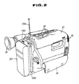
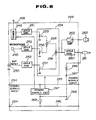
- Figs. 1 and 2 show a first embodiment of the present invention.
- a cabinet 10 include a mirror tube 11 formed along its lower left side. This mirror tube contains an optical lens or lenses which serve to focus an image on a CCD or the like type of transducer.
- a plurality of camera control ports 12 are formed along the side of the mirror tube 11.
- a view finder 13 is pivotally supported on the cabinet in the illustrated manner.
- a plurality of video control ports are formed along the upper edge of the cabinet via which the VTR which is included in the camera can be controlled.
- a microphone 15 is disposed at the forward end of the cabinet while a grip belt 16 is provided on the right hand side thereof. This belt 16 allows the camera to be held in the right hand.
- a battery mounting site 19 is provided along the rear edge of the cabinet 10. This mounting site permits a battery pack 20 be removably attached to the cabinet.
- the upper and lower edges of the mounting site 19 are formed with connection projections 21 which are respectively arranged to be slidably received in connection recesses 22 formed in upper and lower edges of the battery pack 20.
- a pack lock arrangement which is mounted in the cabinet 10, includes a slidable lock bolt 23 which can be moved via the manual operation of a release lever 24 which is disposed on the side of the cabinet 10 and which is operatively connected with the lock bolt 23.
- a pair of contact pins 25 are arranged to project rearwardly from the face of the mounting site a shown in Fig. 1. These pins are arranged to engage in corresponding pack sockets to establish an electrical connection between the battery pack and the circuitry included in the cabinet.
- a TV tuner adapter pack 128 is interposed between the battery pack 20 and the video camera cabinet 10.
- the front side of the TV tuner adapter pack 128 is provided with connection section 129 which is formed with connection recesses or slots 130 along the upper and lower edges in exactly the same manner as the battery pack 20.
- connection section 129 which is formed with connection recesses or slots 130 along the upper and lower edges in exactly the same manner as the battery pack 20.
- This arrangement allows the adapter pack to be connected to the mounting site 19 in exactly the same manner as the battery pack
- the rear side of the adapter pack 128 is provided with a mounting site 131 which is identical to the one provided on the rear edge of the video camera cabinet.
- the rear edge of the TV tuner adapter pack is formed with connection projections 132 along the upper and lower edges which projections are designed to engage in the recesses 22 formed in the uper and lower edges of the battery pack 20.
- mounting site 131 is also formed with contact pins 134 which are located in the same manner as those on the mounting site 19.
- a release bar 135 which is located on the side of the TV tuner adapter pack 128 is operatively connected with a lock bolt 133.
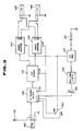
- Fig. 3 is a circuit diagram which shows the basic features of the circuitry of the TV tuner adapter pack 128.
- this diagram 138 denotes tuner block which is connected with a rod antenna 139 and an external antenna connection jack 140.
- the TV tuner block is connected with a VIF block 141 which is in turn connected with a video buffer 142 and an audio buffer 143.
- the latter two mentioned buffers 142 and 143 are respectively connected with A/V output jacks 145 and 146.
- the circuit further includes a voltage stabilizing circuit 147 and a direct current step up D/D converter 148.
- a tuning resistor 149 is circuited between the D/D converter and the tuner block 138 while a select switch 150 is circuited between the voltage stabilizing circuit 147 and the tuner block 138 and which is arranged to control the switching between VHF and UHF modes.
- the TV tuner pack 128 and the battery pack 20 are arranged in the manner schematically shown in Fig. 4.
- the connection projections 21 of the video camera are engaged in the connection slots 130 while the lock bolt 23 engages in a suitable recess formed in the front face of the TV tuner adapter pack 128.
- the guide projections and guide slots are laterally oriented and shaped such as to permit an adapter pack to be slid sideways in a manner which resembles a bayonet type connecting procedure, into an operative position, the provision of the lock bolts enable a simple and effective manner of locking the pack in question, in place.
- connection projections 132 are connected in the connection slots 22 of the battery pack 20, and the battery pack locked in place via projection of the lock bolt 133.
- the contact pins 25, 134 provide an eletric connection between the battery pack, the TV tuner adapter pack 128 and the video camera in a manner such that electrical power from the batteries contained in the battery pack can be supplied to both of the TV tuner adapter pack and the video camera which allows not only the video camera to be operated on the batteries but the TV tuner adapter pack as well.
- This of course eliminates the need for a separate power source for the TV tuner adapter pack and also eliminates the need to connect the video camera to a indoor type TV receiver.
- the broadcast which is received by the rod antenna 139 is supplied to the video camera in the form of a video or image signal and an audio or sound signal via the output jacks 145 and 146 shown in Fig. 3.
- the tuner block 138 is arranged to amplify the channel selected from the TV broadcast and to frequency convert the same about a center frequency of 58.75 MHz (video signal) or a center frequency of 54.25 MHz (audio signal).
- the VIF block 141 amplifies the middle frequency signal from the tuner block 138 and at the same time a demodulation circuit separates the image and audio signals. Following this, the image signal is supplied to the video buffer 142 while the audio signal is supplied to the audio buffer 143. These signals are respectively supplied via the A/V jacks 145 and 146 to the plug sockets formed in the video camera body. The thus supplied signals can then be recorded on the magnetic tape contained in a tape cassette loaded into the video camera as desired.
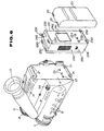
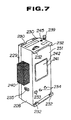
- Figs. 6 to 8 show a second embodiment of the invention.
- the TV tuner adapter pack 128 is replaced with a FM tuner pack.
- this FM tuner pack has essentially the same construction and arrangement as the adapter pack of the first embodiment.
- essentially the same set of numeral as used in connection with the first embodiment are used in connection with the instant one save that each has been incremented by 100.
- Newly identified elements are a selectively extendible microphone 240, a receiving section 241 and a cover 242 which covers the just mentioned section.
- Fig. 7 shows the microphone 240 in tis extended position.
- Fig. 8 shows an example of the circuitry which can be used in the FM tuner pack.
- 245 and 246 denote power supply lines which are operatively connected with the plus and minus terminals of the battery pack 20 via contact pins 234.
- Lines 245 and 246 are connected with a power supply circuit 247 via which the tunner circuit is supplied with electrical power.
- the microphone 240 and an external input jack 250 are arranged to supply input signals.
- Each of the tuner 248, the microphone 240, the external jack 250 are connected with level converter circuits 251, 252 and 253, respectively.
- the outputs of these three level converter circuits are supplied respectively to variable resistors 255, 256 and 257 which are included in an output mixing 254.
- the outputs of the variable resistors 255 and 256 are supplied to an adder 258 while the output fo the variable resistor 257 is supplied to an adder 259 along with the output of the adder 258.
- the output of the adder 259 is supplied by way of a level conversion circuit 260 to a microphone output pin 261.
- the output of the adder 259 is also supplied to an amplifier 262 which can be used to drive an earphone, headset or the like.
- the negative terminal of the microphone output pin 261 (which is used to supply a sound signal to the video camera) is connected via a coil 266 and a fixed resistor 267.
- This impedance circuit is connected with ground 268 and with a switch 269.
- This switch 269 provides a selective connection between the power source line 246 and the power supply circuit 247.
- both the camera and the FM tuner can be operated on the batteries contained in the battery pack 20. Viz., power from the battery pack 20 is supplied via the power supply lines 245, 256 to circuitry of the FM tuner and contact pins 25 of the camera.
- the rod antenna 238 picks up the broadcast waves and according to the predetermined frequency which the tuner is arranged to select, a signal is supplied via the level control circuit 251 and the variable resistor 255 to the adder 258. In the case narration is input via the microphone 240, this signal is also supplied to the adder 258 via the level control circuit 252 and variable resistor 256. The combined signal is then supplied to the microphone output plus 261 and from this plug to the video camera wherein it can be recorded on the sound track of the cassette tape.
- the FM tuner pack is provided with its own independent ground 268 which is connected to the minus terminal of the microphone output pin via an impedance circuit (#266, 267).
- an impedance circuit #266, 267
- Figs. 9 to 12 show a third embodiment of the present invention.
- the adapter pack takes the form of an illumination adapter pack.
- Numerals which are used in connection with this embodiment are essentially the same as those used in connection with the first and second embodiments except the numerals which pertain the elements of the third embodiment are expressed in the 300's. Viz., the light pack becomes 328 etc.
- 338 and 339 denote a hinge and hinge pin via which a light support arm 340 is pivotally supported on the upper edge of the pack 328;
- 342 is a connection which supports a lamp 343 at the free end of the arm 340;
- 344 denotes a switch which is disposed on the right hand side of the pack and via which the light can be controlled;
- 345 is a cable via which the light pack can be connected with a remote control jack on the video camera.
- the hinge and the connection 342 allow the lamp 343 to be set at a number of different angles as required for indoor illumination.
- Fig. 12 The circuitry of the instant embodiment is illustrated in Fig. 12.
- 346 denotes a remote control connector plug which can be inserted into a jack 350 in the video camera. Jack 350 is connected with the main circuitry 349 of the camera.
- a comparator 351 has its non-inverting terminal (-) connected with the plug 346.
- the inverting input of the comparator is connected with a voltage divider comprised of fixed resistors 352 and 353.
- the output of the comparator 351 is connected with the base of a transistor 354 which controls the illumination of the lamp 343.
- the battery and light adapter packs can be used independently as a hand held flashlight or torch.
- the support arm 340 can be folded flat against the the front face of the pack and the lamp 343 oriented at a suitable angle. Operation of the switch 344 controls the illumination of the lamp 343.
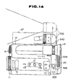
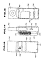
- Figs 13 and 14 show a fourth embodiment of the present invention.
- This embodiment is a variant of the third one and features the arrangement wherein the support arm 440 is fixedly mounted on the main body of the light adapter pack 428 and arranged to support a lamp 443 at the top thereof.
- the arm is arranged to be sufficiently long as to avoid interference with the cover 57 of the video camera which must be opened in order to permit cassette loading/unloading to be readily carried out.
- the lamp is arranged sufficiently high so as to avoid casting a shadow of the forward portion of the video camera when in use indoors.
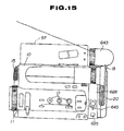
- Fig. 14 shows a further variant of the above type of light adapter pack wherein the support arm 540 is telescopic and the lamp 543 can be manually raised and lowered as desired.
- Fig. 15 shows a further design variant wherein the lamp 643 is set back on the body of the light adapter pack body so as to provide both a low profile and to avoid interference with the cover 57 via which cassettes are loaded and unloaded.
- Fig. 16 to 18 show another embodiment of the invention wherein the sides of the pack are provided with recesses 759 via which a lamp enclosure 743 can be raised and lowered.
- a pin 760 is provided to selectively release the enclosure 743 and allow the same to be raised to an operative position or slid down into a storage position.
- This embodiment like the preceding ones can be used independently as a hand held flashlight if so desired.
- the above embodiments of the invention are such as to obviate the need for an unsightly accessory shoe and multiple power sources while readily allowing one or more accessory packs to be snapped into place at the rear of the video camera and powered by a signal battery pack which is snapped on at one end of the "sandwich".
- the mounting sites on the camera and each of the packs enables power from the battery pack to be supplied through to the camera and to the pack(s) along the way.
- Inputs to the camera or controls from the camera to the packs is enable via suitable connector cables and plugs/jacks.
Landscapes
- Engineering & Computer Science (AREA)
- Multimedia (AREA)
- Signal Processing (AREA)
- Battery Mounting, Suspending (AREA)
Applications Claiming Priority (6)
| Application Number | Priority Date | Filing Date | Title |
|---|---|---|---|
| JP44943/90 | 1990-02-26 | ||
| JP44941/90 | 1990-02-26 | ||
| JP2044943A JP2940054B2 (ja) | 1990-02-26 | 1990-02-26 | ビデオカメラ |
| JP44942/90 | 1990-02-26 | ||
| JP2044941A JPH03247174A (ja) | 1990-02-26 | 1990-02-26 | ビデオカメラ |
| JP2044942A JPH03247175A (ja) | 1990-02-26 | 1990-02-26 | ビデオカメラ |
Publications (3)
| Publication Number | Publication Date |
|---|---|
| EP0444849A2 true EP0444849A2 (de) | 1991-09-04 |
| EP0444849A3 EP0444849A3 (en) | 1992-10-21 |
| EP0444849B1 EP0444849B1 (de) | 1996-12-04 |
Family
ID=27292070
Family Applications (1)
| Application Number | Title | Priority Date | Filing Date |
|---|---|---|---|
| EP91301494A Expired - Lifetime EP0444849B1 (de) | 1990-02-26 | 1991-02-25 | Videokamera mit wechselnden Zubehörteilen |
Country Status (3)
| Country | Link |
|---|---|
| US (1) | US5189520A (de) |
| EP (1) | EP0444849B1 (de) |
| DE (1) | DE69123378T2 (de) |
Cited By (6)
| Publication number | Priority date | Publication date | Assignee | Title |
|---|---|---|---|---|
| EP0520511A1 (de) * | 1991-06-28 | 1992-12-30 | Walter Hähnel | Batterie-Pack für eine Videokamera |
| EP0514284A3 (en) * | 1991-05-17 | 1993-07-21 | Sony Corporation | Lighting apparatus for video cameras and electrode device for its power supply |
| EP0682447A3 (de) * | 1994-05-12 | 1996-10-16 | Matsushita Electric Industrial Co Ltd | Videokamera. |
| US8687939B2 (en) | 2006-08-29 | 2014-04-01 | Sony Corporation | Recording/reproducing system, recording/reproducing apparatus, and method for controlling recording/reproducing apparatus |
| EP2787721A4 (de) * | 2011-11-29 | 2015-09-09 | Jvc Kenwood Corp | Bildaufnahmevorrichtung |
| EA035224B1 (ru) * | 2018-10-08 | 2020-05-18 | Общество с ограниченной ответственностью "ИРВЭЙ" | Система инфракрасного ночного видения |
Families Citing this family (51)
| Publication number | Priority date | Publication date | Assignee | Title |
|---|---|---|---|---|
| JPH03280788A (ja) * | 1990-03-29 | 1991-12-11 | Sony Corp | ビデオカメラ |
| USD346614S (en) | 1991-01-31 | 1994-05-03 | Sony Corporation | Video camera combined with a video tape recorder |
| US5264935A (en) * | 1991-06-18 | 1993-11-23 | Sony Corporation | System for wireless transmission and reception of a video signal and corresponding audio signal |
| USD343183S (en) | 1991-10-04 | 1994-01-11 | Gold Star Co. Ltd. | Camcorder |
| USD342538S (en) | 1991-11-05 | 1993-12-21 | Matsushita Electric Industrial Co., Ltd. | Video camera with video tape recorder |
| USD343403S (en) | 1991-12-26 | 1994-01-18 | Matsushita Electric Industrial Co., Ltd. | Video camera with video tape recorder |
| USD342540S (en) | 1991-12-26 | 1993-12-21 | Matsushita Electric Industrial Co., Ltd. | Video camera with video tape recorder |
| USD346615S (en) | 1992-01-31 | 1994-05-03 | Sony Corporation | Video camera combined with a video tape recorder |
| US5408380A (en) * | 1992-03-09 | 1995-04-18 | Milliken Research Corporation | Method and apparatus for load voltage compensation |
| WO1993021729A1 (en) * | 1992-04-09 | 1993-10-28 | Anton/Bauer, Inc. | Interface unit for coupling between a host device, an auxiliary device, and a power source |
| US5428254A (en) * | 1992-11-09 | 1995-06-27 | Duracell Inc. | Universal energy pack |
| USD356807S (en) | 1993-03-12 | 1995-03-28 | Hitachi, Ltd. | Combined video tape recorder and camera |
| US5568205A (en) * | 1993-07-26 | 1996-10-22 | Telex Communications, Inc. | Camera mounted wireless audio/video transmitter system |
| US5455625A (en) * | 1993-09-23 | 1995-10-03 | Rosco Inc. | Video camera unit, protective enclosure and power circuit for same, particularly for use in vehicles |
| USD356100S (en) | 1993-11-17 | 1995-03-07 | Matsushita Electric Industrial Co., Ltd. | Video camera with video tape recorder |
| USD356099S (en) | 1994-01-21 | 1995-03-07 | Matsushita Electric Industrial Co., Ltd. | Video camera with video tape recorder |
| JPH07264452A (ja) * | 1994-02-03 | 1995-10-13 | Samsung Electron Co Ltd | カメラ一体型の磁気記録再生装置およびその方法 |
| USD370491S (en) | 1994-09-14 | 1996-06-04 | Matsushita Electric Industrial Co., Ltd. | Video camera with video tape recorder |
| USD364633S (en) | 1994-09-29 | 1995-11-28 | Matsushita Electric Industrial Co., Ltd. | Video camera with video tape recorder |
| USD373778S (en) | 1995-04-07 | 1996-09-17 | Avid Technology, Inc. | Combined front panel display and associated input unit for a video camera |
| US6522761B1 (en) * | 1996-08-07 | 2003-02-18 | The United States Of America As Represented By The Secretary Of The Navy | Directionally sensitive pointing microphone |
| US6786420B1 (en) | 1997-07-15 | 2004-09-07 | Silverbrook Research Pty. Ltd. | Data distribution mechanism in the form of ink dots on cards |
| US6618117B2 (en) | 1997-07-12 | 2003-09-09 | Silverbrook Research Pty Ltd | Image sensing apparatus including a microcontroller |
| US6624848B1 (en) | 1997-07-15 | 2003-09-23 | Silverbrook Research Pty Ltd | Cascading image modification using multiple digital cameras incorporating image processing |
| US6879341B1 (en) | 1997-07-15 | 2005-04-12 | Silverbrook Research Pty Ltd | Digital camera system containing a VLIW vector processor |
| US6690419B1 (en) * | 1997-07-15 | 2004-02-10 | Silverbrook Research Pty Ltd | Utilising eye detection methods for image processing in a digital image camera |
| US20040119829A1 (en) | 1997-07-15 | 2004-06-24 | Silverbrook Research Pty Ltd | Printhead assembly for a print on demand digital camera system |
| US7110024B1 (en) | 1997-07-15 | 2006-09-19 | Silverbrook Research Pty Ltd | Digital camera system having motion deblurring means |
| USD408784S (en) | 1997-09-11 | 1999-04-27 | Sony Corporation | Adaptor for video camera |
| USD407687S (en) | 1998-01-30 | 1999-04-06 | Canon Kabushiki Kaisha | DC power supply |
| US6101339A (en) * | 1998-04-10 | 2000-08-08 | Minolta Co., Ltd. | Camera and system operating from a secondary battery |
| US6099141A (en) | 1998-07-06 | 2000-08-08 | Sony Corporation | Roadside emergency security flashlight |
| AUPP702098A0 (en) | 1998-11-09 | 1998-12-03 | Silverbrook Research Pty Ltd | Image creation method and apparatus (ART73) |
| AUPQ056099A0 (en) | 1999-05-25 | 1999-06-17 | Silverbrook Research Pty Ltd | A method and apparatus (pprint01) |
| JP3935291B2 (ja) * | 1999-06-25 | 2007-06-20 | シチズンホールディングス株式会社 | 電気機器用電源アダプタ収納体 |
| US7403232B1 (en) * | 2000-09-01 | 2008-07-22 | Eastman Kodak Company | Intelligent power management system |
| USD478608S1 (en) | 2002-08-22 | 2003-08-19 | Creo Il. Ltd. | Portable hard disc, communication and battery pack unit for a digital camera back |
| US20050036034A1 (en) * | 2003-08-15 | 2005-02-17 | Rea David D. | Apparatus for communicating over a network images captured by a digital camera |
| USD506493S1 (en) * | 2004-06-29 | 2005-06-21 | Olympus Corporation | Adapter for a digital camera |
| BRPI0708480A2 (pt) * | 2006-03-02 | 2011-05-31 | Athenix Corp | processos e composições para aperfeiçoada atividade de enzima em plantas transgênicas |
| GB0617399D0 (en) * | 2006-09-06 | 2006-10-11 | Hawk Woods Ltd | Battery system interface |
| US8525925B2 (en) | 2008-12-29 | 2013-09-03 | Red.Com, Inc. | Modular digital camera |
| US8525924B2 (en) * | 2008-12-29 | 2013-09-03 | Red.Com, Inc. | Modular motion camera |
| US9681028B2 (en) | 2013-03-15 | 2017-06-13 | Red.Com, Inc. | Digital camera with wireless connectivity |
| WO2015153787A1 (en) | 2014-04-04 | 2015-10-08 | Red.Com, Inc. | Broadcast module for a digital camera |
| US10194071B2 (en) | 2015-04-03 | 2019-01-29 | Red.Com, Llc | Modular motion camera |
| JP2018518080A (ja) | 2015-04-03 | 2018-07-05 | レッド.コム,エルエルシー | モジュール式モーションカメラ |
| US10116776B2 (en) | 2015-12-14 | 2018-10-30 | Red.Com, Llc | Modular digital camera and cellular phone |
| US10448157B2 (en) | 2017-01-20 | 2019-10-15 | Samson Technologies Corp. | Microphone receiver and microphone receiver system |
| US11451700B2 (en) | 2019-03-06 | 2022-09-20 | Aob Products Company | Game camera having camera control module |
| US11711603B1 (en) | 2022-02-10 | 2023-07-25 | Gopro, Inc. | Modular camera with interchangeable image head and sub-system bases |
Family Cites Families (10)
| Publication number | Priority date | Publication date | Assignee | Title |
|---|---|---|---|---|
| JPS57173272A (en) * | 1981-04-17 | 1982-10-25 | Canon Inc | Video camera system |
| GB2184897B (en) * | 1985-10-15 | 1989-10-18 | Pag Ltd | Battery connector |
| GB2183936A (en) * | 1985-12-06 | 1987-06-10 | Plessey Co Plc | Power supply adaptor |
| US4764817A (en) * | 1987-06-10 | 1988-08-16 | Leonard Bloom | Video recording camera |
| JPH01126659U (de) * | 1988-02-10 | 1989-08-30 | ||
| US4969046A (en) * | 1988-06-03 | 1990-11-06 | Sony Corporation | Television monitor system |
| US4924246A (en) * | 1988-09-29 | 1990-05-08 | Asahi Research Corporation | Energizing system for video cameras and lights using adapter modules |
| GB8924308D0 (en) * | 1989-10-28 | 1989-12-13 | Wiltshire Roger L | Wireless monitoring of vision & sound associated with mobile television cameras/recorders |
| JPH0543572Y2 (de) * | 1990-03-16 | 1993-11-02 | ||
| JPH03280030A (ja) * | 1990-03-29 | 1991-12-11 | Sony Corp | ビデオカメラのキャリングハンドル |
-
1991
- 1991-02-25 EP EP91301494A patent/EP0444849B1/de not_active Expired - Lifetime
- 1991-02-25 DE DE69123378T patent/DE69123378T2/de not_active Expired - Fee Related
- 1991-02-25 US US07/660,786 patent/US5189520A/en not_active Expired - Lifetime
Cited By (9)
| Publication number | Priority date | Publication date | Assignee | Title |
|---|---|---|---|---|
| EP0514284A3 (en) * | 1991-05-17 | 1993-07-21 | Sony Corporation | Lighting apparatus for video cameras and electrode device for its power supply |
| US5588732A (en) * | 1991-05-17 | 1996-12-31 | Sony Corporation | Video lighting apparatus and electrode apparatus therefor |
| EP0520511A1 (de) * | 1991-06-28 | 1992-12-30 | Walter Hähnel | Batterie-Pack für eine Videokamera |
| EP0682447A3 (de) * | 1994-05-12 | 1996-10-16 | Matsushita Electric Industrial Co Ltd | Videokamera. |
| US5742341A (en) * | 1994-05-12 | 1998-04-21 | Matsushita Electric Industrial Co., Ltd. | Video camera having a plurality of housings for a variety of operations |
| US8687939B2 (en) | 2006-08-29 | 2014-04-01 | Sony Corporation | Recording/reproducing system, recording/reproducing apparatus, and method for controlling recording/reproducing apparatus |
| EP2787721A4 (de) * | 2011-11-29 | 2015-09-09 | Jvc Kenwood Corp | Bildaufnahmevorrichtung |
| US9319572B2 (en) | 2011-11-29 | 2016-04-19 | JVC Kenwood Corporation | Image pickup device |
| EA035224B1 (ru) * | 2018-10-08 | 2020-05-18 | Общество с ограниченной ответственностью "ИРВЭЙ" | Система инфракрасного ночного видения |
Also Published As
| Publication number | Publication date |
|---|---|
| EP0444849B1 (de) | 1996-12-04 |
| US5189520A (en) | 1993-02-23 |
| DE69123378D1 (de) | 1997-01-16 |
| DE69123378T2 (de) | 1997-04-10 |
| EP0444849A3 (en) | 1992-10-21 |
Similar Documents
| Publication | Publication Date | Title |
|---|---|---|
| US5189520A (en) | Video camera modular accessory apparatus | |
| US5264935A (en) | System for wireless transmission and reception of a video signal and corresponding audio signal | |
| US5696555A (en) | Image input apparatus having a detachably connected camera body and monitor or control unit | |
| US5341171A (en) | Video camera apparatus with a connecting device for easy connection with electric apparatus | |
| EP0355217A1 (de) | Tragbare Videokamera mit eingebauter Audioquelle mit synchronisiertem Wiederstart | |
| JPH08275098A (ja) | ビデオカメラ | |
| US4539601A (en) | Portable video system | |
| JP3518016B2 (ja) | ビデオカメラ装置 | |
| US5226708A (en) | Lighting device for use with video camera | |
| JP2713314B2 (ja) | バッテリカプラ | |
| JP3089703B2 (ja) | ビデオカメラのバッテリー充電装置 | |
| US5394063A (en) | Video light apparatus | |
| JP2585813B2 (ja) | ビデオカメラのアクセサリー | |
| JPS59122188A (ja) | ビデオ入力端子回路 | |
| JPH03247175A (ja) | ビデオカメラ | |
| JP3143255B2 (ja) | 携帯vtrとその接続ステーション | |
| JPH03247174A (ja) | ビデオカメラ | |
| JP2601935B2 (ja) | リモコン装置 | |
| JPH06284320A (ja) | ビデオ一体形カメラ | |
| JPH03276974A (ja) | ビデオカメラ | |
| JP4602587B2 (ja) | テレビカメラの操作ユニット装置 | |
| JP2940054B2 (ja) | ビデオカメラ | |
| JPH0548942A (ja) | ビデオワイヤレス送信機 | |
| JPS6329341Y2 (de) | ||
| JP4129159B2 (ja) | カメラ用アクセサリ |
Legal Events
| Date | Code | Title | Description |
|---|---|---|---|
| PUAI | Public reference made under article 153(3) epc to a published international application that has entered the european phase |
Free format text: ORIGINAL CODE: 0009012 |
|
| AK | Designated contracting states |
Kind code of ref document: A2 Designated state(s): DE FR GB NL |
|
| PUAL | Search report despatched |
Free format text: ORIGINAL CODE: 0009013 |
|
| AK | Designated contracting states |
Kind code of ref document: A3 Designated state(s): DE FR GB NL |
|
| 17P | Request for examination filed |
Effective date: 19930320 |
|
| 17Q | First examination report despatched |
Effective date: 19950315 |
|
| GRAG | Despatch of communication of intention to grant |
Free format text: ORIGINAL CODE: EPIDOS AGRA |
|
| GRAH | Despatch of communication of intention to grant a patent |
Free format text: ORIGINAL CODE: EPIDOS IGRA |
|
| GRAH | Despatch of communication of intention to grant a patent |
Free format text: ORIGINAL CODE: EPIDOS IGRA |
|
| GRAA | (expected) grant |
Free format text: ORIGINAL CODE: 0009210 |
|
| AK | Designated contracting states |
Kind code of ref document: B1 Designated state(s): DE FR GB NL |
|
| REF | Corresponds to: |
Ref document number: 69123378 Country of ref document: DE Date of ref document: 19970116 |
|
| ET | Fr: translation filed | ||
| PLBE | No opposition filed within time limit |
Free format text: ORIGINAL CODE: 0009261 |
|
| STAA | Information on the status of an ep patent application or granted ep patent |
Free format text: STATUS: NO OPPOSITION FILED WITHIN TIME LIMIT |
|
| 26N | No opposition filed | ||
| REG | Reference to a national code |
Ref country code: GB Ref legal event code: IF02 |
|
| PGFP | Annual fee paid to national office [announced via postgrant information from national office to epo] |
Ref country code: FR Payment date: 20020212 Year of fee payment: 12 |
|
| PGFP | Annual fee paid to national office [announced via postgrant information from national office to epo] |
Ref country code: GB Payment date: 20020227 Year of fee payment: 12 |
|
| PGFP | Annual fee paid to national office [announced via postgrant information from national office to epo] |
Ref country code: NL Payment date: 20020228 Year of fee payment: 12 |
|
| PGFP | Annual fee paid to national office [announced via postgrant information from national office to epo] |
Ref country code: DE Payment date: 20020314 Year of fee payment: 12 |
|
| PG25 | Lapsed in a contracting state [announced via postgrant information from national office to epo] |
Ref country code: GB Free format text: LAPSE BECAUSE OF NON-PAYMENT OF DUE FEES Effective date: 20030225 |
|
| PG25 | Lapsed in a contracting state [announced via postgrant information from national office to epo] |
Ref country code: NL Free format text: LAPSE BECAUSE OF NON-PAYMENT OF DUE FEES Effective date: 20030901 |
|
| PG25 | Lapsed in a contracting state [announced via postgrant information from national office to epo] |
Ref country code: DE Free format text: LAPSE BECAUSE OF NON-PAYMENT OF DUE FEES Effective date: 20030902 |
|
| GBPC | Gb: european patent ceased through non-payment of renewal fee | ||
| PG25 | Lapsed in a contracting state [announced via postgrant information from national office to epo] |
Ref country code: FR Free format text: LAPSE BECAUSE OF NON-PAYMENT OF DUE FEES Effective date: 20031031 |
|
| NLV4 | Nl: lapsed or anulled due to non-payment of the annual fee |
Effective date: 20030901 |
|
| REG | Reference to a national code |
Ref country code: FR Ref legal event code: ST |