EP0443469A2 - Rotorfilterpresse mit geteilten Filterplatten - Google Patents
Rotorfilterpresse mit geteilten Filterplatten Download PDFInfo
- Publication number
- EP0443469A2 EP0443469A2 EP91102219A EP91102219A EP0443469A2 EP 0443469 A2 EP0443469 A2 EP 0443469A2 EP 91102219 A EP91102219 A EP 91102219A EP 91102219 A EP91102219 A EP 91102219A EP 0443469 A2 EP0443469 A2 EP 0443469A2
- Authority
- EP
- European Patent Office
- Prior art keywords
- filter plate
- sector
- shaft
- filter
- rotor
- Prior art date
- Legal status (The legal status is an assumption and is not a legal conclusion. Google has not performed a legal analysis and makes no representation as to the accuracy of the status listed.)
- Granted
Links
- 238000009434 installation Methods 0.000 abstract description 4
- 239000007788 liquid Substances 0.000 description 3
- 238000003780 insertion Methods 0.000 description 2
- 230000037431 insertion Effects 0.000 description 2
- 230000002411 adverse Effects 0.000 description 1
- 230000000694 effects Effects 0.000 description 1
- 239000004744 fabric Substances 0.000 description 1
- 239000000706 filtrate Substances 0.000 description 1
- 239000000463 material Substances 0.000 description 1
- 125000006850 spacer group Chemical group 0.000 description 1
Images
Classifications
-
- B—PERFORMING OPERATIONS; TRANSPORTING
- B01—PHYSICAL OR CHEMICAL PROCESSES OR APPARATUS IN GENERAL
- B01D—SEPARATION
- B01D29/00—Filters with filtering elements stationary during filtration, e.g. pressure or suction filters, not covered by groups B01D24/00 - B01D27/00; Filtering elements therefor
- B01D29/39—Filters with filtering elements stationary during filtration, e.g. pressure or suction filters, not covered by groups B01D24/00 - B01D27/00; Filtering elements therefor with hollow discs side by side on, or around, one or more tubes, e.g. of the leaf type
-
- B—PERFORMING OPERATIONS; TRANSPORTING
- B01—PHYSICAL OR CHEMICAL PROCESSES OR APPARATUS IN GENERAL
- B01D—SEPARATION
- B01D29/00—Filters with filtering elements stationary during filtration, e.g. pressure or suction filters, not covered by groups B01D24/00 - B01D27/00; Filtering elements therefor
- B01D29/76—Handling the filter cake in the filter for purposes other than for regenerating
- B01D29/86—Retarding cake deposition on the filter during the filtration period, e.g. using stirrers
-
- B—PERFORMING OPERATIONS; TRANSPORTING
- B01—PHYSICAL OR CHEMICAL PROCESSES OR APPARATUS IN GENERAL
- B01D—SEPARATION
- B01D29/00—Filters with filtering elements stationary during filtration, e.g. pressure or suction filters, not covered by groups B01D24/00 - B01D27/00; Filtering elements therefor
- B01D29/96—Filters with filtering elements stationary during filtration, e.g. pressure or suction filters, not covered by groups B01D24/00 - B01D27/00; Filtering elements therefor in which the filtering elements are moved between filtering operations; Particular measures for removing or replacing the filtering elements; Transport systems for filters
-
- B—PERFORMING OPERATIONS; TRANSPORTING
- B01—PHYSICAL OR CHEMICAL PROCESSES OR APPARATUS IN GENERAL
- B01D—SEPARATION
- B01D2201/00—Details relating to filtering apparatus
- B01D2201/28—Position of the filtering element
- B01D2201/282—Filtering elements with a horizontal rotation or symmetry axis
Definitions
- the invention relates to a rotor filter press, in which filter plates are arranged vertically on a support and are penetrated centrally by a horizontal shaft, in which each filter plate is provided with a filter on one side surface, forms a collecting space behind the filter and has an outlet opening at the bottom a collecting pipe runs under the filter plates, which is connected to the outlet opening of the associated filter plate via a connecting piece, and in which each filter plate is divided into filter plate sectors, and a lower filter plate sector has the outlet opening, via an intermediate piece from the shaft at a distance is separated and is pushed by means of a rotary movement around the shaft between the shaft and the carrier / the collecting tube.
- each manifold connection piece is a connecting hose which is attached to the outlet opening by means of a flange.
- the intermediate piece is a plain bearing ring that sits firmly on the shaft and continuously fills the distance between the shaft and the filter plate sector. It is difficult and cumbersome to mount the connections of the filter plates hindered by the collector tube and the support under the filter plates. It is also cumbersome to insert the lower filter plate sectors with the correct fit. When using the rotor filter press, the filter plates must often be removed, cleaned and reinserted.
- each manifold connection piece is a connecting piece over which the associated lower filter plate sector with the outlet opening is pushed along a lowering section, that the lowering section is adapted to the distance between the lower filter plate sector and the shaft and that the intermediate piece is designed as a ring segment which is pushed by means of a rotary movement around the shaft between the shaft and the lower filter plate sector.
- the space provided for the ring segment intermediate piece is initially available as free space, so that the filter plate sector can be pushed under the shaft in a simplified manner.
- the lower filter plate sector is connected to the collecting space by lowering onto the connecting piece. Then the intermediate ring segment is inserted into the shaft and the assembly of the lower filter plate sector is finished.
- the ring segment is a compensating part and has essentially no support function for the shaft, since the shaft is essentially not supported on the filter plates.
- the two sides of the filter plate need not be separated from one another in a liquid-tight manner, so that the joint between the ring segment and the lower filter plate sector and the shaft need not be tight.
- the free space provided for the installation and removal of the lower filter plate sector is filled by the ring segment, since the free space would adversely affect the flow conditions on the side of the filter plate provided with the filter. Currents with a cross-flow effect are generated on this side by means of a rotor carried by the shaft, which are important for the filter to work effectively. Should the shaft press down a little under heavy load, it is supported by the ring segment intermediate piece, for which purpose this can be designed as a bearing, for example as a sliding part.
- a fixing device which fixes the ring segment on the lower filter plate sector and which e.g. is a screw connection. It is particularly expedient and advantageous if the lower filter plate sector and the intermediate ring segment engage with one another by means of a tongue and groove device.
- the tongue and groove device guides the ring segment during insertion and anchors it against axial forces on the lower filter plate sector.
- the tongue and groove device also ensures sufficient tightness between the ring segment and the filter plate sector if it extends over the entire length of the joint of these two parts.
- the lower filter plate sector used is e.g. screwed to the carrier.
- the lower filter plate sector and the carrier engage with one another with a tongue and groove device.
- the tongue and groove engagement occurs when the lower filter plate sector is lowered and holds the sector sufficiently.
- the filter plate sector is not screwed in against the friction of the tongue and groove engagement, but is screwed in without friction and then lowered radially.
- the tongue and groove device serves to axially fix the lower filter plate sector.
- the invention also consists in a rotor filter press, which is characterized in that a lower filter plate sector and a further filter plate sector abut one another with end faces and are held together in the plane of the plate by means of a holding device and in that a spacer is provided as a holding device which extends in the plate plane in the two filter plate sectors from the outer edge of the filter plate arranged screw presses the end faces of the filter plate sectors against each other.
- This "screwing" invention can also be used and claimed independently of the "ring segment” invention.
- the screwing of the sectors is simple in assembly, extends the outer contour of the filter plate not and guarantees stability and resistance to tipping against axial loads.
- the lower filter plate sector and a further filter plate sector lie against one another with end faces and are held together in the plate plane by means of a holding device. It is also appropriate to provide a fixing device acting between the intermediate ring segment and the lower filter plate sector. This fixing device should not be encrusted with deposits, since this disrupts the dismantling of the intermediate ring segment. The filter material should therefore be prevented from entering the fixing device.
- a particularly expedient and advantageous embodiment of the invention is characterized in that one end of the intermediate piece ring segment and one opening of a fixing device acting between the ring segment and the lower filter plate sector are aligned with the end face of the lower filter plate sector and the end face of the further filter plate sector extends over the ring segment End and the fixing device opening extends and that a provided as a holding device, which extends in the plate plane in the filter plate sectors and is arranged at a distance from the outer filter plate edge, presses the end face of the further filter plate sector against the ring segment end and seals over the fixing device opening.
- the screwing closer to the shaft holds the two filter plate sectors exactly in the plate plane, prevents canting from the plate plane and prevents the end face of the further filter plate sector from gaping relative to the ring segment end and the fixing device opening.
- the nut thread of the screw connection in the lower filter plate sector is arranged and a screw is inserted through channels in the two filter plate sectors.
- This design of the screw connection does not hinder the installation or removal of the lower filter plate sector.
- the screw connection simplifies the connection of the two filter plate sectors.
- the tongue attached to the carrier also engages in a groove in a further filter plate sector which connects to the further filter plate sector. This improves the rigidity and kink resistance of the connection of the filter plate sectors located in a common plane.
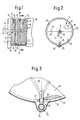
- the rotor filter press has two supports 1, only one of which is shown and which each carry a circular end plate 2, in which a shaft 3 is rotatably mounted, which can be driven by means of a motor 4 which is attached to the one support 1 .
- the shaft 3 carries circular rotor disks 5 arranged at a distance from one another, each of which is provided with elongated blades 6 on one side.
- a filter plate 7, which is penetrated centrally by the shaft 3, is arranged opposite the side provided with the wings 6.
- the filter plate 7 comprises a base plate 8, which is assigned to the wings carries a filter 9, which is designed as a filter cloth.
- a rotor disk 5 and a filter plate 7 define between them a chamber 10, 11, 12, three of which are shown and to which a liquid to be filtered is supplied via a line (not shown).
- a carrier 13 Between the two end plates 2 extends at the bottom a carrier 13, which is formed like a groove and in which the filter plates 7 are located.
- the channel-like carrier 13 forms a bulge 14 in the center below, in which a collecting tube 15 is arranged, which is connected to each filter plate 7 via a connecting piece 16 and an outlet opening 17.
- the line for the supply of the liquid to be filtered is also arranged in the bulge 14.
- a cylinder jacket 18 can be pushed in the axial direction over the chambers 10, 11, 12, so that the end plates 2 and the cylinder jacket 18 result in a sealed housing.
- the chambers do not need to be sealed against one another. From the liquid to be filtered, filtrate passes through the filters 9 into the base plates and flows off via the collecting pipe 15.
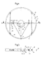
- each filter plate 7 is divided into two filter plate sectors 19, 20, the separating lines running outward from the shaft 3.
- the two dividing lines run horizontally.
- mouths 23 of the cavity or collecting space of the upper filter plate sector 20, not shown are sealingly pressed onto upper ends of drain channels 24, which are connected to the cavity or collecting space of the lower filter plate sector 19, which is not shown, and which to Guide outlet opening 17, in which the connecting piece 16 is inserted.
- the lower filter plate sector 19 faces the shaft 3 with a sector-shaped recess and is at a distance 25 from the shaft 3. The distance 25 is bridged by an intermediate ring segment 26 which is pushed into the recess.
- a continuous groove 27 is provided along the arcuate end face, into which a continuous spring 28 of the ring segment 26 engages.
- the groove 27 and the tongue 28 delimit a gap-like opening 29 which is covered by the end face 21 of the upper filter plate sector 20.
- a longitudinal groove 30 is provided on the end face thereof, which extends on both sides a little to the outer end face of the upper filter plate sector 20. Subsequent to each upper end of the groove 30, a short groove 35 is provided in the upper filter plate sector 20, into which the correspondingly long tongue 31 engages. Arch-like ledge-like springs 31 are provided on the carrier 13 and slide into the grooves 30 when the lower filter plate sector 19 is lowered.
- channels 32 which merge into one another and which do not cross the discharge channels 24 and are arranged next to them.
- a nut with a nut thread 33 is fixed in the channel 32, into which a long screw 34 is screwed, the head of which is supported near the upper edge of the upper filter plate sector 20.
- Two such screw connections 33, 34 are provided for connecting the two sectors 19, 20.
Landscapes
- Chemical & Material Sciences (AREA)
- Chemical Kinetics & Catalysis (AREA)
- Filtration Of Liquid (AREA)
- Centrifugal Separators (AREA)
- Filtering Of Dispersed Particles In Gases (AREA)
Abstract
Description
- Die Erfindung betrifft eine Rotorfilterpresse, bei der Filterplatten vertikal angeordnet auf einem Träger stehen und von einer horizontalen Welle mittig durchdrungen sind, bei der jede Filterplatte an einer Seitenfläche mit einem Filter versehen ist, hinter dem Filter einen Sammelraum bildet und unten eine Auslaßöffnung aufweist, bei der unter den Filterplatten ein Sammelrohr verläuft, das jeweils über ein Anschlußstück mit der Auslaßöffnung der zugeordneten Filterplatte montierbar verbunden ist, und bei der jede Filterplatte in Filterplattensektoren geteilt ist, und ein unterer Filterplattensektor die Auslaßöffnung aufweist, über ein Zwischenstück von der Welle mit einem Abstand getrennt ist und mittels einer Drehbewegung um die Welle zwischen die Welle und den Träger/das Sammelrohr geschoben ist.
- Bei einer bekannten (EP-OS 0 324 865) Rotorfilterpresse dieser Art ist jedes Sammelrohr-Anschlußstück ein Anschlußschlauch, der an die Auslaßöffnung mittels Flansch anmontiert wird. Das Zwischenstück ist ein Gleitlagerring, der fest auf der Welle sitzt und den Abstand zwischen Welle und Filterplattensektor dauernd ausfüllt. Es ist schwierig und umständlich, die Anschlüsse der Filterplatten behindert durch das Sammelrohr und den Träger unter den Filterplatten zu montieren. Auch ist das passend genau eingefügte Einschieben der unteren Filterplattensektoren umständlich. Bei Benutzung der Rotorfilterpresse sind die Filterplatten häufig herauszunehmen, zu reinigen und wieder einzusetzen.
- Eine Aufgabe der Erfindung ist es daher, eine Rotorfilterpresse der eingangs genannten Art zu schaffen, bei welcher der Ein- und Ausbau der unteren Filterplattensektoren hinsichtlich des Einschiebens und des Anschließens vereinfacht ist. Die erfindungsgemäße Rotorfilterpresse ist, diese Aufgabe losend, dadurch gekennzeichnet, daß jedes Sammelrohr-Anschlußstück ein Anschlußstutzen ist, über den der zugehörige untere Filterplattensektor mit der Auslaßöffnung entlang einer Absenkstrecke geschoben ist, daß die Absenkstrecke dem Abstand zwischen dem unteren Filterplattensektor und der Welle angepaßt ist und daß das Zwischenstück als Ringsegment ausgebildet ist, das mittels einer Drehbewegung um die Welle zwischen die Welle und den unteren Filterplattensektor geschoben ist.
- Beim Einbau des unteren Filterplattensektors ist der für das Ringsegment-Zwischenstück vorgesehene Raum zunächst als Freiraum vorhanden, so daß der Filterplattensektor vereinfacht unter die Welle schiebbar ist. Die Verbindung des unteren Filterplattensektors mit dem Sammelraum erfolgt durch Absenken auf den Anschlußstutzen. Sodann wird bei der Welle das Zwischenstück-Ringsegment eingeschoben und die Montage des unteren Filterplattensektors ist beendet.
- Das Ringsegment ist ein Ausgleichsteil und hat im wesentlichen keine Stützfunktion für die Welle, da die Welle an den Filterplatten im wesentlichen nicht gelagert ist. Die beiden Seiten der Filterplatte brauchen nicht flüssigkeitsdicht voneinander getrennt zu sein, so daß der Stoß zwischen dem Ringsegment und dem unteren Filterplattensektor und der Welle nicht dicht zu sein braucht. Der für den Ein- bzw. Ausbau des unteren Filterplattensektors vorgesehene Freiraum wird durch das Ringsegment ausgefüllt, da der Freiraum die Strömungsverhältnisse auf der mit dem Filter versehenen Seite der Filterplatte nachteilig beeinflussen würde. Auf dieser Seite werden mittels eines von der Welle getragenen Rotors Strömungen mit Cross-Flow-Effekt erzeugt, die für ein günstiges Wirken des Filters wichtig sind. Sollte die Welle bei starker Belastung etwas nach unten drücken, so wird sie von dem Ringsegment-Zwischenstück lagernd abgestützt, wozu dieses als Lager, z.B. als Gleitteil, ausgebildet sein kann.
- Es ist in der Regel eine Festlegeeinrichtung vorgesehen, welche das Ringsegment an dem unteren Filterplattensektor festlegt und die z.B. eine Verschraubung ist. Besonders zweckmäßig und vorteilhaft ist es, wenn der untere Filterplattensektor und das Zwischenstück-Ringsegment mit einer Nut-Feder-Einrichtung ineinandergreifen. Die Nut-Feder-Einrichtung führt das Ringsegment beim Einschieben und verankert es gegen axiale Kräfte an dem unteren Filterplattensektor. Die Nut-Feder-Einrichtung bewirkt auch eine ausreichende Dichtheit zwischen Ringsegment und Filterplattensektor, wenn sie sich über die gesamte Länge des Stoßes dieser beiden Teile erstreckt.
- Der eingesetzte untere Filterplattensektor ist z.B. an den Träger angeschraubt. Besonders zweckmäßig und vorteilhaft ist es jedoch, wenn der untere Filterplattensektor und der Träger mit einer Nut-Feder-Einrichtung ineinandergreifen. Der Nut-Feder-Eingriff entsteht beim Absenken des unteren Filterplattensektors und hält den Sektor ausreichend fest. Der Filterplattensektor wird nicht gegen die Reibung des Nut-Feder-Eingriffes eingedreht, sondern reibungsfrei eingedreht und dann radial abgesenkt. Die Nut-Feder-Einrichtung dient der axialen Fixierung des unteren Filterplattensektors.
- Die Erfindung besteht auch in einer Rotorfilterpresse, die dadurch gekennzeichnet ist, daß ein unterer Filterplattensektor und ein weiterer Filterplattensektor mit Stirnseiten aneinanderliegen und mittels einer Zusammenhalteeinrichtung in Plattenebene zusammengehalten sind und daß eine als Zusammenhalteeinrichtung vorgesehene, sich in Plattenebene in den beiden Filterplattensektoren erstreckende, mit Abstand vom äußeren Filterplattenrand angeordnete Verschraubung die Stirnseiten der Filterplattensektoren gegeneinander preßt. Diese "Verschraubung"-Erfindung ist auch unabhängig von der "Ringsegment"-Erfindung brauchbar und beansprucht. Die Verschraubung der Sektoren ist in der Montage einfach, erweitert die Außenkontur der Filterplatte nicht und gewährleistet Stabilität sowie Kippfestigkeit gegen axiale Belastungen.
- In der Regel ist bei der hier zur Rede stehenden Rotorfilterpresse vorgesehen, daß der untere Filterplattensektor und ein weiterer Filterplattensektor mit Stirnseiten aneinanderliegen und mittels einer Zusammenhalteeinrichtung in Plattenebene zusammengehalten sind. Es ist auch angebracht, eine zwischen dem Zwischenstück-Ringsegment und dem unteren Filterplattensektor wirkende Festlegeeinrichtung vorzusehen. Dieser Festlegeeinrichtung sollte durch Ablagerungen nicht verkrustet, da dies die Demontage des Zwischenstück-Ringsegmentes stört. Ein Zutritt des Filtergutes zu der Festlegeeinrichtung sollte also verhindert sein.
- Eine besonders zweckmäßige und vorteilhafte Ausführungsform der Erfindung ist dadurch gekennzeichnet, daß eine Ende des Zwischenstück-Ringsegmentes und eine Öffnung einer zwischen dem Ringsegment und dem unteren Filterplattensektor wirkenden Festlegeeinrichtung mit der Stirnseite des unteren Filterplattensektors fluchten und die Stirnseite des weiteren Filterplattensektors sich über das Ringsegment-Ende und die Festlegeeinrichtung-Öffnung erstreckt und daß eine als Zusammenhalteeinrichtung vorgesehene, sich in Plattenebene in den bei den Filterplattensektoren erstreckende, mit Abstand vom äußeren Filterplattenrand angeordnete Verschraubung die Stirnseite des weiteren Filterplattensektors gegen das Ringsegment-Ende und dichtend über die Festlegeeinrichtung-Öffnung preßt. Die der Welle näher gerückte Verschraubung hält die beiden Filterplattensektoren genau in der Plattenebene, verhindert Verkantungen aus der Plattenebene und ein Klaffen der Stirnseite des weiteren Filterplattensektors relativ zum Ringsegment-Ende und zur Festlegeeinrichtung-Öffnung.
- Besonders zweckmäßig und vorteilhaft ist es dabei, wenn das Mutterngewinde der Verschraubung im unteren Filterplattensektor angeordnet ist und eine Schraube durch Kanäle in den beiden Filterplattensektoren gesteckt ist. Diese Gestaltung der Verschraubung behindert den Ein- bzw. Ausbau des unteren Filterplattensektors nicht. Die Verschraubung vereinfacht die Verbindung der beiden Filterplattensektoren miteinander.
- Besonders zweckmäßig und vorteilhaft ist es, wenn die am Träger angebrachte Feder auch in eine Nut eines weiteren Filterplattensektors greift, der an den weiteren Filterplattensektor anschließt. Dies verbessert die Steifigkeit und Knickfestigkeit der Verbindung der in einer gemeinsamen Ebene befindlichen Filterplattensektoren.
- In der Zeichnung ist eine bevorzugte Ausführungsform der Erfindung dargestellt und zeigt
- Fig. 1
- eine Seitenansicht eines Teiles einer Rotorfilterpresse mit geteilten Filterplatten,
- Fig. 2
- einen Schnitt gemäß Linie II-II in Fig. 1,
- Fig. 3
- einen Ausschnitt der Darstellung in Fig. 2 in einem gegenüber Fig. 2 vergrößerten Maßstab,
- Fig. 4
- eine Filterplatte der Rotorfilterpresse gemäß Fig. 1 in einem gegenüber Fig. 1 vergrößerten Maßstab und
- Fig. 5
- eine Ansicht gemäß Linie V-V in Fig. 1.
- Die Rotorfilterpresse gemäß Zeichnung weist zwei Stützen 1 auf, von denen nur eine gezeigt ist und die jeweils eine kreisrunde Endplatte 2 tragen, in denen eine Welle 3 drehbar gelagert ist, die mittels eines Motors 4 antreibbar ist, der an der einen Stütze 1 befestigt ist. Die Welle 3 trägt mit Abstand voneinander angeordnete kreisunde Rotorscheiben 5, die jeweils auf einer Seite mit länglichen Flügeln 6 besetzt sind. Der mit den Flügeln 6 versehenen Seite gegenüber ist jeweils eine Filterplatte 7 angeordnet, die von der Welle 3 mittig durchdrungen ist. Die Filterplatte 7 umfaßt eine Grundplatte 8, die den Flügeln zugeordnet einen Filter 9 trägt, der als Filtertuch ausgebildet ist. Jeweils eine Rotorscheibe 5 und eine Filterplatte 7 begrenzen zwischen sich eine Kammer 10, 11, 12 von denen drei gezeigt sind und denen über eine nicht gezeigte Leitung eine zu filternde Flüssigkeit zugeführt wird. Zwischen den beiden Endplatten 2 erstreckt sich unten ein Träger 13, der rinnenartig ausgebildet ist und in dem die Filterplatten 7 stehen. Der rinnenartige Träger 13 bildet mittig unten eine Ausbauchung 14, in der ein Sammelrohr 15 angeordnet ist, das mit jeder Filterplatte 7 über einen Anschlußstutzen 16 und eine Auslaßöffnung 17 verbunden ist. Die Leitung für die Zufuhr der zu filternden Flüssigkeit wird ebenfalls in der Ausbauchung 14 angeordnet. Ein Zylindermantel 18 läßt sich in axialer Richtung über die Kammern 10, 11, 12 schieben, so daß die Endplatten 2 und der Zylindermantel 18 ein dichtes Gehäuse ergeben. Die Kammern brauchen gegeneinander nicht dicht zu sein. Von der zu filternden Flüssigkeit gelangt durch die Filter 9 in die Grundplatten Filtrat, das über das Sammelrohr 15 abfließt.
- Wie aus Fig. 3-5 deutlicher hervorgeht, ist jede Filterplatte 7 in zwei Filterplattensektoren 19, 20 unterteilt, wobei die Trennlinien von der Welle 3 nach außen verlaufen. Im vorliegenden Fall verlaufen die beiden Trennlinien waagerecht. An den aneinanderliegenden Stirnseiten 21, 22 sind Mündungen 23 des nicht gezeigten Hohlraumes bzw. Sammelraumes des oberen Filterplattensektors 20 an obere Enden von Ablaufkanälen 24 dichtend gepreßt, die mit dem nicht gezeigten Hohlraum bzw. Sammelraum des unteren Filterplattensektors 19 in Verbindung stehen und die zu der Auslaßöffnung 17 führen, in welcher der Anschlußstutzen 16 steckt. Der untere Filterplattensektor 19 wendet der Welle 3 eine sektorförmige Ausnehmung zu und hat von der Welle 3 einen Abstand 25. Der Abstand 25 ist von einem Zwischenstück-Ringsegment 26 überbrückt, das in die Ausnehmung geschoben ist. Im Bereich der Ausnehmung ist entlang der bogenförmigen Stirnseite eine durchgehende Nut 27 vorgesehen, in welche eine durchgehende Feder 28 des Ringsegmentes 26 greift. Zur Stirnseite 22 des unteren Filterplattensektors 19 hin begrenzen die Nut 27 und die Feder 28 eine spaltartige Öffnung 29, die von der Stirnseite 21 des oberen Filterplattensektors 20 überdeckt ist.
- Entlang dem bogenförmigen Außenrand des unteren Filterplattensektors 19 ist an dessen Stirnseite eine längsverlaufende Nut 30 vorgesehen, die sich beiderseits auch ein wenig auf die äußere Stirnseite des oberen Filterplattensektors 20 erstreckt. Anschließend an jedes obere Ende der Nut 30 ist in dem oberen Filterplattensektor 20 eine kurze Nut 35 vorgesehen, in welche die entsprechend lange Feder 31 greift. An dem Träger 13 sind bogenartig verlaufende simsartige Federn 31 vorgesehen, die sich beim Absenken des unteren Filterplattensektors 19 in dessen Nuten 30 einschieben. In den Filterplattensektoren 19, 20 sind ineinander übergehende Kanäle 32 vorgesehen, welche die Ablaufkanäle 24 nicht kreuzen und neben diesen angeordnet sind. Nahe dem unteren Rand des unteren Filterplattensektors 19 ist bei dem Kanal 32 eine Mutter mit einem Mutterngewinde 33 festgelegt, in das eine lange Schraube 34 geschraubt ist, deren Kopf nahe dem oberen Rand des oberen Filterplattensektors 20 abgestützt ist. Für die Verbindung der zwei Sektoren 19, 20 sind zwei solche Verschraubungen 33, 34 vorgesehen.
Claims (7)
- Rotorfilterpresse,
bei der Filterplatten vertikal angeordnet auf einem Träger stehen und von einer horizontalen Welle mittig durchdrungen sind,
bei der jede Filterplatte an einer Seitenfläche mit einem Filter versehen ist, hinter dem Filter einen Sammelraum bildet und unten eine Auslaßöffnung aufweist,
bei der unter den Filterplatten ein Sammelrohr verläuft, das jeweils über ein Anschlußstück mit der Auslaßöffnung der zugeordneten Filterplatte montierbar verbunden ist, und
bei der jede Filterplatte in Filterplattensektoren geteilt ist und ein unterer Filterplattensektor die Auslaßöffnung aufweist, über ein Zwischenstück von der Welle mit einem Abstand getrennt ist und mittels einer Drehbewegung um die Welle zwischen die Welle und den Träger/das Sammelrohr geschoben ist,
dadurch gekennzeichnet,
daß jedes Sammelrohr-Anschlußstück ein Anschlußstutzen (16) ist, über den der zugehörige untere Filterplattensektor (19) mit der Auslaßöffnung (17) entlang einer Absenkstrecke geschoben ist,
daß die Absenkstrecke dem Abstand (25) zwischen dem unteren Filterplattensektor (19) und der Welle (3) angepaßt ist und
daß das Zwischenstück als Ringsegment (26) ausgebildet ist, das mittels einer Drehbewegung um die Welle (3) zwischen die Welle (3) und den unteren Filterplattensektor (19) geschoben ist. - Rotorfilterpresse nach Anspruch 1, dadurch gekennzeichnet, daß der untere Filterplattensektor (19) und das Zwischenstück-Ringsegment (26) mit einer Nut-Feder-Einrichtung (27, 28) ineinandergreifen.
- Rotorfilterpresse nach Anspruch 1 oder 2, dadurch gekennzeichnet, daß der untere Filterplattensektor (19) und der Träger (13) mit einer Nut-Feder-Einrichtung (30, 31) ineinandergreifen.
- Rotorfilterpresse nach Anspruch 1, 2 oder 3, wobei der untere Filterplattensektor und ein weiterer Filterplattensektor mit Stirnseiten aneinanderliegen und mittels einer Zusammenhalteeinrichtung in Plattenebene zusammengehalten sind, dadurch gekennzeichnet, daß eine als Zusammenhalteeinrichtung vorgesehene, sich in Plattenebene in den beiden Filterplattensektoren (19, 20) erstreckende, mit Abstand vom äußeren Filterplattenrand angeordnete Verschraubung (33, 34) die Stirnseiten (21, 22) der Filterplattensektoren (19, 20) gegeneinander preßt.
- Rotorfilterpresse nach Anspruch 4, dadurch gekennzeichnet, daß das Mutterngewinde (33) der Verschraubung im unteren Filterplattensektor (19) angeordnet ist und eine Schraube (34) durch Kanäle (32) in den beiden Filterplattensektoren (19, 20) geschraubt ist.
- Rotorfilterpresse nach Anspruch 4 oder 5, dadurch gekennzeichnet, daß ein Ende des Zwischenstück-Ringsegmentes (26) und eine Öffnung (29) einer zwischen dem Ringsegment (26) und dem unteren Filterplattensektor (19) wirkenden Festlegeeinrichtung (27, 28) mit der Stirnseite (22) des unteren Filterplattensektors (19) fluchten und die Stirnseite (21) des weiteren Filterplattensektors (20) sich über das Ringsegment-Ende und die Festlegeeinrichtung-Öffnung (29) erstreckt und daß die Stirnseite (21) des weiteren Filterplattensektors (20) gegen das Ringsegment-Ende und dichtend über die Festlegeeinrichtung-Öffnung (29)preßt.
- Rotorfilterpresse nach einem der Ansprüche 3 bis 6, dadurch gekennzeichnet, daß die am Träger (13) angebrachte Feder (31) auch in eine Nut (35) eines weiteren Filterplattensektors (20) greift, der an den unteren Filterplattensektor (19) anschließt.
Applications Claiming Priority (2)
| Application Number | Priority Date | Filing Date | Title |
|---|---|---|---|
| DE4005736 | 1990-02-23 | ||
| DE4005736A DE4005736A1 (de) | 1990-02-23 | 1990-02-23 | Rotorfilterpresse mit geteilten filterplatten |
Publications (3)
| Publication Number | Publication Date |
|---|---|
| EP0443469A2 true EP0443469A2 (de) | 1991-08-28 |
| EP0443469A3 EP0443469A3 (en) | 1993-03-31 |
| EP0443469B1 EP0443469B1 (de) | 1995-02-01 |
Family
ID=6400818
Family Applications (1)
| Application Number | Title | Priority Date | Filing Date |
|---|---|---|---|
| EP91102219A Expired - Lifetime EP0443469B1 (de) | 1990-02-23 | 1991-02-16 | Rotorfilterpresse mit geteilten Filterplatten |
Country Status (6)
| Country | Link |
|---|---|
| EP (1) | EP0443469B1 (de) |
| AT (1) | ATE117908T1 (de) |
| DE (2) | DE4005736A1 (de) |
| DK (1) | DK0443469T3 (de) |
| ES (1) | ES2068408T3 (de) |
| GR (1) | GR3015321T3 (de) |
Cited By (8)
| Publication number | Priority date | Publication date | Assignee | Title |
|---|---|---|---|---|
| EP0588902A4 (de) * | 1991-05-30 | 1994-03-17 | Membrex Inc | Drehfilter und filterelement dafür. |
| FR2713508A1 (fr) * | 1993-12-15 | 1995-06-16 | Pall Corp | Rotor pour système de filtrage dynamique, système de filtrage dynamique, procédé de filtration et procédé d'installation ou de retrait d'un élément filtrant dans un système de filtrage dynamique. |
| EP0705132A4 (de) * | 1993-06-23 | 1997-10-29 | Pall Corp | Dynamisches filtersystem |
| US5707517A (en) * | 1995-11-27 | 1998-01-13 | Membrex, Inc. | Immersible rotary disc filtration device |
| US5993674A (en) * | 1998-02-24 | 1999-11-30 | Membrex, Inc. | Rotary disc filtration device with means to reduce axial forces |
| US6716347B1 (en) * | 2001-01-16 | 2004-04-06 | Envirotech Molded Products, Inc. | Wear resistant inserts for filter press plates |
| EP2468426A1 (de) | 2006-12-08 | 2012-06-27 | Visys | Vorrichtung und Verfahren zur Prüfung und Sortierung eines Produktstroms |
| EP2671651A1 (de) | 2012-06-07 | 2013-12-11 | Visys NV | Vorrichtung und Verfahren zur Prüfung und Sortierung eines Produktstroms |
Families Citing this family (1)
| Publication number | Priority date | Publication date | Assignee | Title |
|---|---|---|---|---|
| US6117322A (en) | 1993-06-23 | 2000-09-12 | Pall Corporation | Dynamic filter system |
Citations (1)
| Publication number | Priority date | Publication date | Assignee | Title |
|---|---|---|---|---|
| EP0324865A1 (de) | 1988-01-18 | 1989-07-26 | Bauko Baukooperation Gmbh | Filterpresse |
Family Cites Families (2)
| Publication number | Priority date | Publication date | Assignee | Title |
|---|---|---|---|---|
| EP0226659B1 (de) * | 1985-12-23 | 1989-05-17 | Bauko Baukooperation Gmbh | Filterpresse |
| DE8817017U1 (de) * | 1988-01-18 | 1992-01-23 | Bauko Baukooperation Gmbh, Salzburg | Rotor für eine Filterpresse |
-
1990
- 1990-02-23 DE DE4005736A patent/DE4005736A1/de not_active Ceased
-
1991
- 1991-02-16 EP EP91102219A patent/EP0443469B1/de not_active Expired - Lifetime
- 1991-02-16 ES ES91102219T patent/ES2068408T3/es not_active Expired - Lifetime
- 1991-02-16 AT AT91102219T patent/ATE117908T1/de not_active IP Right Cessation
- 1991-02-16 DK DK91102219.2T patent/DK0443469T3/da active
- 1991-02-16 DE DE59104447T patent/DE59104447D1/de not_active Expired - Fee Related
-
1995
- 1995-03-07 GR GR950400499T patent/GR3015321T3/el unknown
Patent Citations (1)
| Publication number | Priority date | Publication date | Assignee | Title |
|---|---|---|---|---|
| EP0324865A1 (de) | 1988-01-18 | 1989-07-26 | Bauko Baukooperation Gmbh | Filterpresse |
Cited By (12)
| Publication number | Priority date | Publication date | Assignee | Title |
|---|---|---|---|---|
| EP0588902A4 (de) * | 1991-05-30 | 1994-03-17 | Membrex Inc | Drehfilter und filterelement dafür. |
| EP0705132A4 (de) * | 1993-06-23 | 1997-10-29 | Pall Corp | Dynamisches filtersystem |
| FR2713508A1 (fr) * | 1993-12-15 | 1995-06-16 | Pall Corp | Rotor pour système de filtrage dynamique, système de filtrage dynamique, procédé de filtration et procédé d'installation ou de retrait d'un élément filtrant dans un système de filtrage dynamique. |
| WO1995016508A1 (en) * | 1993-12-15 | 1995-06-22 | Pall Corporation | Rotor for a dynamic filter system |
| GB2299033A (en) * | 1993-12-15 | 1996-09-25 | Pall Corp | Rotor for a dynamic filter system |
| GB2299033B (en) * | 1993-12-15 | 1997-08-27 | Pall Corp | Rotor for a dynamic filter system |
| AT403013B (de) * | 1993-12-15 | 1997-10-27 | Pall Corp | Rotor für ein dynamisches filtersystem |
| US5707517A (en) * | 1995-11-27 | 1998-01-13 | Membrex, Inc. | Immersible rotary disc filtration device |
| US5993674A (en) * | 1998-02-24 | 1999-11-30 | Membrex, Inc. | Rotary disc filtration device with means to reduce axial forces |
| US6716347B1 (en) * | 2001-01-16 | 2004-04-06 | Envirotech Molded Products, Inc. | Wear resistant inserts for filter press plates |
| EP2468426A1 (de) | 2006-12-08 | 2012-06-27 | Visys | Vorrichtung und Verfahren zur Prüfung und Sortierung eines Produktstroms |
| EP2671651A1 (de) | 2012-06-07 | 2013-12-11 | Visys NV | Vorrichtung und Verfahren zur Prüfung und Sortierung eines Produktstroms |
Also Published As
| Publication number | Publication date |
|---|---|
| ATE117908T1 (de) | 1995-02-15 |
| ES2068408T3 (es) | 1995-04-16 |
| DE59104447D1 (de) | 1995-03-16 |
| EP0443469A3 (en) | 1993-03-31 |
| DK0443469T3 (da) | 1995-05-01 |
| GR3015321T3 (en) | 1995-06-30 |
| DE4005736A1 (de) | 1991-09-05 |
| EP0443469B1 (de) | 1995-02-01 |
Similar Documents
| Publication | Publication Date | Title |
|---|---|---|
| DE3235552C2 (de) | Rückspülfilter | |
| EP0268752B1 (de) | Vorrichtung zur mechanischen Reinigung von Flüssigkeiten | |
| DE10026437A1 (de) | Filtereinrichtung | |
| EP0443469B1 (de) | Rotorfilterpresse mit geteilten Filterplatten | |
| DE3534000A1 (de) | Kolben-zylinder-anordnung | |
| EP0578916B1 (de) | Wärmetauscher | |
| EP1119428A2 (de) | Schiebeverschluss für einen metallschmelze enthaltenden behälter | |
| EP0727268A2 (de) | Schiebeverschluss für einen Metallschmelze enthaltenden Behälter | |
| EP0144904A2 (de) | Lagerabdichtung für eine Zentrifuge | |
| EP0123295B1 (de) | Massagegerät | |
| EP0324865B1 (de) | Filterpresse | |
| DE2856899C2 (de) | Scheibendrehfilter | |
| EP0529398B1 (de) | Filter für Flüssigkeiten | |
| DE2808537A1 (de) | Filter | |
| DE3443752C2 (de) | ||
| DE69203687T2 (de) | Hydraulische Drehflügelmaschine. | |
| DE4039890C1 (de) | ||
| DE19758340A1 (de) | Mehrflutige Flüssigkeitsringpumpe | |
| DE2605976B2 (de) | ||
| DE2658809C3 (de) | Flachschieber | |
| EP0328914A2 (de) | Drehschieberanordnung | |
| DE2601335C2 (de) | Kreiselmaschine | |
| DE2657756C2 (de) | Planierfahrzeug | |
| EP0250696B1 (de) | Vorrichtung zur Zu- und/oder Abführung von Betriebsmedien zu bzw. von einem Konverter | |
| EP0433647A1 (de) | Rotationsmähwerk |
Legal Events
| Date | Code | Title | Description |
|---|---|---|---|
| PUAI | Public reference made under article 153(3) epc to a published international application that has entered the european phase |
Free format text: ORIGINAL CODE: 0009012 |
|
| AK | Designated contracting states |
Kind code of ref document: A2 Designated state(s): AT BE CH DE DK ES FR GB GR IT LI LU NL SE |
|
| PUAL | Search report despatched |
Free format text: ORIGINAL CODE: 0009013 |
|
| AK | Designated contracting states |
Kind code of ref document: A3 Designated state(s): AT BE CH DE DK ES FR GB GR IT LI LU NL SE |
|
| 17P | Request for examination filed |
Effective date: 19930603 |
|
| 17Q | First examination report despatched |
Effective date: 19930914 |
|
| GRAA | (expected) grant |
Free format text: ORIGINAL CODE: 0009210 |
|
| AK | Designated contracting states |
Kind code of ref document: B1 Designated state(s): AT BE CH DE DK ES FR GB GR IT LI LU NL SE |
|
| REF | Corresponds to: |
Ref document number: 117908 Country of ref document: AT Date of ref document: 19950215 Kind code of ref document: T |
|
| REF | Corresponds to: |
Ref document number: 59104447 Country of ref document: DE Date of ref document: 19950316 |
|
| GBT | Gb: translation of ep patent filed (gb section 77(6)(a)/1977) |
Effective date: 19950221 |
|
| REG | Reference to a national code |
Ref country code: ES Ref legal event code: FG2A Ref document number: 2068408 Country of ref document: ES Kind code of ref document: T3 |
|
| ITF | It: translation for a ep patent filed | ||
| ET | Fr: translation filed | ||
| REG | Reference to a national code |
Ref country code: DK Ref legal event code: T3 |
|
| REG | Reference to a national code |
Ref country code: GR Ref legal event code: FG4A Free format text: 3015321 |
|
| PLBE | No opposition filed within time limit |
Free format text: ORIGINAL CODE: 0009261 |
|
| STAA | Information on the status of an ep patent application or granted ep patent |
Free format text: STATUS: NO OPPOSITION FILED WITHIN TIME LIMIT |
|
| 26N | No opposition filed | ||
| PGFP | Annual fee paid to national office [announced via postgrant information from national office to epo] |
Ref country code: GB Payment date: 19960126 Year of fee payment: 6 |
|
| PGFP | Annual fee paid to national office [announced via postgrant information from national office to epo] |
Ref country code: FR Payment date: 19960215 Year of fee payment: 6 |
|
| PGFP | Annual fee paid to national office [announced via postgrant information from national office to epo] |
Ref country code: SE Payment date: 19960220 Year of fee payment: 6 Ref country code: BE Payment date: 19960220 Year of fee payment: 6 Ref country code: AT Payment date: 19960220 Year of fee payment: 6 |
|
| PGFP | Annual fee paid to national office [announced via postgrant information from national office to epo] |
Ref country code: DK Payment date: 19960222 Year of fee payment: 6 |
|
| PGFP | Annual fee paid to national office [announced via postgrant information from national office to epo] |
Ref country code: ES Payment date: 19960227 Year of fee payment: 6 Ref country code: CH Payment date: 19960227 Year of fee payment: 6 |
|
| PGFP | Annual fee paid to national office [announced via postgrant information from national office to epo] |
Ref country code: NL Payment date: 19960228 Year of fee payment: 6 |
|
| PGFP | Annual fee paid to national office [announced via postgrant information from national office to epo] |
Ref country code: GR Payment date: 19960229 Year of fee payment: 6 |
|
| PGFP | Annual fee paid to national office [announced via postgrant information from national office to epo] |
Ref country code: DE Payment date: 19960318 Year of fee payment: 6 |
|
| PGFP | Annual fee paid to national office [announced via postgrant information from national office to epo] |
Ref country code: LU Payment date: 19960501 Year of fee payment: 6 |
|
| PG25 | Lapsed in a contracting state [announced via postgrant information from national office to epo] |
Ref country code: LU Free format text: LAPSE BECAUSE OF NON-PAYMENT OF DUE FEES Effective date: 19970216 Ref country code: GB Effective date: 19970216 Ref country code: DK Effective date: 19970216 Ref country code: AT Effective date: 19970216 |
|
| REG | Reference to a national code |
Ref country code: DK Ref legal event code: EBP |
|
| PG25 | Lapsed in a contracting state [announced via postgrant information from national office to epo] |
Ref country code: SE Effective date: 19970217 Ref country code: ES Free format text: LAPSE BECAUSE OF EXPIRATION OF PROTECTION Effective date: 19970217 |
|
| PG25 | Lapsed in a contracting state [announced via postgrant information from national office to epo] |
Ref country code: LI Effective date: 19970228 Ref country code: CH Effective date: 19970228 Ref country code: BE Effective date: 19970228 |
|
| BERE | Be: lapsed |
Owner name: APPARATEBAU BIERSDORF WALTER KRAMER G.- MIT BESCH Effective date: 19970228 |
|
| PG25 | Lapsed in a contracting state [announced via postgrant information from national office to epo] |
Ref country code: GR Free format text: THE PATENT HAS BEEN ANNULLED BY A DECISION OF A NATIONAL AUTHORITY Effective date: 19970831 |
|
| PG25 | Lapsed in a contracting state [announced via postgrant information from national office to epo] |
Ref country code: NL Effective date: 19970901 |
|
| REG | Reference to a national code |
Ref country code: GR Ref legal event code: MM2A Free format text: 3015321 |
|
| GBPC | Gb: european patent ceased through non-payment of renewal fee |
Effective date: 19970216 |
|
| REG | Reference to a national code |
Ref country code: CH Ref legal event code: PL |
|
| PG25 | Lapsed in a contracting state [announced via postgrant information from national office to epo] |
Ref country code: FR Effective date: 19971030 |
|
| PG25 | Lapsed in a contracting state [announced via postgrant information from national office to epo] |
Ref country code: DE Effective date: 19971101 |
|
| EUG | Se: european patent has lapsed |
Ref document number: 91102219.2 |
|
| NLV4 | Nl: lapsed or anulled due to non-payment of the annual fee |
Effective date: 19970901 |
|
| REG | Reference to a national code |
Ref country code: FR Ref legal event code: ST |
|
| REG | Reference to a national code |
Ref country code: ES Ref legal event code: FD2A Effective date: 19990601 |
|
| PG25 | Lapsed in a contracting state [announced via postgrant information from national office to epo] |
Ref country code: IT Free format text: LAPSE BECAUSE OF NON-PAYMENT OF DUE FEES;WARNING: LAPSES OF ITALIAN PATENTS WITH EFFECTIVE DATE BEFORE 2007 MAY HAVE OCCURRED AT ANY TIME BEFORE 2007. THE CORRECT EFFECTIVE DATE MAY BE DIFFERENT FROM THE ONE RECORDED. Effective date: 20050216 |