EP0443383B1 - Wagenheber - Google Patents
Wagenheber Download PDFInfo
- Publication number
- EP0443383B1 EP0443383B1 EP91101741A EP91101741A EP0443383B1 EP 0443383 B1 EP0443383 B1 EP 0443383B1 EP 91101741 A EP91101741 A EP 91101741A EP 91101741 A EP91101741 A EP 91101741A EP 0443383 B1 EP0443383 B1 EP 0443383B1
- Authority
- EP
- European Patent Office
- Prior art keywords
- bearing
- support arm
- receiving device
- bearing shell
- load receiving
- Prior art date
- Legal status (The legal status is an assumption and is not a legal conclusion. Google has not performed a legal analysis and makes no representation as to the accuracy of the status listed.)
- Expired - Lifetime
Links
Images


Classifications
-
- B—PERFORMING OPERATIONS; TRANSPORTING
- B66—HOISTING; LIFTING; HAULING
- B66F—HOISTING, LIFTING, HAULING OR PUSHING, NOT OTHERWISE PROVIDED FOR, e.g. DEVICES WHICH APPLY A LIFTING OR PUSHING FORCE DIRECTLY TO THE SURFACE OF A LOAD
- B66F3/00—Devices, e.g. jacks, adapted for uninterrupted lifting of loads
- B66F3/08—Devices, e.g. jacks, adapted for uninterrupted lifting of loads screw operated
- B66F3/12—Devices, e.g. jacks, adapted for uninterrupted lifting of loads screw operated comprising toggle levers
Definitions
- the invention relates to a jack with a pedestal, at the lower end of which a foot is pivoted about a transverse axis and in the central region of which a support arm is also pivoted about a transverse axis, the free end of which can be adjusted in height by means of a spindle drive operated by hand crank and on bearing surfaces with part-circular cross-section carries a tiltable load bearing with a congruently shaped base for bearing, the load bearing for reaching under a body sill seam web or the like component has an upwardly open channel running parallel to the pivot axis of the support arm.
- GB-A-2176 458 discloses a jack with these generic features. An essential part of this Features have been described there as prior art.
- the foot is fixed immovably at the lower end of the pillar.
- the foot being articulated about a transverse axis on the pedestal.
- the support arm is designed as a U-profile open at the top.
- the side legs of the U-profile have recesses at the end of the support arm in the form of partially circular bearing surfaces molded into the profile side legs, each of which forms a bearing shell with very narrow bearing surfaces.
- the so-called horn - the load receiver - is made in one piece from a sheet metal part, which forms a jacket with a partially circular cross section, which leaves open a groove serving as load receiver at the top.
- the horn is mounted with its end regions in the recesses of the support arm side legs forming the bearing surfaces so as to be rotatable about its longitudinal axis within a specific circular sector and is secured on the end face against detachment from its bearing. Flaps protruding outwards or inwards from the jacket of the horn serve to support a body sill seam web.
- the object is to be achieved in such a jack as small a distance as possible of the load-bearing horn top from the transverse axis about which the horn can be rotated.
- Such a jack is very simple and cheap to manufacture.
- disadvantages in use must be accepted for this cheapness:
- the jack is used with the pedestal tilted very far. In the "up" position, however, it is much steeper. However, it should have a safe stand both in the strongly inclined use position and in the only slightly inclined "up” position.
- the foot which is immovably fastened to the lower end of the pedestal, is provided with two standing surfaces which abut one another at an obtuse angle.
- One standing surface lies flat on the floor in the use position of the jack, while the other standing surface lies flat on the floor in the "up” position.
- the pedestal tilts from one standing surface over the angular edge to the other standing surface, which results in an unsafe position of the jack during the lifting process.
- the load bearing of the jack which is referred to as a horn, cannot be moved about the transverse axis of the vehicle to be lifted.
- the vehicle When the vehicle is lifted in a wheel area, it is inclined on its side about its transverse axis.
- the jack can only follow this inclination in that the pedestal also tilts against the non-raised wheel on the same side of the vehicle, which leads to a further impairment of the jack's stability.
- Another feature that also affects the safety of the jack when used frequently is the storage of the horn. It is mounted on the very narrow cut surfaces in the side legs of the U-profile from which the support arm is made.
- a jack is an accessory that is normally only used rarely or not at all if the seasonal wheel changes are carried out in the workshop. It should therefore be as cheap as possible.
- a jack that is easy to handle and functionally reliable, even in difficult terrain, can pay for itself even when used rarely, if wheel changes are required when traveling.
- the invention is therefore based on the object of providing a jack which, on the one hand, is simple in construction and inexpensive to produce, but on the other hand ensures high safety in use even with frequent use over a long period of time and easy handling. It is particularly important that the jack has a secure stand even on uneven ground in any position during a lifting process and that the load pick-up at the end of the support arm undercuts the section of the body sill seam web provided for the approach of the jack.
- the known articulated connection of the foot to the pedestal in connection with the ball joint-like connection of the load bearing at the end of the support arm has the advantage that the jack is firm and secure even on uneven ground during the entire lifting process.
- the ball joint-like design of the connection of the load suspension to the end of the support arm has the advantage that the increasing inclination of the raised vehicle side around the vehicle transverse axis during the lifting process does not adversely affect the stability of the jack and the connection of the load suspension to the vehicle part under attack affects.
- the large-area bearing of the load receiver at the end of the support arm prevents friction damage on the contact surfaces of these two parts.
- the oval opening in the bottom of the spherical bearing surface on the support arm ensures that the load in its bearing can follow the inclinations of the raised vehicle both about its longitudinal axis and about its transverse axis. As a result, it always has a cant-free connection to the undercarried vehicle part, e.g. the body sill seam.
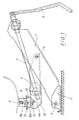
- the jack consists of a pedestal 1, at the lower end of which a foot 2 is articulated about a transverse axis 3 and in the central region of which a support arm 4 is also articulated about a transverse axis 5 .
- Its free end 4a can be adjusted in height by means of a spindle drive 7 which can be actuated by a hand crank 6.
- a load holder 8 is attached to it, which, when attached, engages under a component of the vehicle to be lifted, for example a body sill seam web 9, which is intended to be supported on the jack.
- the connection of the load bearing 8 to the free end 4a of the support arm 4 is designed like a ball joint.
- the load holder 8 is designed as an injection molded part made of plastic. It has on its upper side a transversely running channel 8a, in which the underpinned vehicle part, for example body sill seam web 9, rests. On its underside it has a bearing shoulder 8b in the form of a spherical section. This lies in a bearing shell 10 arranged at the free end 4a of the support arm 4 in the form of a dome congruent with the bearing shoulder 8b . This is designed as a steel sheet molded part and welded to the end of the support arm.
- An opening 11 is provided in the central region of the bearing shell 10 , while a downward-pointing connecting bolt 12 is arranged in the bearing shoulder 8b of the load receiver 8 .
- the cross section of the opening 11 in the bearing shell 10 is larger than the cross section of the connecting bolt 12 and has one in the direction of the support arm 4 elongated oval shape.
- the end of the connecting bolt 12 protrudes through the opening 11 at the bottom out of the bearing shell 10 and is provided with an abutment 13 which is supported on the underside of the bearing shell 10 and is in the form of a disk which is fixed to the connecting bolt 12 by riveting the bolt end.
- the other end of the connecting bolt 12 is cast into the load holder and thus firmly anchored in it.
- the bearing boss 8b of the load bearing 8 is clad with a spherical cap 81 designed as a sheet steel molded part.
- the bearing shell 10 is welded with its lower part into the support arm 4, which is designed as an upwardly open U-profile, between the profile side legs in bulges thereof.
- Fig. 4 shows another embodiment, wherein the bearing shell 10 ' in two opposite circumferential areas in the direction of the support arm 4 has a downwardly curved edge 10'b , with which it is on the edges of the profile side legs of the U-profile open as upwards trained support arm 4 is welded.
Landscapes
- Life Sciences & Earth Sciences (AREA)
- Engineering & Computer Science (AREA)
- Geology (AREA)
- Mechanical Engineering (AREA)
- Structural Engineering (AREA)
- Vehicle Cleaning, Maintenance, Repair, Refitting, And Outriggers (AREA)
- Body Structure For Vehicles (AREA)
- Forklifts And Lifting Vehicles (AREA)
- Vehicle Body Suspensions (AREA)
- Valve Device For Special Equipments (AREA)
- Valve-Gear Or Valve Arrangements (AREA)
- Conveying And Assembling Of Building Elements In Situ (AREA)
- Magnetic Heads (AREA)
- Auxiliary Devices For Music (AREA)
- Surgical Instruments (AREA)
- Control Of Motors That Do Not Use Commutators (AREA)
- Jib Cranes (AREA)
Description
- Die Erfindung betrifft einen Wagenheber mit einer Standsäule, an deren unterem Ende ein Fuß um eine Querachse schwenkbar angelenkt ist und in deren Mittelbereich ein Tragarm ebenfalls um eine Querachse schwenkbar angelenkt ist, dessen freies Ende mittels eines durch Handkurbel betätigten Spindeltriebes höhenverstellbar ist und auf Lagerflächen mit teilkreisförmigem Querschnitt eine kippbar gelagerte Lastaufnahme mit zur Lagerung kongruent geformter Basis trägt, wobei die Lastaufnahme zum Untergreifen eines Karosserie-Schwellernahtsteges oder dergleichen Bauteil eine nach oben offene, parallel zur Schwenkachse des Tragarms verlaufende Rinne aufweist.
- Aus der GB-A-2176 458 geht ein Wagenheber mit diesen Gattungsmerkmalen hervor. Ein wesentlicher Teil dieser Merkmale sind dort als Stand der Technik beschrieben worden. Bei dem durch diese Patentschrift bekannt gewordenen Wagenheber ist der Fuß am unteren Ende der Standsäule unbeweglich befestigt.
Es sind indessen aber auch Wagenheber im Verkehr und daher allgemein bekannt, wobei der Fuß um eine Querachse beweglich an der Standsäule angelenkt ist. - Bei dem Wagenheber gemäß der vorgenannten Patentschrift ist der Tragarm als oben offenes U-Profil ausgebildet. Für die Lagerung der als Horn bezeichneten Lastaufnahme besitzen die Seitenschenkel des U-Profils am Ende des Tragarmes Ausnehmungen in Form von in die Profil-Seitenschenkel eingeformten, teilkreisförmigen Lagerflächen, die jeweils eine Lagerschale mit sehr schmalen Lagerflächen bilden.
Das sogenannte Horn - die Lastaufnahme - ist einstückig aus einem Blechformteil hergestellt, welches einen im Querschnitt teilkreisförmig gestalteten Mantel bildet, der oben eine als Lastaufnahme dienende Nut freiläßt. Das Horn ist mit seinen Stirnendbereichen in den die Lagerflächen bildenden Ausnehmungen der Tragarm-Seitenschenkel um seine Längsachse innerhalb eines bestimmten Kreissektors verdrehbar gelagert und gegen Herauslösen aus seiner Lagerung stirnseitig gesichert.
Von dem Mantel des Horns stehen nach außen oder nach innen abgewinkelte Lappen ab, die der Abstützung eines Karosserie-Schwellernahtsteges dienen. Mit dieser Formgebung des als Lastaufnahme des Wagenhebers dienenden Horns soll die Aufgabe erfüllt werden, bei einem derartigen Wagenheber einen möglichst kleinen Abstand der Last tragenden Horn-Oberseite von der Querachse, um die sich das Horn drehen läßt, zu bewerkstelligen. - Ein solcher Wagenheber ist in der Herstellung zwar sehr einfach und billig. Für diese Billigkeit müssen jedoch Nachteile beim Gebrauch hingenommen werden:
Der Wagenheber wird mit sehr weit geneigter Standsäule eingesetzt. In der "Oben"-Stellung hingegen steht sie wesentlich steiler. Dabei soll sie aber sowohl in der stark geneigten Einsatz-Stellung, als in der nur schwach geneigten "Oben"-Stellung einen sicheren Stand haben. Um dieser Bedingung wenigstens einigermaßen nahe zu kommen, ist der unbeweglich am unteren Ende der Standsäule befestigte Fuß mit zwei in einem stumpfen Winkel aneinanderstoßenden Standflächen versehen. Die eine Standfläche liegt in der Einsatz-Stellung des Wagenhebers flach auf dem Boden, während die andere Standfläche in der "Oben"-Stellung flach auf dem Boden aufliegt. Während des Hebevorganges kippt die Standsäule von der einen Standfläche über die Winkelkante auf die andere Standfläche, was einen unsicheren Stand des Wagenhebers während des Hebevorganges zur Folge hat. - Hinzu kommt, daß die als Horn bezeichnete Lastaufnahme des Wagenhebers nicht um die Querachse des anzuhebenden Fahrzeuges beweglich ist. Beim Anheben des Fahrzeuges in einem Radbereich wird es an der betreffenden Seite um seine Querachse geneigt. Dieser Neigung kann der Wagenheber nur dadurch folgen, daß sich auch die Standsäule gegen das nicht angehobene Rad der gleichen Fahrzeugseite neigt, was zu einer weiteren Beeinträchtigung der Standsicherheit des Wagenhebers führt.
- Ein weiteres, ebenfalls bei häufiger Benutzung die Sicherheit des Wagenhebers beeinträchtigendes Merkmal ist die Lagerung des Horns. Es ist auf den nur sehr schmalen Schnittflächen in den Seitenschenkeln des U-Profils gelagert, aus dem der Tragarm besteht.
- Es entsteht also ein großer Flächendruck, mit dem das Horn bei seiner Drehung während des Hebevorganges auf seinen Lagerflächen reibt. Das kann bei häufiger Benutzung über einen längeren Zeitraum hinaus unter Rostbildung zu vorzeitiger Unbrauchbarkeit des Wagenhebers führen.
- Nun ist ein solcher Wagenheber zwar ein Zubehör, welches normalerweise nur selten oder gar nicht benutzt wird, wenn man die jahreszeitlich bedingten Radwechsel in der Werkstatt durchführen läßt. Er sollte daher möglichst billig sein.
Andererseits aber kann sich ein auch in schwierigem Gelände leicht zu handhabender und funktionssicherer Wagenheber schon bei seltenem Gebrauch bezahlt machen, wenn auf Reisen Radwechsel erforderlich sind. - Der Erfindung liegt daher die Aufgabe zugrunde, einen Wagenheber zu schaffen, der einerseits einfach in seiner Konstruktion und billig herstellbar ist, der aber andererseits eine hohe Gebrauchssicherheit auch bei häufigem Gebrauch über einen längeren Zeitraum und eine leichte Handhabung gewährleistet. Dabei wird besonders Wert darauf gelegt, daß der Wagenheber auch auf unebenem Boden in jeder Stellung während eines Hebevorganges einen sicheren Stand hat und die Lastaufnahme am Ende des Tragarmes verkantungsfrei den für den Ansatz des Wagenhebers vorgesehenen Abschnitt des Karosserie-Schwellernahtsteges untergreift.
- Diese Aufgabe wird erfindungsgemäß dadurch gelöst, daß ein Wagenheber der in der Beschreibungseinleitung und im Oberbegriff des Anspruchs 1 definierten Gattung mit den Merkmalen gemäß dem Kennzeichen des Anpsruchs 1 ausgestattet ist.
- Weitere Merkmale der Erfindung und alternative Detail-Lösungsvorschläge gehen aus den Ansprüchen 2 bis 8 hervor.
- Die an sich bekannte gelenkige Verbindung des Fußes mit der Standsäule in Verbindung mit der kugelgelenkartigen Verbindung der Lastaufnahme am Ende des Tragarmes bringt den Vorteil, daß der Wagenheber auch auf unebenem Boden während des ganzen Hebevorganges fest und sicher steht. Die kugelgelenkartige Ausbildung der Verbindung der Lastaufnahme mit dem Ende des Tragarmes bringt den Vorteil, daß sich die während des Hebevorganges zunehmende Neigung der angehobenen Fahrzeugseite um die Fahrzeug-Querachse sich nicht nachteilig auf die Standsicherheit des Wagenhebers und auf die Verbindung der Lastaufnahme mit dem untergriffenen Fahrzeugteil auswirkt.
- Die großflächige Lagerung der Lastaufnahme am Ende des Tragarmes verhindert Reibungsschäden an den Berührungsflächen dieser beiden Teile. Dabei gewährleistet der ovale Durchbruch im Boden der kalottenförmigen Lagerfläche am Tragarm, daß die Lastaufnahme in ihrem Lager den Neigungen des angehobenen Fahrzeuges sowohl um dessen Längsachse, als auch um dessen Querachse folgen kann. Dadurch hat sie stets eine verkantungsfreie Verbindung mit dem untergriffenen Fahrzeugteil, z.B. dem Karosserie-Schwellernahtsteg.
- Die Erfindung wird im Folgenden anhand einer sie beispielsweise wiedergebenden Zeichnung näher erläutert. Es zeigen:
- Fig. 1
- einen erfindungsgemäßen Wagenheber in Ansatzstellung von der Seite gesehen;
- Fig. 2
- einen senkrechten Längsschnitt durch das freie Tragarmende mit der Lastaufnahme in vergrößerter Darstellung;
- Fig. 3
- einen Querschnitt nach der Linie A - A in Fig. 2;
- Fig. 4
- einen senkrechten Längsschnitt durch das freie Tragarmende mit einer anderen Ausführungsform der Lagerung und Ausbildung der Lastaufnahme.
- Der Wagenheber besteht aus einer Standsäule 1, an deren unterem Ende ein Fuß 2 um eine Querachse 3 schwenkbar angelenkt ist und in deren Mittelbereich ein Tragarm 4 ebenfalls um eine Querachse 5 schwenkbar angelenkt ist. Dessen freies Ende 4a ist mittels eines durch eine Handkurbel 6 betätigbaren Spindeltriebes 7 höhenverstellbar An ihm ist eine Lastaufnahme 8 befestigt, die beim Ansatz ein zur Abstützung auf dem Wagenheber bestimmtes Bauteil des zu hebenden Fahrzeuges, z.B. einen Karosserie-Schwellernahtsteg 9 untergreift. Die Verbindung der Lastaufnahme 8 mit dem freien Ende 4a des Tragarmes 4 ist kugelgelenkartig ausgebildet.
- Die Lastaufnahme 8 ist als Spritzguß-Formteil aus Kunststoff ausgebildet. Sie hat an ihrer Oberseite eine quer verlaufende Rinne 8a, in der das untergriffene Fahrzeugteil, beispielsweise Karosserie-Schwellernahtsteg 9 ruht. An ihrer Unterseite weist sie einen Lageransatz 8b in Form eines Kugelabschnittes auf. Dieser liegt in einer am freien Ende 4a des Tragarmes 4 angeordneten Lagerschale 10 in Form einer zum Lageransatz 8b kongruenten Kalotte. Diese ist als Stahlblech-Formteil ausgebildet und mit dem Tragarmende verschweißt.
- In dem Mittenbereich der Lagerschale 10 ist ein Durchbruch 11 vorgesehen, während in dem Lageransatz 8b der Lastaufnahme 8 ein nach unten gerichteter Verbindungsbolzen 12 angeordnet ist. Der Querschnitt des Durchbruches 11 in der Lagerschale 10 ist größer, als der Querschnitt des Verbindungsbolzens 12 und hat eine in der Richtung des Tragarmes 4 gestreckte ovale Form. Das Ende des Verbindungsbolzens 12 ragt durch den Durchbruch 11 unten aus der Lagerschale 10 heraus und ist mit einem sich an der Unterseite der Lagerschale 10 abstützenden Widerlager 13 in Form einer Scheibe versehen, die durch Vernieten des Bolzenendes an dem Verbindungsbolzen 12 fixiert ist. Das andere Ende des Verbindungsbolzens 12 ist in die Lastaufnahme eingegossen und so in dieser fest verankert.
- Während bei der Ausführungsform gem. Fig. 1 bis 3 der Lageransatz 8b unmittelbar in der Lagerschale 10 ruht, ist bei der in Fig. 4 dargestellten Ausführungsform der Lageransatz 8b der Lastaufnahme 8 mit einer als Stahlblech-Formteil ausgebildeten Kalotte 81 bekleidet.
- Bei der in den Fig. 1 bis 3 dargestellten Ausführungsform ist die Lagerschale 10 mit ihrem unteren Teil in den als nach oben offenes U-Profil ausgebildeten Tragarm 4 hineinreichend zwischen den Profil-Seitenschenkeln in Auswölbungen derselben eingeschweißt. Fig. 4 zeigt eine andere Ausführungsform, wobei die Lagerschale 10' in zwei in der Richtung des Tragarmes 4 einander gegenüberliegenden Umfangsbereichen einen abwärtsgewölbten Rand 10'b hat, mit dem sie auf den Rändern der Profil-Seitenschenkel des als nach oben offenes U-Profil ausgebildeten Tragarmes 4 festgeschweißt ist.
Claims (8)
- Wagenheber mit einer Standsäule, an deren unterem Ende ein Fuß um eine Querachse schwenkbar angelenkt ist und in deren Mittelbereich ein Tragarm ebenfalls um eine Querachse schwenkbar angelenkt ist, dessen freies Ende mittels eines durch Handkurbel betätigbaren Spindeltriebes höhenverstellbar ist und auf Lagerflächen mit teilkreisförmigem Querschnitt eine kippbar gelagerte Lastaufnahme mit zur Lagerung kongruent geformter Basis trägt, wobei die Lastaufnahme zum Untergreifen eines für die Abstützung des Fahrzeuges auf dem Wagenheber vorgesehenen Bauteils, insbesondere eines Karosserie-Schwellernahtsteges eine nach oben offene, parallel zur Schwenkachse des Tragarmes verlaufende Rinne aufweist,
dadurch gekennzeichnet,
daß die Verbindung der Lastaufnahme (8) am freien Ende (4a) des Tragarmes (4) kugelgelenkartig ausgebildet ist, wobeia) die Lastaufnahme (8) an ihrer Unterseite einen Lageransatz (8b) in Form eines Kugelabschnittes aufweist, während am freien Ende (4a) des Tragarmes (4) eine Lagerschale (10) in Form einer zum Lageransatz (8b) der Lastaufnahme (8) kongruenten Kalotte angeordnet ist und wobeib) im Mittenbereich der Lagerschale (10) ein Durchbruch (11) vorgesehen ist, während in dem Lageransatz (8b) der Lastaufnahme (8) ein nach unten gerichteter Verbindungsbolzen (12) angeordnet ist, dessen Querschnitt kleiner ist, als der Querschnitt des Durchbruches (11) in der Lagerschale (10) und der an seinem unteren, aus der Lagerschale (10) herausragenden Ende ein sich an der Unterseite der Lagerschale (10) abstützendes Widerlager (13) hat. - Wagenheber nach Anspruch 1,
dadurch gekennzeichnet,
daß die Lastaufnahme (8) mit dem Lageransatz (8b) einstückig als Spritzguß-Formteil aus Kunststoff ausgebildet ist, in das der Verbindungsbolzen (12) eingegossen ist. - Wagenheber nach den Ansprüchen 1 und 2,
dadurch gekennzeichnet,
daß der Durchbruch (11) in der Lagerschale (10) am Ende des Tragarmes (4) eine in der Richtung des Tragarmes (4) gestreckte ovale Form hat. - Wagenheber nach einem der Ansprüche 1 bis 3,
dadurch gekennzeichnet,
daß das Widerlager (13) am Ende des Verbindungsbolzens (12) an der Lastaufnahme (8) eine mit an sich bekannten Mitteln fixierte, die Ränder des Durchbruches (11) in der Lagerschale (10) wenigstens seitlich untergreifende Metallscheibe ist. - Wagenheber nach einem der Ansprüche 1 bis 4,
dadurch gekennzeichnet,
daß der Lageransatz (8b) der Lastaufnahme (8) mit einer als Stahlblech-Formteil ausgebildeten Kalotte (81) bekleidet ist. - Wagenheber nach einem der Ansprüche 1 bis 5,
dadurch gekennzeichnet,
daß die am freien Ende (4a) des Tragarmes (4) angeordnete Lagerschale (10) für die Lastaufnahme (8) als Stahlblech-Formteil ausgebildet und mit dem Tragarm (4) verschweißt ist. - Wagenheber nach einem der Ansprüche 1 bis 6,
dadurch gekennzeichnet,
daß die Lagerschale (10) mit ihrem unteren Teil in den als nach oben offenes U-Profil ausgebildeten Tragarm (4) hineinragend zwischen den Profil-Seitenschenkeln in Auswölbungen derselben eingeschweißt ist. - Wagenheber nach einem der Ansprüche 1 bis 6,
dadurch gekennzeichnet,
daß die Lagerschale (10') wenigstens in zwei einander gegenüberliegenden Umfangsbereichen einen abwärtsgewölbten Rand (10'b) hat, mit dem sie auf den Rändern der Profil-Seitenschenkel des als nach oben offenes U-Profil ausgebildeten Tragarms (4) festgeschweißt ist.
Priority Applications (1)
| Application Number | Priority Date | Filing Date | Title |
|---|---|---|---|
| AT91101741T ATE91113T1 (de) | 1990-02-21 | 1991-02-08 | Wagenheber. |
Applications Claiming Priority (2)
| Application Number | Priority Date | Filing Date | Title |
|---|---|---|---|
| DE4005447A DE4005447A1 (de) | 1990-02-21 | 1990-02-21 | Wagenheber |
| DE4005447 | 1990-02-21 |
Publications (2)
| Publication Number | Publication Date |
|---|---|
| EP0443383A1 EP0443383A1 (de) | 1991-08-28 |
| EP0443383B1 true EP0443383B1 (de) | 1993-06-30 |
Family
ID=6400656
Family Applications (1)
| Application Number | Title | Priority Date | Filing Date |
|---|---|---|---|
| EP91101741A Expired - Lifetime EP0443383B1 (de) | 1990-02-21 | 1991-02-08 | Wagenheber |
Country Status (9)
| Country | Link |
|---|---|
| US (1) | US5125627A (de) |
| EP (1) | EP0443383B1 (de) |
| JP (1) | JPH08188391A (de) |
| KR (1) | KR910021336A (de) |
| AT (1) | ATE91113T1 (de) |
| CA (1) | CA2036849A1 (de) |
| DE (2) | DE4005447A1 (de) |
| ES (1) | ES2042316T3 (de) |
| HU (1) | HU205324B (de) |
Families Citing this family (6)
| Publication number | Priority date | Publication date | Assignee | Title |
|---|---|---|---|---|
| US5228651A (en) * | 1990-10-22 | 1993-07-20 | The United States Of America As Represented By The Secretary Of The Army | Roll up jack stand |
| DE69222755T3 (de) * | 1992-04-14 | 2001-03-15 | Aries Industries Mecanismes Et Decoupage Fin S.A., Poissy | Wagenheber |
| ES1024192Y (es) * | 1993-03-30 | 1994-04-16 | Tub Sa | Dispositivo estabilizador automatico y de refuerzo para gatos elevadores. |
| EP0749936B1 (de) * | 1995-06-20 | 2004-08-11 | ThyssenKrupp Bilstein GmbH | Wagenheber |
| ITUA20161383A1 (it) * | 2016-03-04 | 2017-09-04 | Brasola S R L | Sollevatore per veicoli. |
| CN114801279B (zh) * | 2022-04-27 | 2023-02-03 | 金丰(中国)机械工业有限公司 | 一种多点压力机的曲轴相位调整方法 |
Family Cites Families (9)
| Publication number | Priority date | Publication date | Assignee | Title |
|---|---|---|---|---|
| GB155084A (en) * | 1919-10-27 | 1920-12-16 | Edward Moulds | An improved adjustable vice |
| FR531606A (fr) * | 1921-03-03 | 1922-01-17 | Cric hydraulique | |
| FR546204A (fr) * | 1922-01-09 | 1922-11-03 | Cric | |
| US2613440A (en) * | 1950-03-20 | 1952-10-14 | Addie P Murray | Articulator for making artificial dentures |
| US2997762A (en) * | 1958-07-25 | 1961-08-29 | Jack G Imparato | Clamp units |
| GB2053846B (en) * | 1979-07-12 | 1983-03-09 | Metallifacture Ltd | Vehicle jacks |
| AT375621B (de) * | 1980-11-03 | 1984-08-27 | Voest Alpine Ag | Schraubengetriebe, insbesondere schraubenwinde |
| DE3111861C2 (de) * | 1981-03-26 | 1983-01-05 | Gerd 5000 Köln Natt | Vorrichtung zum Befestigen von mit einem Sockel versehenen Gebißmodellen am Modellträger eines Artikulators |
| GB2176458B (en) * | 1985-05-10 | 1989-07-05 | Metallifacture Ltd | Vehicle jack |
-
1990
- 1990-02-21 DE DE4005447A patent/DE4005447A1/de not_active Withdrawn
-
1991
- 1991-02-08 DE DE9191101741T patent/DE59100168D1/de not_active Expired - Fee Related
- 1991-02-08 EP EP91101741A patent/EP0443383B1/de not_active Expired - Lifetime
- 1991-02-08 ES ES199191101741T patent/ES2042316T3/es not_active Expired - Lifetime
- 1991-02-08 AT AT91101741T patent/ATE91113T1/de not_active IP Right Cessation
- 1991-02-20 HU HU91562A patent/HU205324B/hu not_active IP Right Cessation
- 1991-02-20 JP JP3026239A patent/JPH08188391A/ja not_active Withdrawn
- 1991-02-20 KR KR1019910002677A patent/KR910021336A/ko not_active Withdrawn
- 1991-02-21 CA CA002036849A patent/CA2036849A1/en not_active Abandoned
- 1991-02-21 US US07/658,992 patent/US5125627A/en not_active Expired - Fee Related
Also Published As
| Publication number | Publication date |
|---|---|
| ATE91113T1 (de) | 1993-07-15 |
| HUT56789A (en) | 1991-10-28 |
| HU205324B (en) | 1992-04-28 |
| JPH08188391A (ja) | 1996-07-23 |
| HU910562D0 (en) | 1991-09-30 |
| DE59100168D1 (de) | 1993-08-05 |
| ES2042316T3 (es) | 1993-12-01 |
| KR910021336A (ko) | 1991-12-20 |
| EP0443383A1 (de) | 1991-08-28 |
| US5125627A (en) | 1992-06-30 |
| DE4005447A1 (de) | 1991-08-22 |
| CA2036849A1 (en) | 1991-08-22 |
Similar Documents
| Publication | Publication Date | Title |
|---|---|---|
| DE69809470T2 (de) | Hebevorrichtung mit einer hebbaren und kippbaren plattform | |
| EP0443383B1 (de) | Wagenheber | |
| DE8327663U1 (de) | Kappsaege | |
| DE3700885A1 (de) | Auto-dachtraeger mit wenigstens einem zwischen einer gebrauchsstellung und einer nichtgebrauchsstellung schwenkbaren halteteil | |
| DE9200472U1 (de) | Gepäckstückrolle | |
| EP0232836B1 (de) | Spindelwagenheber | |
| DE2333199C3 (de) | Befestigungsanordnung einer Laufrolle am Gestell eines Transportwagens | |
| DE3429636C2 (de) | ||
| DE9002560U1 (de) | Wagenheber | |
| DE2910210C2 (de) | Wagenheber | |
| DE3510196C2 (de) | Wagenheber | |
| DE10326708A1 (de) | Hubwagen, insbesondere Gabelhubwagen | |
| DE3608003C2 (de) | ||
| DE3111694C2 (de) | Fahrbarer Montagebock | |
| DE3306789C2 (de) | ||
| EP0749936A2 (de) | Wagenheber | |
| EP0864464A2 (de) | Zusammenlegbares Warndreieck | |
| DE69100009T2 (de) | Wagenheber. | |
| DE3642972C2 (de) | Wagenheber | |
| DE10022448A1 (de) | Außenrückblickspiegel für Fahrzeuge, vorzugseise für Kraftfahrzeuge | |
| DE19741742A1 (de) | Gabelhubwagen mit Stützrad | |
| DE3206756C2 (de) | Vorrichtung zum fahrzeugseitigen Anschluß mindestens einer Stabilisierungsstrebe für die Seitenstabilisierung der Unterlenker eines Dreipunktgestänges | |
| EP0382883A2 (de) | Gelenkiger Trägerkopf für einen Schleifteller | |
| DE4238052C2 (de) | Wagenheber | |
| DE2852014C2 (de) |
Legal Events
| Date | Code | Title | Description |
|---|---|---|---|
| PUAI | Public reference made under article 153(3) epc to a published international application that has entered the european phase |
Free format text: ORIGINAL CODE: 0009012 |
|
| AK | Designated contracting states |
Kind code of ref document: A1 Designated state(s): AT BE CH DE DK ES FR GB GR IT LI LU NL SE |
|
| 17P | Request for examination filed |
Effective date: 19910816 |
|
| 17Q | First examination report despatched |
Effective date: 19920626 |
|
| RAP1 | Party data changed (applicant data changed or rights of an application transferred) |
Owner name: JOHNSON CONTROLS LAHNWERK GMBH & CO. KG. |
|
| RAP1 | Party data changed (applicant data changed or rights of an application transferred) |
Owner name: AUGUST BILSTEIN GMBH & CO KG |
|
| GRAA | (expected) grant |
Free format text: ORIGINAL CODE: 0009210 |
|
| AK | Designated contracting states |
Kind code of ref document: B1 Designated state(s): AT BE CH DE DK ES FR GB GR IT LI LU NL SE |
|
| PG25 | Lapsed in a contracting state [announced via postgrant information from national office to epo] |
Ref country code: GR Free format text: LAPSE BECAUSE OF FAILURE TO SUBMIT A TRANSLATION OF THE DESCRIPTION OR TO PAY THE FEE WITHIN THE PRESCRIBED TIME-LIMIT Effective date: 19930630 |
|
| REF | Corresponds to: |
Ref document number: 91113 Country of ref document: AT Date of ref document: 19930715 Kind code of ref document: T |
|
| REF | Corresponds to: |
Ref document number: 59100168 Country of ref document: DE Date of ref document: 19930805 |
|
| GBT | Gb: translation of ep patent filed (gb section 77(6)(a)/1977) |
Effective date: 19930730 |
|
| ET | Fr: translation filed | ||
| ITF | It: translation for a ep patent filed | ||
| REG | Reference to a national code |
Ref country code: GR Ref legal event code: FG4A Free format text: 3009088 |
|
| REG | Reference to a national code |
Ref country code: ES Ref legal event code: FG2A Ref document number: 2042316 Country of ref document: ES Kind code of ref document: T3 |
|
| PGFP | Annual fee paid to national office [announced via postgrant information from national office to epo] |
Ref country code: BE Payment date: 19940114 Year of fee payment: 4 |
|
| PG25 | Lapsed in a contracting state [announced via postgrant information from national office to epo] |
Ref country code: DK Effective date: 19940208 Ref country code: AT Effective date: 19940208 |
|
| PG25 | Lapsed in a contracting state [announced via postgrant information from national office to epo] |
Ref country code: SE Effective date: 19940209 |
|
| PG25 | Lapsed in a contracting state [announced via postgrant information from national office to epo] |
Ref country code: LU Free format text: LAPSE BECAUSE OF NON-PAYMENT OF DUE FEES Effective date: 19940228 Ref country code: LI Effective date: 19940228 Ref country code: CH Effective date: 19940228 |
|
| PLBE | No opposition filed within time limit |
Free format text: ORIGINAL CODE: 0009261 |
|
| STAA | Information on the status of an ep patent application or granted ep patent |
Free format text: STATUS: NO OPPOSITION FILED WITHIN TIME LIMIT |
|
| 26N | No opposition filed | ||
| PG25 | Lapsed in a contracting state [announced via postgrant information from national office to epo] |
Ref country code: NL Effective date: 19940901 |
|
| NLV4 | Nl: lapsed or anulled due to non-payment of the annual fee | ||
| REG | Reference to a national code |
Ref country code: CH Ref legal event code: PL |
|
| REG | Reference to a national code |
Ref country code: GR Ref legal event code: MM2A Free format text: 3009088 |
|
| EUG | Se: european patent has lapsed |
Ref document number: 91101741.6 Effective date: 19940910 |
|
| PG25 | Lapsed in a contracting state [announced via postgrant information from national office to epo] |
Ref country code: BE Effective date: 19950228 |
|
| BERE | Be: lapsed |
Owner name: AUGUST BILSTEIN G.M.B.H. & CO. K.G. Effective date: 19950228 |
|
| PGFP | Annual fee paid to national office [announced via postgrant information from national office to epo] |
Ref country code: GB Payment date: 19970113 Year of fee payment: 7 |
|
| PGFP | Annual fee paid to national office [announced via postgrant information from national office to epo] |
Ref country code: FR Payment date: 19970114 Year of fee payment: 7 |
|
| PGFP | Annual fee paid to national office [announced via postgrant information from national office to epo] |
Ref country code: DE Payment date: 19970124 Year of fee payment: 7 |
|
| PGFP | Annual fee paid to national office [announced via postgrant information from national office to epo] |
Ref country code: ES Payment date: 19970218 Year of fee payment: 7 |
|
| PG25 | Lapsed in a contracting state [announced via postgrant information from national office to epo] |
Ref country code: GB Free format text: LAPSE BECAUSE OF NON-PAYMENT OF DUE FEES Effective date: 19980208 |
|
| PG25 | Lapsed in a contracting state [announced via postgrant information from national office to epo] |
Ref country code: ES Free format text: LAPSE BECAUSE OF EXPIRATION OF PROTECTION Effective date: 19980209 |
|
| PG25 | Lapsed in a contracting state [announced via postgrant information from national office to epo] |
Ref country code: FR Free format text: THE PATENT HAS BEEN ANNULLED BY A DECISION OF A NATIONAL AUTHORITY Effective date: 19980228 |
|
| GBPC | Gb: european patent ceased through non-payment of renewal fee |
Effective date: 19980208 |
|
| PG25 | Lapsed in a contracting state [announced via postgrant information from national office to epo] |
Ref country code: DE Free format text: LAPSE BECAUSE OF NON-PAYMENT OF DUE FEES Effective date: 19981103 |
|
| REG | Reference to a national code |
Ref country code: FR Ref legal event code: ST |
|
| REG | Reference to a national code |
Ref country code: ES Ref legal event code: FD2A Effective date: 20000301 |
|
| PG25 | Lapsed in a contracting state [announced via postgrant information from national office to epo] |
Ref country code: IT Free format text: LAPSE BECAUSE OF NON-PAYMENT OF DUE FEES;WARNING: LAPSES OF ITALIAN PATENTS WITH EFFECTIVE DATE BEFORE 2007 MAY HAVE OCCURRED AT ANY TIME BEFORE 2007. THE CORRECT EFFECTIVE DATE MAY BE DIFFERENT FROM THE ONE RECORDED. Effective date: 20050208 |