EP0442650A2 - Plattenspeicher mit adaptiver Korrektur des nichtwiederholenden Rundlauffehlers der Platte - Google Patents
Plattenspeicher mit adaptiver Korrektur des nichtwiederholenden Rundlauffehlers der Platte Download PDFInfo
- Publication number
- EP0442650A2 EP0442650A2 EP91300945A EP91300945A EP0442650A2 EP 0442650 A2 EP0442650 A2 EP 0442650A2 EP 91300945 A EP91300945 A EP 91300945A EP 91300945 A EP91300945 A EP 91300945A EP 0442650 A2 EP0442650 A2 EP 0442650A2
- Authority
- EP
- European Patent Office
- Prior art keywords
- nrro
- signal
- pes
- disk
- digital
- Prior art date
- Legal status (The legal status is an assumption and is not a legal conclusion. Google has not performed a legal analysis and makes no representation as to the accuracy of the status listed.)
- Granted
Links
- 230000003044 adaptive effect Effects 0.000 title description 3
- 238000005070 sampling Methods 0.000 claims abstract description 6
- 230000000694 effects Effects 0.000 abstract description 3
- 230000006870 function Effects 0.000 description 25
- 238000000034 method Methods 0.000 description 4
- 230000000712 assembly Effects 0.000 description 3
- 238000000429 assembly Methods 0.000 description 3
- 238000013461 design Methods 0.000 description 3
- 238000001514 detection method Methods 0.000 description 3
- 238000009795 derivation Methods 0.000 description 2
- 238000010586 diagram Methods 0.000 description 2
- 238000002474 experimental method Methods 0.000 description 2
- 230000001360 synchronised effect Effects 0.000 description 2
- 238000012360 testing method Methods 0.000 description 2
- 230000001133 acceleration Effects 0.000 description 1
- 239000012190 activator Substances 0.000 description 1
- 230000006399 behavior Effects 0.000 description 1
- 230000014509 gene expression Effects 0.000 description 1
- 238000010348 incorporation Methods 0.000 description 1
- 238000012545 processing Methods 0.000 description 1
- 230000003252 repetitive effect Effects 0.000 description 1
Images

Classifications
-
- G—PHYSICS
- G11—INFORMATION STORAGE
- G11B—INFORMATION STORAGE BASED ON RELATIVE MOVEMENT BETWEEN RECORD CARRIER AND TRANSDUCER
- G11B21/00—Head arrangements not specific to the method of recording or reproducing
- G11B21/02—Driving or moving of heads
- G11B21/10—Track finding or aligning by moving the head ; Provisions for maintaining alignment of the head relative to the track during transducing operation, i.e. track following
- G11B21/106—Track finding or aligning by moving the head ; Provisions for maintaining alignment of the head relative to the track during transducing operation, i.e. track following on disks
-
- G—PHYSICS
- G11—INFORMATION STORAGE
- G11B—INFORMATION STORAGE BASED ON RELATIVE MOVEMENT BETWEEN RECORD CARRIER AND TRANSDUCER
- G11B5/00—Recording by magnetisation or demagnetisation of a record carrier; Reproducing by magnetic means; Record carriers therefor
- G11B5/48—Disposition or mounting of heads or head supports relative to record carriers ; arrangements of heads, e.g. for scanning the record carrier to increase the relative speed
- G11B5/58—Disposition or mounting of heads or head supports relative to record carriers ; arrangements of heads, e.g. for scanning the record carrier to increase the relative speed with provision for moving the head for the purpose of maintaining alignment of the head relative to the record carrier during transducing operation, e.g. to compensate for surface irregularities of the latter or for track following
- G11B5/596—Disposition or mounting of heads or head supports relative to record carriers ; arrangements of heads, e.g. for scanning the record carrier to increase the relative speed with provision for moving the head for the purpose of maintaining alignment of the head relative to the record carrier during transducing operation, e.g. to compensate for surface irregularities of the latter or for track following for track following on disks
- G11B5/59627—Aligning for runout, eccentricity or offset compensation
Definitions
- This invention relates to servo control systems for read/write head positioning in data recording disk files. More particularly, the invention relates to a digital servo control system wherein nonrepeatable movement of the disks relative to the heads is estimated and cancelled by generation of an appropriate control signal.
- Disk files are information storage devices which utilise a rotatable disk with concentric data tracks containing the information, a head for reading or writing data onto the various tracks, and an actuator connected by a support arm assembly to the head for moving the head to the desired track and maintaining it over the track centreline during read or write operations.
- high capacity disk files there are typically a plurality of disks stacked on a hub which is attached to a rotatable shaft.
- the shaft or spindle is driven by the disk drive motor and is supported at its ends by bearing assemblies which are mounted to the disk file housing.
- the data on the disks are accessed by heads which are part of head-arm assemblies connected to the actuator.
- multiple actuators may be used to position the heads to their respective disks in the stack.
- the movement of the head to a desired track is referred to as track accessing or "seeking”, while the maintaining of the head over the centreline of the desired track during a read or write operation is referred to as track "following".
- the actuator is typically a "voice coil motor” (VCM) which comprises a coil movable through the magnetic field of a permanent magnetic stator.
- VCM voice coil motor
- the application of current to the VCM causes the coil, and thus the attached head, to move radially.
- the acceleration of the coil is proportional to the applied current, so that ideally there is no current to the coil if the head is perfectly stationary over a desired track.
- a servo control system In disk files which have a relatively high density of data tracks on the disk, it is necessary to incorporate a servo control system to maintain the head precisely over the centreline of the desired track during read or write operations. This is accomplished by utilising prerecorded servo information either on a dedicated servo disk or on sectors angularly spaced and interspersed among the data on a data disk.
- the servo information sensed by the read/write head (or the dedicated servo head if a dedicated servo disk is used) is demodulated to generate a position error signal (PES) which is an indication of the position error of the head away from the nearest track centreline.
- PES position error signal
- a microprocessor utilises a control signal algorithm to calculate a digital control signal based upon the digital values of certain state variables such as PES, VCM current and head velocity.
- the digital control signal is converted to an analog signal and amplified to provide input current to the VCM.
- Such a digital servo control system is described in U.S. Pat. No. 4,412,161, wherein the digital control signal is calculated recursively from prior control signals and prior values of the PES.
- U.S. Pat. No. 4,679,103 describes a digital servo control system which, as part of the computation of the control signal to the actuator, makes use of a state estimator algorithm to estimate the position and velocity of the head.
- a microprocessor receives, at discrete sample times, digital values corresponding to the PES and the actuator input current, and computes, through the use of the state estimator algorithm, a digital control signal. The digital control signal is then converted to an analog signal and amplified to provide a new actuator input current.
- Nonrepeatable runout does have a dominant sinusoidal behaviour, although the amplitude, frequency and phase (relative to the disk index mark indicating the beginning of a track) of the runout does not repeat from one disk rotation to the next.
- German patent application DE 363465 describes a disk file having a special head which detects nonrepeatable wobble of the spindle from signals recorded on an auxiliary track. The signals from the auxiliary track are used to control the position of the data read/write heads during reading and writing of data on the data tracks.
- disk file apparatus comprises a rotatable disk having substantially concentric data tracks, said disk having servo information recorded thereon; a head for reading said servo information; means for deriving a head position error signal from said servo information; an actuator for controlling the position of said head; and means for supplying said position error signal to digital signal generating means which generate a digital control signal for controlling said activator, characterised in that said digital signal generating means includes a sinusoidal function generator responsive to an input to the said digital signal generating means to compute a non-repeatable runout signal of sinusoidal form which represents the presence of non repeating error in the head position, the digital signal generating means being arranged to incorporate into the said digital control signal a component representative of the non repeatable runout error.
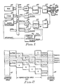
- FIG. 1 there is depicted a simplified block diagram of a digital servo control system.
- a pair of disks 10, 12 is supported on a spindle 14 of the disk file drive motor 16.
- Each of the disks 10, 12 has two surfaces 20, 22 and 24, 26, respectively.
- surface 20 on disk 10 and surfaces 24, 26 on disk 12 are data recording surfaces.
- Surface 22 on disk 10 is a dedicated servo surface and contains only prerecorded servo information.
- the servo information on disk 10 is recorded in concentric tracks, with the position information typically written in such a manner that the intersections of adjacent servo tracks on servo surface 22 are radially aligned with the centrelines of the data tracks on surfaces 20, 24, and 26.
- a conventional quadrature servo pattern is depicted in Fig. 2.
- the servo pattern includes a synchronization area 27, which provides timing information corresponding to the beginning of a set of servo position blocks, and servo block area 29, which provides head position information.
- the specific tracks on the data disks and the servo disk are accessed by heads 30, 32, 34, 36, each of which is associated with a respective disk surface and supported by an associated arm assembly.
- the heads 30, 32, 34, 36 are attached to a common accessing means or actuator, such as VCM 40.
- VCM 40 a common accessing means or actuator
- the signal read by servo head 32 is input to amplifier 42 and then demodulator 44. While the present invention is operable with any of numerous types of servo patterns and servo signal demodulation techniques, the servo control system will be explained with reference to the quadrature servo pattern, as represented in Fig. 2.
- the servo position information in block area 29 in the quadrature pattern on servo surface 22 is demodulated by demodulator 44 to generate two separate analog waveforms, designated primary (PESP) and quadrature (PESQ), as shown in Fig. 1.
- the analog PESP and PESQ signals from demodulator 44 are sent to analog-to-digital (A/D) converters 88, 89, respectively.
- the discrete values of PESP and PESQ at any sample time are designated PESP(n) and PESQ(n), where n represents a time index for each digital sample.
- a microprocessor 80 is connected by data bus 84 and suitable address bus (not shown) to suitable memory devices, such as read/write memory (RAM) 82 and programmable read only memory (PROM) 83.
- Microprocessor 80 utilises a control signal algorithm, as described in U.S. Pat. No. 4,679,103, to generate a control signal u(n).
- the control signal u(n) is output to digital-to-analog converter (DAC) 92 and amplified by power amplifier 98 to generate an analog current i(t) to VCM 40.
- the analog current i(t) is fed back to analog-to-digital (A/D) converter 90, which provides a digital current signal i(n) to microprocessor 80.
- A/D analog-to-digital
- Microprocessor 80 thus receives as inputs, at discrete sample times, the digital actuator current i(n) and the digital head position error signals PESP(n) and PESQ(n).
- U.S. application Ser. No. 249,619 describes a servo control system which does not require feedback of VCM current).
- Microprocessor 80 computes the actual position error signal PES(n) from the values of PESP(n) and PESQ(n), using conventional logic, such as described in the U.S. Pat. No. 4,679,103.
- Also shown as input to microprocessor 80 via data bus 84 is a seek command signal from the disk file control unit (not shown).
- the seek command signal is a digital value which identifies the target track to which the heads are to be re-positioned.
- demodulator 44 demodulates the position information in servo block area 29 from the quadrature servo pattern (Fig. 2) to generate analog PESP and PESQ signals.
- Demodulator 44 also contains synchronization detection circuitry 45 which receives the timing information from the synchronization areas 27 of the quadrature servo pattern and outputs a PES clock signal.
- the PES clock signal is output by synchronization detection circuitry 45 at a frequency corresponding to the rate at which the synchronization areas 27 in the servo pattern pass beneath the servo head 32.
- the PES clock frequency is determined by the number of discrete sets of servo position blocks 29, (and thus the number of corresponding synchronization areas 27) recorded either on the dedicated servo disk or in sectors on the data disk, and the rotational speed of the drive motor 16. Since the number and spacing of recorded synchronization areas 27 are fixed, the PES clock frequency is solely a function of the rotational speed of drive motor 16.
- the PES clock signal synchronization detection circuitry 45 is input to a sampling clock generator 65 which provides an interrupt signal to microprocessor 80.
- Sampling clock generator 65 may be a digital counter which divides the PES clock frequency by a fixed value to provide the interrupt signal at a frequency substantially slower than the PES clock input frequency.
- the digital counter is reset for every revolution of the drive motor 16 by an index mark which is recorded on servo disk surface 22 and which identifies the beginning of a servo track.
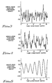
- NRRO The effect of NRRO on the PES pattern can be understood by comparison of Figs. 3 and 4.
- Fig. 3 illustrates a typical PES pattern for one disk rotation without any significant NRRO present. This pattern is highly repetitive from one disk rotation to the next and has a maximum PES amplitude of approximately 50. In Fig. 4, however, the presence of NRRO with a dominant sinusoidal component results in a more erratic PES pattern and one which does not repeat from one disk rotation to the next. In addition the NRRO has increased the PES amplitude from 50 to approximately 100.
- the NRRO present in the PES of Fig. 4 has a dominant sinusoidal component which is illustrated in Fig. 5 for a single disk rotation.
- the microprocessor 80 (Fig.1) generates an estimate of this sinusoidal function and derives a specific NRRO signal which is added to and becomes part of the digital control signal u(n).
- the sinusoidal function must be continually recalculated because, unlike repeatable runout, it varies significantly from one disk rotation to the next, as illustrated in Fig. 6.
- the NRRO sinusoidal function 100 differs in both amplitude and phase (relative to the index mark indicating the beginning of the track) from the NRRO sinusoidal function 101 for the next successive disk rotation. While in Fig.
- Fig. 6 clearly indicates a need to recalculate the NRRO sinusoidal function on a regular basis in order to provide adaptive cancellation of NRRO from the PES.
- MU a , MU b , and MU w are design constants
- PES(n) position error signal at n-th sample
- Term1(n) A(n)*cos[W(n)*t(n)]
- Term2(n) -B(n)*sin[W(n)*t(n)]
- t(n) t(n-1) + PES sampling time.
- the "time" term, t(n) could become arbitrarily large since the control algorithm runs continuously. Thus it is reset to zero at each full period of the estimated NRRO function. This is done whenever the value of t(n) equals or exceeds the estimated period, i.e. 1./[2*PI*W(n)].
- the upper bounds of the design constants (MU a , MU b and MU w ) can be computed based upon the "least mean squares" algorithm described in Adaptive Signal Processing, Widrow, B. and Stearns, S.D., Prentice-Hall, 1985, and expressed as follows as functions of physical parameters of the disk file. In actual implementation, however, experimentally obtained values of MU a , MU b and MU w are used to obtain desirable convergence rates. The method to experimentally determine the MU terms will now be explained. First, a simulated NRRO disturbance with a fixed frequency (W held constant) is injected into the disk file by summing a sinusoidal signal into the PES.
- W held constant a simulated NRRO disturbance with a fixed frequency
- MU w is set equal to zero and initial equal values of MU a and MU b are selected.
- a step change in amplitude of the NRRO (by increasing the values of A and B) is made and the convergence rate of MU a and MU b determined.
- the values of MU a and MU b are incremented and the experiment repeated until instability occurs.
- the desired values of MU a and MU b are then selected.
- To determine MU w a simulated NRRO disturbance with fixed amplitude and phase (A and B held constant) is injected into the disk file.
- An initial value of MU w is selected and its convergence rate is determined by making a step change in frequency of the simulated NRRO disturbance.
- MU w is incremented and the experiment repeated until instability occurs.
- the desired value of MU w is selected.
- An arbitrary simulated sinusoidal NRRO disturbance is then used to determine the performance of the chosen values of MU a , MU b and MU w .
- Fig. 7 the present invention will be explained with respect to the flow chart which describes the method of generation of the NRRO sinusoidal function, the derivation from it of the NRRO signal, and the incorporation of this signal into the control signal to adaptively cancel the NRRO from the PES.
- the digital counter "n" is set to zero and the design constants MU a , MU b and MU w are input from PROM 83 (Fig. 1). Then the PES and the present values of A, B and W are input to microprocessor 80. (Initial values of A, B and W have been previously stored in RAM 82 and are used only for the initial computation of the NRRO signal, u R ).
- the "normal" control signal, u0 representing the control signal without compensation for NRRO, is then computed.
- the actual control signal, u is then computed as the sum of the normal control signal and the NRRO signal, and output to DAC 92.
- decision block 110 if track following is taking place, i.e. no seek command has been received, then changes to A, B and W are computed These changes are the right hand portions of the expressions on the right side of equations 3, 4 and 5, i.e. the amount the A, B and W values have changed from "n-1" to "n". These change values are important to test the rate at which the NRRO is changing. In certain situations the NRRO may rapidly appear and disappear. Thus, decision block 112 tests whether these change values have exceeded an predetermined threshold and, if so, microprocessor 80 sends a command which inhibits the writing of data.
- the time term, t, and the period of the NRRO are computed.
- decision block 114 the time is compared to the estimated period and then reset if it is greater than the period.
- the actual computation of A, B and W according to equations 3, 4 and 5 then occurs. These values are stored in RAM 82.
- the NRRO signal, u R is then computed, after which the digital counter, n, is incremented and the microprocessor 80 is ready for receipt of the next PES.
- the NRRO signal is recalculated for each PES sample by recalculating the terms A, B and W which define the profile of the NRRO.
- Each such profile is uniquely determined by its characteristic amplitude, phase and period, which are functions of A, B and W.
- the NRRO sinusoidal function is adaptively changed between PES samples, so that the NRRO signal which is derived from it and added to the normal control signal is adaptively computed as the NRRO changes.
- a disk file digital servo control system which generates an estimate of the sinusoidal function representative of the dominant sinusoidal component of nonrepeatable runout for one disk rotation and which derives from this function a NRRO signal to add to the digital control signal to eliminate the dominant sinusoidal component of NRRO from the PES.
- the estimate of the sinusoidal function is made from the measured PES and from predetermined constants representative of known disk file physical parameters.
- a new estimate of the sinusoidal function, and accordingly a NRRO signal derived from the newly estimated function is made during every PES sample time during track following.
- the estimate of the NRRO sinusoidal function is not updated during PES sampling; rather the NRRO signal is derived from the last estimate of the sinusoidal function.
- the effect of NRRO on the PES is essentially cancelled, thereby improving the read/write operations of the disk file.
Applications Claiming Priority (2)
| Application Number | Priority Date | Filing Date | Title |
|---|---|---|---|
| US479497 | 1990-02-13 | ||
| US07/479,497 US5072318A (en) | 1990-02-13 | 1990-02-13 | Disk file with adaptive cancellation of nonrepeatable disk runout |
Publications (3)
| Publication Number | Publication Date |
|---|---|
| EP0442650A2 true EP0442650A2 (de) | 1991-08-21 |
| EP0442650A3 EP0442650A3 (en) | 1992-09-09 |
| EP0442650B1 EP0442650B1 (de) | 1997-01-15 |
Family
ID=23904273
Family Applications (1)
| Application Number | Title | Priority Date | Filing Date |
|---|---|---|---|
| EP91300945A Expired - Lifetime EP0442650B1 (de) | 1990-02-13 | 1991-02-05 | Plattenspeicher mit adaptiver Korrektur des nichtwiederholenden Rundlauffehlers der Platte |
Country Status (4)
| Country | Link |
|---|---|
| US (1) | US5072318A (de) |
| EP (1) | EP0442650B1 (de) |
| JP (1) | JP2539951B2 (de) |
| DE (1) | DE69124124T2 (de) |
Cited By (1)
| Publication number | Priority date | Publication date | Assignee | Title |
|---|---|---|---|---|
| EP0777215A2 (de) * | 1995-11-30 | 1997-06-04 | Hewlett-Packard Company | Sinusförmige Verstärkungskorrektur zum Kompensieren der Verstärkungsänderungen eines magnetoresistiven Servokopfes |
Families Citing this family (40)
| Publication number | Priority date | Publication date | Assignee | Title |
|---|---|---|---|---|
| EP0563230B1 (de) * | 1990-12-19 | 2000-02-16 | Mobile Storage Technology Inc. | Miniatur-festplattenantrieb für tragbaren computer |
| US5365458A (en) * | 1991-03-29 | 1994-11-15 | Nippon Densan Corporation | Motor eccentricity measuring apparatus |
| US5379171A (en) * | 1991-09-25 | 1995-01-03 | Integral Peripherals | Microminiature hard disk drive |
| US6310747B1 (en) | 1991-09-25 | 2001-10-30 | Mobile Storage Technology, Inc. | Method for reducing external signal interference with signals in a computer disk storage system |
| WO1993006595A1 (en) * | 1991-09-25 | 1993-04-01 | Integral Peripherals, Inc. | Adaptive runout compensation for miniature disk drives |
| US5402280A (en) * | 1992-05-11 | 1995-03-28 | Quantum Corp. | Method and apparatus for runout correction due to disk slip or spindle imbalance |
| KR0163678B1 (ko) * | 1992-09-09 | 1999-01-15 | 배순훈 | 이득조정 반복학습 제어를 이용한 디스크 드라이브의 헤드위치 제어장치 및 방법 |
| US5615065A (en) * | 1994-10-04 | 1997-03-25 | International Business Machines Corporation | Phase-compensated servo pattern and position error-sensing detector |
| US6091559A (en) | 1994-12-19 | 2000-07-18 | Mobile Storage Technology Inc. | Variable zone layout and track pitch parameter considerations for information storage disk drive |
| US5596458A (en) | 1994-12-19 | 1997-01-21 | Integral Peripherals, Inc. | Variable zone layout for information storage disk drive |
| JPH08306125A (ja) * | 1995-04-28 | 1996-11-22 | Toshiba Corp | 情報記録再生装置 |
| US6456452B1 (en) * | 1995-09-01 | 2002-09-24 | Seagate Technology Llc | Feed forward compensation for repeatable head position error in a disc drive |
| JP2980545B2 (ja) * | 1995-09-25 | 1999-11-22 | インターナショナル・ビジネス・マシーンズ・コーポレイション | デイスク装置およびデイスク装置におけるヘッド位置制御方法 |
| US5793559A (en) * | 1996-02-27 | 1998-08-11 | Quantum Corporation | In drive correction of servo pattern errors |
| US6137753A (en) * | 1997-04-14 | 2000-10-24 | Oak Technology, Inc. | Runout calibration for disc drive system |
| US6014283A (en) * | 1997-05-15 | 2000-01-11 | Western Digital Corporation | Non-quadrature servo burst pattern for micro-jogging a magnetoresistive head in a magnetic disk drive |
| US6064542A (en) * | 1997-08-08 | 2000-05-16 | Quantum Corporation | Methods and apparatus for positioning read/write head in a computer disk drive |
| US6101064A (en) * | 1997-08-08 | 2000-08-08 | Quantum Corporation | Methods and apparatus for efficiently controlling a read/write head in a computer disk drive |
| KR100501692B1 (ko) * | 1998-01-16 | 2005-10-07 | 삼성전자주식회사 | 반복성 런아웃 보상 알고리즘 사용방법 |
| JP3705944B2 (ja) * | 1998-11-27 | 2005-10-12 | 富士通株式会社 | ディスク装置の制御方法及びディスク装置 |
| JP3559209B2 (ja) * | 1998-12-24 | 2004-08-25 | 富士通株式会社 | 記憶装置 |
| US6522495B1 (en) | 1999-04-16 | 2003-02-18 | International Business Machines Corporation | System, method and program for determining the magnetic center shift within a disk drive system |
| US6522493B1 (en) | 1999-04-27 | 2003-02-18 | International Business Machines Corporation | Position error signal linearization using an auxiliary discontinuity removal routine |
| US6421198B1 (en) | 1999-04-27 | 2002-07-16 | International Business Machines Corporation | Linearity compensation for a position error signal based on repeatable and non-repeatable run out in a disk drive |
| US6661599B1 (en) | 1999-08-27 | 2003-12-09 | Seagate Technology Llc | Enhanced adaptive feedforward control to cancel once-per-revolution disturbance by shaping the internal mode |
| US6618219B1 (en) * | 1999-10-12 | 2003-09-09 | Seagate Technology Llc | Method and apparatus for feedforward cancellation using a peak detector |
| US6636376B1 (en) | 1999-10-12 | 2003-10-21 | Seagate Technology Llc | Disc drive resonance disturbance cancellation filter |
| US6628472B1 (en) * | 1999-10-12 | 2003-09-30 | Seagate Technoogy Llc | Method and apparatus for feedforward cancellation using a phase lock loop |
| CN1208758C (zh) * | 2000-06-09 | 2005-06-29 | 西加特技术有限责任公司 | 在磁盘驱动器伺服系统的设定模式期间减小传动器臂振荡 |
| SG104270A1 (en) * | 2000-06-14 | 2004-06-21 | Seagate Technology Llc | Feed-forward compensation of cage frequency using a reference head in a servo-writer |
| US6654198B2 (en) | 2000-08-23 | 2003-11-25 | Seagate Technology Llc | Repeatable run-out error compensation method for a disc drive |
| US6982849B2 (en) * | 2000-09-14 | 2006-01-03 | Samsung Electronics Co., Ltd. | Method and apparatus for providing positional information on a disk |
| US6754030B2 (en) | 2001-06-27 | 2004-06-22 | Seagate Technology Llc | Optimal reader-to-writer offset measurement of a head in a disc drive for reduced track misregistration |
| US6771441B2 (en) | 2001-08-09 | 2004-08-03 | Seagate Technology Llc | Track mis-registration measurement for a disc drive |
| DE10215252B4 (de) * | 2002-04-06 | 2005-06-30 | Minebea Co., Ltd. | Verfahren zur Messung des wiederholbaren und des nicht wiederholbaren Schlages eines rotierenden Bauteils, insbesondere des Rotors eines Spindelmotors, und Vorrichtung zur Durchführung des Verfahrens |
| US7035037B2 (en) * | 2002-06-18 | 2006-04-25 | Seagate Technology Llc | Disc drive with compensation for non-repeatable runout |
| US7057843B2 (en) * | 2003-05-28 | 2006-06-06 | Stmicroelectronics, Inc. | Disk drive control circuit and method |
| KR100585166B1 (ko) * | 2004-12-01 | 2006-06-01 | 삼성전자주식회사 | 비주기적 외란 보상 제어 장치 및 방법과 이를 이용한디스크 드라이브 |
| JP4707006B2 (ja) * | 2007-03-30 | 2011-06-22 | 日本放送協会 | トラッキング制御装置及びそのプログラム、並びに、非周期外乱推定装置及びそのプログラム |
| US7719787B2 (en) * | 2008-02-29 | 2010-05-18 | Seagate Technology Llc | Phase locked anti- notch filter in a servo control loop |
Citations (5)
| Publication number | Priority date | Publication date | Assignee | Title |
|---|---|---|---|---|
| DE363465C (de) * | 1922-11-09 | Siemens & Halske Akt Ges | Schaltungsanordnung fuer Leitungswaehler mit Mehrfachanschluessen | |
| US4589037A (en) * | 1985-03-18 | 1986-05-13 | International Business Machines Corporation | Servo control system using a varying frequency servo pattern for read/write head positioning in a magnetic recording disk file |
| US4616276A (en) * | 1985-07-16 | 1986-10-07 | International Business Machines Corporation | Disk file servo control system with fast reduction of repeatable head position error |
| US4630190A (en) * | 1984-02-21 | 1986-12-16 | Syquest Technology | Servo control apparatus for a disk drive |
| EP0308069A2 (de) * | 1987-09-16 | 1989-03-22 | International Business Machines Corporation | Plattendatei zur Aufnahme von Daten mit digitaler Servosteuerung |
Family Cites Families (3)
| Publication number | Priority date | Publication date | Assignee | Title |
|---|---|---|---|---|
| US4412161A (en) * | 1981-04-24 | 1983-10-25 | Iomega Corporation | Digital control of servo circuit |
| US4679103A (en) * | 1986-04-29 | 1987-07-07 | International Business Machines Corporation | Digital servo control system for a data recording disk file |
| US4939599A (en) * | 1988-02-22 | 1990-07-03 | International Business Machines Corporation | Method and apparatus for measuring dynamic track misregistration |
-
1990
- 1990-02-13 US US07/479,497 patent/US5072318A/en not_active Expired - Lifetime
-
1991
- 1991-01-11 JP JP3002317A patent/JP2539951B2/ja not_active Expired - Lifetime
- 1991-02-05 EP EP91300945A patent/EP0442650B1/de not_active Expired - Lifetime
- 1991-02-05 DE DE69124124T patent/DE69124124T2/de not_active Expired - Lifetime
Patent Citations (5)
| Publication number | Priority date | Publication date | Assignee | Title |
|---|---|---|---|---|
| DE363465C (de) * | 1922-11-09 | Siemens & Halske Akt Ges | Schaltungsanordnung fuer Leitungswaehler mit Mehrfachanschluessen | |
| US4630190A (en) * | 1984-02-21 | 1986-12-16 | Syquest Technology | Servo control apparatus for a disk drive |
| US4589037A (en) * | 1985-03-18 | 1986-05-13 | International Business Machines Corporation | Servo control system using a varying frequency servo pattern for read/write head positioning in a magnetic recording disk file |
| US4616276A (en) * | 1985-07-16 | 1986-10-07 | International Business Machines Corporation | Disk file servo control system with fast reduction of repeatable head position error |
| EP0308069A2 (de) * | 1987-09-16 | 1989-03-22 | International Business Machines Corporation | Plattendatei zur Aufnahme von Daten mit digitaler Servosteuerung |
Cited By (2)
| Publication number | Priority date | Publication date | Assignee | Title |
|---|---|---|---|---|
| EP0777215A2 (de) * | 1995-11-30 | 1997-06-04 | Hewlett-Packard Company | Sinusförmige Verstärkungskorrektur zum Kompensieren der Verstärkungsänderungen eines magnetoresistiven Servokopfes |
| EP0777215A3 (de) * | 1995-11-30 | 1997-12-29 | Hewlett-Packard Company | Sinusförmige Verstärkungskorrektur zum Kompensieren der Verstärkungsänderungen eines magnetoresistiven Servokopfes |
Also Published As
| Publication number | Publication date |
|---|---|
| DE69124124D1 (de) | 1997-02-27 |
| EP0442650A3 (en) | 1992-09-09 |
| US5072318A (en) | 1991-12-10 |
| JPH07326146A (ja) | 1995-12-12 |
| EP0442650B1 (de) | 1997-01-15 |
| JP2539951B2 (ja) | 1996-10-02 |
| DE69124124T2 (de) | 1997-07-17 |
Similar Documents
| Publication | Publication Date | Title |
|---|---|---|
| EP0442650B1 (de) | Plattenspeicher mit adaptiver Korrektur des nichtwiederholenden Rundlauffehlers der Platte | |
| EP0209692B1 (de) | Servoregelungssystem für eine Magnetplattenvorrichtung mit schneller Verminderung des mehrmaligen Kopfpositionsfehlers | |
| EP0243821B1 (de) | Steuerungssystem für scheibenförmigen Aufzeichnungsträger | |
| EP0308070B1 (de) | Datenaufzeichnungs-Plattendatei mit digitaler Nachlaufregelung | |
| US4816941A (en) | Disk file digital servo control system with optimized sampling rate | |
| US5995317A (en) | Method and apparatus for real-time filtering of a position error signal for a disk drive servo system | |
| KR0124052B1 (ko) | 고성능 디스크 드라이브, 이 디스크 드라이브내의 서보 섹터 패턴 및 이 디스크 드라이브에서 데이타 변환기 헤드의 위치를 결정하는 방법 | |
| EP0361786B1 (de) | Digitale Servosteuerung für Plattenspeicher | |
| US6850385B1 (en) | Repeated servo runout error compensation in a disc drive | |
| US5402280A (en) | Method and apparatus for runout correction due to disk slip or spindle imbalance | |
| EP0308069A2 (de) | Plattendatei zur Aufnahme von Daten mit digitaler Servosteuerung | |
| WO2000003389A1 (en) | Current profile shaping to reduce disc drive seek time variation and acoustic noise generation | |
| JPS5933671A (ja) | 磁気ディスク記憶装置のトランスジューサ位置決めシステムおよび位置エラー訂正方法 | |
| US5566095A (en) | Fast calibration using microsteps | |
| EP0511863B1 (de) | Magnetplattenantrieb | |
| CA1189187A (en) | Servo control of seek operation in magnetic disk drive | |
| US5835300A (en) | Dynamic compensation of servo burst measurement offsets in a disc drive | |
| US5659438A (en) | Head positioning control system using stored voice coil motor correction data | |
| WO2000063753A2 (en) | Self tuning model reference controller in a disc drive | |
| JPH05282809A (ja) | データ記録再生装置のヘッド位置決め制御装置 | |
| JP2003346438A (ja) | ヘッド位置制御方法及びデイスク記憶装置 |
Legal Events
| Date | Code | Title | Description |
|---|---|---|---|
| PUAI | Public reference made under article 153(3) epc to a published international application that has entered the european phase |
Free format text: ORIGINAL CODE: 0009012 |
|
| AK | Designated contracting states |
Kind code of ref document: A2 Designated state(s): DE FR GB |
|
| 17P | Request for examination filed |
Effective date: 19911211 |
|
| PUAL | Search report despatched |
Free format text: ORIGINAL CODE: 0009013 |
|
| AK | Designated contracting states |
Kind code of ref document: A3 Designated state(s): DE FR GB |
|
| 17Q | First examination report despatched |
Effective date: 19940919 |
|
| GRAG | Despatch of communication of intention to grant |
Free format text: ORIGINAL CODE: EPIDOS AGRA |
|
| GRAH | Despatch of communication of intention to grant a patent |
Free format text: ORIGINAL CODE: EPIDOS IGRA |
|
| GRAH | Despatch of communication of intention to grant a patent |
Free format text: ORIGINAL CODE: EPIDOS IGRA |
|
| GRAA | (expected) grant |
Free format text: ORIGINAL CODE: 0009210 |
|
| AK | Designated contracting states |
Kind code of ref document: B1 Designated state(s): DE FR GB |
|
| PGFP | Annual fee paid to national office [announced via postgrant information from national office to epo] |
Ref country code: GB Payment date: 19970120 Year of fee payment: 7 |
|
| PGFP | Annual fee paid to national office [announced via postgrant information from national office to epo] |
Ref country code: FR Payment date: 19970210 Year of fee payment: 7 |
|
| PGFP | Annual fee paid to national office [announced via postgrant information from national office to epo] |
Ref country code: DE Payment date: 19970218 Year of fee payment: 7 |
|
| REF | Corresponds to: |
Ref document number: 69124124 Country of ref document: DE Date of ref document: 19970227 |
|
| ET | Fr: translation filed | ||
| PLBE | No opposition filed within time limit |
Free format text: ORIGINAL CODE: 0009261 |
|
| STAA | Information on the status of an ep patent application or granted ep patent |
Free format text: STATUS: NO OPPOSITION FILED WITHIN TIME LIMIT |
|
| 26N | No opposition filed | ||
| PG25 | Lapsed in a contracting state [announced via postgrant information from national office to epo] |
Ref country code: GB Free format text: LAPSE BECAUSE OF NON-PAYMENT OF DUE FEES Effective date: 19980205 |
|
| PG25 | Lapsed in a contracting state [announced via postgrant information from national office to epo] |
Ref country code: DE Free format text: LAPSE BECAUSE OF THE APPLICANT RENOUNCES Effective date: 19980218 |
|
| PG25 | Lapsed in a contracting state [announced via postgrant information from national office to epo] |
Ref country code: FR Free format text: THE PATENT HAS BEEN ANNULLED BY A DECISION OF A NATIONAL AUTHORITY Effective date: 19980228 |
|
| GBPC | Gb: european patent ceased through non-payment of renewal fee |
Effective date: 19980205 |
|
| REG | Reference to a national code |
Ref country code: FR Ref legal event code: ST |