EP0308069A2 - Plattendatei zur Aufnahme von Daten mit digitaler Servosteuerung - Google Patents
Plattendatei zur Aufnahme von Daten mit digitaler Servosteuerung Download PDFInfo
- Publication number
- EP0308069A2 EP0308069A2 EP88307582A EP88307582A EP0308069A2 EP 0308069 A2 EP0308069 A2 EP 0308069A2 EP 88307582 A EP88307582 A EP 88307582A EP 88307582 A EP88307582 A EP 88307582A EP 0308069 A2 EP0308069 A2 EP 0308069A2
- Authority
- EP
- European Patent Office
- Prior art keywords
- head
- disk file
- vcm
- disk
- acceleration factor
- Prior art date
- Legal status (The legal status is an assumption and is not a legal conclusion. Google has not performed a legal analysis and makes no representation as to the accuracy of the status listed.)
- Granted
Links
Images
Classifications
-
- G—PHYSICS
- G11—INFORMATION STORAGE
- G11B—INFORMATION STORAGE BASED ON RELATIVE MOVEMENT BETWEEN RECORD CARRIER AND TRANSDUCER
- G11B21/00—Head arrangements not specific to the method of recording or reproducing
- G11B21/02—Driving or moving of heads
- G11B21/08—Track changing or selecting during transducing operation
- G11B21/081—Access to indexed tracks or parts of continuous track
- G11B21/083—Access to indexed tracks or parts of continuous track on discs
- G11B21/085—Access to indexed tracks or parts of continuous track on discs with track following of accessed part
Definitions
- This invention relates to a data recording disk file with servo control for positioning one or more read/write heads.
- Disk files are information storage devices which utilize a rotatable disk with concentric data tracks containing the information, a head for reading or writing data onto the various tracks, and an actuator connected by a support arm assembly to the head for moving the head to the desired track and maintaining it over the track centerline during read or write operations.
- the movement of the head to a desired track is referred to as track accessing or “seeking”, while the maintaining of the head over the centerline of the desired track during a read or write operation is referred to as track "following".
- the actuator is typically a "voice coil motor” (VCM) which comprises a coil movable through the magnetic field of a permanent magnetic stator.
- VCM voice coil motor
- the application of current to the VCM causes the coil, and thus the attached head, to move radially.
- the acceleration of the coil is proportional to the applied current, so that ideally there is no current to the coil if the head is perfectly stationary over a desired track.
- a servo control system In disk files which have a relatively high density of data tracks on the disk, it is necessary to incorporate a servo control system to maintain the head precisely over the centerline of the desired track during read or write operations. This is accomplished by utilizing prerecorded servo information either on a dedicated servo disk or on sectors angularly spaced and interspersed among the data on a data disk.
- the servo information sensed by the read/write head (or the dedicated servo head if a dedicated servo disk is used) is demodulated to generate a position error signal (PES) which is an indication of the position error of the head away from the nearest track centerline.
- PES position error signal
- the value of the PES is used by the servo control system to generate a control signal to the VCM to reposition the head over the track centerline during track following.
- Both the PES and a target track signal are used by the servo control system to generate a control signal to the VCM for moving the head from one track to another track during track seeking.
- K f is the force factor which relates force applied to the coil per unit of input current
- M is the mass of the movable portion of the VCM (i.e. the coil, coil support and bearings) and attached head/arm assembly.
- the nominal value of K f for a specific disk file is determined from nominal values of magnetic flux density in the gap between the magnetic structure and the coil, the length of the coil turns exposed to the flux, the number of turns in the coil and the thickness of the wire forming the coil. Because each of these parameters has a tolerance about its nominal value, the actual value of K f for a specific VCM will have a tolerance about the nominal value. Similarly, the mass M will have a tolerance about some nominal value. Thus different VCMs of the same design will have different values of actual K f /M. Since it is not feasible to design a unique servo control system for each VCM, with its unique value of K f /M, prior art servo control systems have been designed around a constant nominal value of K f /M.
- the value of the force factor K f may also vary with the position of the movable coil in the VCM, which directly corresponds to head position.
- the servo control system cannot compensate for any variation in K f with head position. For this reason, an important consideration in the design of the VCM has been to make K f constant with head position. This has been accomplished by modifications to the VCM structure, such as tapering of the gap between the magnet structure and the coil, and removal of material from the center pole of the magnet structure.
- a recent development in disk file servo control systems, as described in EP-A- 0243821 is a digital servo control system which, as part of the computation of the control signal to the actuator, makes use of a state estimator algorithm to estimate the position and velocity of the head.
- a microprocessor receives, at discrete sample times, digital values corresponding to the PES and the actuator input current, and computes, through the use of the state estimator algorithm, a digital control signal. The digital control signal is then converted to an analog signal and amplified to provide a new actuator input current.
- estimator constants are dependent upon the values of certain physical parameters of the disk file, such as the gain of the VCM power amplifier, the PES gain, the time between PES samples, the mass of the movable portion of the VCM and attached head/arm assembly, and the VCM force factor.
- the estimator constants are generally referred to as "constants" because the values of the physical parameters from which they are determined are generally invariable.
- the acceleration factor is not constant, but varies from disk file to disk file, while the VCM force factor varies with head position in a specific disk file. Because the acceleration factor is required to determine the value of the VCM control signal in conventional disk files, as well as to determine the estimator constants in a disk file having the specific type of digital servo control system described in the aforementioned EP-A- 0243821, the use of a constant nominal value of K f /M will result in an error in the value of the generated control signal. This control signal error will cause the head to undershoot or overshoot the target track when the head is moved between tracks, which will result in an unacceptable delay in the arrival of the head to the target track centerline, or in a seek error.
- the invention provides a data recording disk file of the type having at least one rotatable disk with generally concentric data tracks thereon, the data disk or a separate servo disk having servo information recorded thereon, at least one head for reading the servo information during rotation of the disk, a voice coil motor (VCM) actuator having a movable coil to which the head is attached for positioning the head relative to the data tracks in response to an input current, means for processing from the servo information a head position error signal (PES), and computing means for receiving, at discrete PES sampling times, digital values corresponding to the PES and for computing a digital control signal for use by the VCM, the disk file being characterised by said computing means including means for calculating an acceleration factor relating acceleration of the head to current input to the coil, the calculated acceleration factor being used by the computing means in computing the digital control signal.
- VCM voice coil motor
- PES head position error signal
- the disk file contains a memory storage device for storing a nominal acceleration factor (K f /M) NOM , which is equal to the average acceleration factor determined at the mid-band range of data tracks in a nominal disk file.
- the memory storage device also stores constants which are polynomial coefficients representing a polynomial curve fit for the nominal acceleration factor as a function of head position.
- forward and reverse seeks are performed over the mid-band range of data tracks. During these seeks, head velocity and VCM current information is obtained and used to compute a measured acceleration factor (K f /M) MES at the mid-band range of data tracks.
- the ratio (K f /M) MES /(K f /M) NOM is then computed and stored. Thereafter whenever the disk file performs a seek, the actual K f /M is calculated from (K f /M) MES /(K f /M) NOM , the stored polynomial coefficients, and the actual head position. During a seek, when the head position is rapidly changing, this calculation occurs during each cycle of the control signal algorithm so that the actual value of K f /M is used for each computation of the control signal.
- the arrival time of the head to the target track during a track seek is substantially improved.
- variations in K f /M from disk file to disk file are automatically compensated by the digital servo control system, it is possible to manufacture VCMs to less precise tolerances, thereby reducing the manufacturing cost.
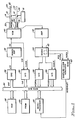
- a pair of disks 10, 12 are supported on a spindle 14 of a disk file drive motor 16.
- Each of the disks 10, 12 has two surfaces 20, 22 and 24, 26, respectively.
- surface 20 on disk 10 and surfaces 24, 26 on disk 12 are data recording surfaces.
- Surface 22 on disk 10 is a dedicated servo surface and contains only prerecorded servo information.
- the servo information on disk 10 is recorded in concentric tracks, with the position information typically written in such a manner that the intersections of adjacent servo tracks on servo surface 22 are radially aligned with the centerlines of the data tracks on surfaces 20, 24, and 26.
- the specific tracks on the data disks and the servo disk are accessed by heads 30, 32, 34, 36, each of which is associated with a respective disk surface and supported by an associated arm assembly.
- the heads 30, 32, 34, 36 are attached to a common accessing means or actuator, such as VCM 40.
- VCM 40 a common accessing means or actuator
- the signal read by servo head 32 is input to amplifier 42 and then demodulator 44. While the invention may be applied to operate with any of numerous types of servo patterns and servo signal demodulation techniques, the servo control system described herein utilizes a quadrature servo pattern, as described in the '103 patent and in IBM Technical Disclosure Bulletin , Vol. 21, No. 2 (July, 1978) pp. 804-805.
- the servo position information in the quadrature pattern on servo surface 22 is demodulated by demodulator 44 to generate two separate analog waveforms, designated primary (PESP) and quadrature (PESQ), as shown in Fig. 1.
- PESP primary
- PESQ quadrature
- the analog PESP and PESQ signals from demodulator 44 are sent to analog-to-digital (A/D) converters 88, 89, respectively.
- A/D analog-to-digital
- the discrete values of PESP and PESQ at any sample time are designated PESP(n) and PESQ(n), where n represents a time index for each digital sample.
- a microprocessor 80 is connected by data bus 84 and suitable address bus (not shown) to suitable memory devices, such as read/write memory (RAM) 82 and programmable read only memory (PROM) 83.
- Microprocessor 80 utilizes a control signal algorithm, as described in the '103 patent, to generate a control signal u(n).
- the control signal u(n) is output to digital-to-analog converter (DAC) 92 and amplified by power amplifier 98 to generate an analog current i(t) to VCM 40.
- DAC digital-to-analog converter
- A/D converter 90 analog-to-digital converter 90, which provides a digital current signal i(n) to microprocessor 80.
- Microprocessor 80 thus receives as inputs, at discrete sample times, the digital actuator current i(n) and the digital head position error signals PESP(n) and PESQ(n). Microprocessor 80 computes the actual position error signal PES(n) from the values of PESP(n) and PESQ(n), using conventional logic, as described in the '103 patent.
- demodulator 44 demodulates the position information in the quadrature servo pattern to generate analog PESP and PESQ signals.
- Demodulator 44 also contains synchronization detection circuitry 45 which receives timing information from synchronization areas in the quadrature servo pattern and outputs a PES clock signal.
- the PES clock signal is output by synchronization detection circuitry 45 at a frequency corresponding to the rate at which the synchronization areas in the quadrature servo pattern pass beneath the servo head 32.
- the PES clock signal synchronization detection circuitry 45 is input to a sampling clock generator 65 which provides an interrupt signal to microprocessor 80.
- Sampling clock generator 65 may be a digital counter which divides the PES clock frequency by a fixed value to provide an interrupt signal to microprocessor 80 at a frequency substantially less than the PES clock input frequency. Each interrupt signal to microprocessor 80 initiates the beginning of the control signal algorithm, which results in the output of control signal u(n).
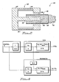
- VCM 40 comprises generally a movable portion 49 and a magnet structure 52.
- Movable portion 49 of the VCM includes a coil 50 which is wound on a coil support 53 and a bearing assembly (not shown) which rides on fixed guide rails (not shown) so as to provide linear movement of the heads across the disk surfaces.
- the heads 30, 32, 34, 36 (Fig. 1) and their associated arm assembly 70 are attached to coil support 53.
- Magnet structure 52 includes permanent magnets 54, 55, a center pole 56, and an outer support 57 which provides a magnetic flux return path.
- the coil is accelerated by a force generated when electrical current in the coil 50 occurs in the presence of magnetic flux in the gap 58 between the coil 50 and the magnet structure 52.
- the VCM force factor is then given as follows: The acceleration factor is then K f /M, where M is the mass of the movable portion 49 of VCM 40 and the attached head/arm assembly.
- the value of the acceleration factor K f /M must be known in order to accurately generate the control signal in disk files with conventional servo control systems, as well as in disk files with digital servo control systems which utilize a state estimator algorithm, such as that described in EP-A- 0243821.
- the acceleration factor is also important to compute an estimate of head position, velocity and acceleration.
- the state estimator algorithm requires the use of estimator constants, which are defined below.
- K p power amplifier gain
- T PES sampling time
- D computation time delay between input of analog PES and output of digital control signal
- m T - D.
- the p ij , g ij terms are generally invariable since they are functions of physical parameters of the disk file which do not generally change.
- the acceleration factor (K f /M) is not constant, but varies both with respect to a nominal value because of machine-to-machine variations in force factor K f and mass M, and with respect to head position because of variations in K f with head position.
- the performance of the servo control system will be less than optimal if the actual K f /M is different than the nominal K f /M to which the system was designed.
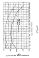
- the dashed line in Fig. 3 is a representation of the nominal acceleration factor as a function of head position, with position given in units of tracks. This relationship is determined experimentally by testing samples of disk files or by computation, based upon known values of the VCM parameters.
- the solid line in Fig. 3 is a representation of the actual acceleration factor as a function of head position for a specific disk file.
- the relationship of acceleration factor with head position has the same general shape for both the nominal VCM and the actual VCM. However, the two curves are displaced by an amount equal to the difference between the nominal acceleration factor and the actual acceleration factor. This difference is essentially a constant value, regardless of head position.
- a nominal acceleration factor (K f /M) NOM is selected to be the acceleration factor at approximately the mid-band of data tracks, which is a range over which there is minimal variation in force factor with head position.
- This value of the nominal acceleration factor is stored in PROM 83 and is the same value for all disk files.
- the value of (K f /M) NOM stored in PROM 83 is the average nominal acceleration factor between tracks 400 and 1200, and is a value of approximately 0.985 in arbitrary units.
- the computation for the measurement of the actual acceleration factor (K f /M) MES occurs every time the disk file servo control system is initialized, which is referred to as a "re-zero".
- a re-zero occurs every time the disk file is first powered-on and at other times on selection by the user.
- a forward seek is performed between tracks 400 and 1200.
- the value of VCM current less that component due to bias forces, is summed for each control signal calculation and this sum is stored in RAM 82.
- the equivalent current due to bias forces is referred to as “w e " and is provided by the state estimator, in the manner described in the '103 patent.)
- the estimated velocity is also stored in RAM 82.
- v(Q) is the terminal velocity and is equal to the integration of head acceleration over the time of the seek, where the units of integration are "samples," each sample being equal to the PES sampling time, T s .
- a(k) (K f /M) * i s (k). Since T s is constant and K f /M is assumed to be constant over the mid-band range of tracks, then which results in the above equation for (K f /M) MES .
- the term v(Q) is available from the state estimator during the Q-th sample.
- the actual velocity is also available in conventional disk files which use an electronic or mechanical tachometer to measure head velocity.
- a seek is also performed in the reverse direction and (K f /M) MES is calculated. The two values are then averaged to generate the actual (K f /M) MES which is used to compensate for the nominal (K f /M) NOM stored in PROM 83.
- K f /M The computed (K f /M) MES is then used to arrive at the actual K f /M as a function of head position, x, in the following manner.
- This polynomial is a curve fit of actual measured data for a nominal VCM. After these measurements have been made for a nominal VCM, the polynomial coefficients A, B and C are stored in PROM 83. These coefficients are identical for each disk file.
- the actual K f /M for each head position is calculated from the polynomial coefficients, the head position x, and the ratio of measured to actual acceleration factor at the mid-band (K f /M) MES /(K f /M) NOM .
- K f /M the ratio of measured to actual acceleration factor at the mid-band
- Fig. 3 since the functions for the nominal acceleration factor (dashed line) and the actual acceleration factor (solid line) are the same shape, the two functions can be related merely by a change to the coefficient C.
- (K f /M)(x) Ax2 + Bx + C * (K f /M) MES /(K f /M) NOM .
- the head position x is available to microprocessor 80 either as a result of the use of the state estimator algorithm, or from the demodulation of the PES to generate track crossing pulses, as is common in prior art disk files.
- the values of A, B and C are recalled from PROM 83 and the term (K f /M) MES /(K f /M) NOM recalled from RAM 82.
- Microprocessor 80 calculates K f /M, which is used as part of the control signal calculation.
- the manner in which the control signal is modified in a digital servo control system with a state estimator is illustrated in Fig. 4.
- the H(x) block is (K f /M)(x)/(K f /M) NOM and represents the acceleration factor variations in the VCM under control.
- the h(x) block is also (K f /M)(x)/(K f /M) NOM and represents the modification to the control signal which will force the VCM inputs (head position "x", velocity "v”, and acceleration "a") to the estimator to more closely represent the inputs from a nominal VCM.
- the unmodified control signal "u" is an input to the estimator.
- the h(x) block in the estimator operates on the output from the power amplifier to compensate for the h(x) modification to the control signal.
- the state estimator functions as a nominal state estimator, without any modifications to the estimator constants g ij and p ij .
- the control signal is modified with h(x) to force the VCM to behave as a nominal VCM with a fixed constant value of K f /M.
- this is not the preferred approach because modification of the estimator constants will change the transfer function of the system, and thus the performance of the VCM, from the nominal design.
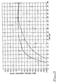
- the improved performance of the servo control system is depicted in Fig. 5.
- the dashed line represents the arrival of the head to the target track for a full stroke seek for a disk file in which the actual K f /M is approximately 6% below the nominal K f and in which a constant nominal value of K f /M is used during the computation of the control signal.
- the solid line represents the arrival of the head to the target track for a full stroke seek for a disk file with a 6% low K f /M but in which the actual K f /M has been calculated in the above described manner for each cycle of the control signal algorithm during the full stroke seek.
- the head arrives to the centerline of the target track approximately 0.8 milliseconds earlier than it would have if a constant nominal value of K f /M were used in the computation of the control signal.
Landscapes
- Moving Of Head For Track Selection And Changing (AREA)
- Moving Of The Head To Find And Align With The Track (AREA)
Applications Claiming Priority (2)
| Application Number | Priority Date | Filing Date | Title |
|---|---|---|---|
| US07/097,778 US4835633A (en) | 1987-09-16 | 1987-09-16 | Disk file digital servo control system with compensation for variation in actuator acceleration factor |
| US97778 | 1987-09-16 |
Publications (3)
| Publication Number | Publication Date |
|---|---|
| EP0308069A2 true EP0308069A2 (de) | 1989-03-22 |
| EP0308069A3 EP0308069A3 (de) | 1990-09-26 |
| EP0308069B1 EP0308069B1 (de) | 1996-11-06 |
Family
ID=22265082
Family Applications (1)
| Application Number | Title | Priority Date | Filing Date |
|---|---|---|---|
| EP88307582A Expired - Lifetime EP0308069B1 (de) | 1987-09-16 | 1988-08-16 | Plattendatei zur Aufnahme von Daten mit digitaler Servosteuerung |
Country Status (4)
| Country | Link |
|---|---|
| US (1) | US4835633A (de) |
| EP (1) | EP0308069B1 (de) |
| JP (1) | JPH071610B2 (de) |
| DE (1) | DE3855647T2 (de) |
Cited By (3)
| Publication number | Priority date | Publication date | Assignee | Title |
|---|---|---|---|---|
| EP0442650A3 (en) * | 1990-02-13 | 1992-09-09 | International Business Machines Corporation | Disk file with adaptive correction for nonrepeatable disk runout |
| WO1996019804A1 (en) * | 1994-12-19 | 1996-06-27 | Seagate Technology, Inc. | A system and method for controlling a seek operation in a disk drive |
| SG101476A1 (en) * | 2000-09-21 | 2004-01-30 | Toshiba Kk | Servo system with runout compensation for disk drive |
Families Citing this family (32)
| Publication number | Priority date | Publication date | Assignee | Title |
|---|---|---|---|---|
| US4982298A (en) * | 1988-08-01 | 1991-01-01 | Rigidyne Corporation | Adaptive velocity profile system for a disk drive head |
| US5132855A (en) * | 1989-11-28 | 1992-07-21 | Seagate Technology, Inc. | Adaptive velocity profile selection based on torque constant measurement |
| US5189571A (en) * | 1990-04-30 | 1993-02-23 | Seagate Technology, Inc. | Adaptive settle time minimization for a hard disk drive |
| US5128813A (en) * | 1990-06-21 | 1992-07-07 | Quantum Corporation | Thermal compensated head positioner servo for disk drive |
| ATE175801T1 (de) * | 1990-09-18 | 1999-01-15 | Rodime Plc | Digitale servosteuerung für ein plattenlaufwerk |
| US5329409A (en) * | 1991-07-24 | 1994-07-12 | Seagate Technology, Inc. | Correction of current feedback offset for disc drive servo systems |
| JPH05209263A (ja) * | 1992-01-13 | 1993-08-20 | Nec Corp | スパッタ合金膜の製造方法及びその装置 |
| JP2608223B2 (ja) * | 1992-03-19 | 1997-05-07 | 富士通株式会社 | アクチュエータのトルク補正方法 |
| US5510939A (en) * | 1992-07-16 | 1996-04-23 | Micropolis Corporation | Disk drive with adaptive positioning |
| US5576910A (en) * | 1993-06-04 | 1996-11-19 | Cirrus Logic, Inc. | Burst comparison and sequential technique for determining servo control in a mass storage disk device |
| US5477103A (en) * | 1993-06-04 | 1995-12-19 | Cirrus Logic, Inc. | Sequence, timing and synchronization technique for servo system controller of a computer disk mass storage device |
| US5384524A (en) * | 1993-09-02 | 1995-01-24 | Cirrus Logic, Inc. | Voice coil motor control circuit and method for servo system control in a computer mass storage device |
| KR0128040B1 (ko) | 1993-11-27 | 1998-04-04 | 김광호 | 디스크 기록 매체를 이용하는 데이타 저장장치의 디지탈 서보제어장치 및 방법 |
| US6115205A (en) * | 1994-03-11 | 2000-09-05 | Seagate Technology, Inc. | Method for adapting seeks of a disc drive transducer to the maximum actuator current available to accelerate and decelerate the transducer |
| US5473550A (en) * | 1994-03-21 | 1995-12-05 | Seagate Technology, Inc. | Fast calibration using microsteps |
| JP3829994B2 (ja) * | 1995-01-06 | 2006-10-04 | 富士通株式会社 | ファイル装置の開発装置及び開発システム |
| KR0162607B1 (ko) * | 1995-12-20 | 1999-01-15 | 김광호 | 보이스코일모터 구동 제어회로 |
| US5912782A (en) * | 1996-03-27 | 1999-06-15 | International Business Machines Corporation | System and method for adjusting actuator control current for directional torque variance in a disk drive |
| US5825579A (en) * | 1996-04-04 | 1998-10-20 | International Business Machines Corporation | Disk drive servo sensing gain normalization and linearization |
| US6163430A (en) * | 1996-07-18 | 2000-12-19 | Seagate Technology Llc | Disc drive positioning system with variable deceleration curve |
| JP3588519B2 (ja) * | 1996-08-19 | 2004-11-10 | 富士通株式会社 | 光学的記憶装置 |
| US5898286A (en) * | 1997-01-13 | 1999-04-27 | International Business Machines Corporation | Digital servo control system for a data recording disk file with improved saturation modelling |
| US6490120B1 (en) | 1997-08-29 | 2002-12-03 | Seagate Technology Llc | Servo gain optimization using a variable convergence factor |
| US6614617B1 (en) * | 1998-05-18 | 2003-09-02 | Seagate Technology Llc | Voice coil motor force constant calibration method and apparatus |
| US6342985B1 (en) | 1998-09-15 | 2002-01-29 | International Business Machines Corporation | Method and apparatus for improving disk drive seek performance |
| US6590735B1 (en) * | 1999-04-21 | 2003-07-08 | Seagate Technology Llc | Continuously adaptive seek deceleration profiling |
| US6594105B1 (en) | 1999-04-21 | 2003-07-15 | Seagate Technology Llc | Time optimal seeks using linear velocity scheduling |
| US6690533B2 (en) | 2000-02-24 | 2004-02-10 | Seagate Technology Llc | Drive level actuator imbalance torque test |
| US6674606B1 (en) * | 2000-04-21 | 2004-01-06 | Seagate Technology Llc | Method and apparatus to normalize the acceleration constant |
| US6930851B2 (en) * | 2003-06-26 | 2005-08-16 | Seagate Technology Llc | Guiding a sensor using a broadly-curved lateral profile |
| US7549407B2 (en) | 2007-03-28 | 2009-06-23 | Gm Global Technology Operations, Inc. | Method and system for controlling a valve device |
| US11676629B1 (en) * | 2022-01-14 | 2023-06-13 | Western Digital Technologies, Inc. | Sampled-data polydyne feedforward position control |
Family Cites Families (6)
| Publication number | Priority date | Publication date | Assignee | Title |
|---|---|---|---|---|
| US4133011A (en) * | 1977-12-23 | 1979-01-02 | International Business Machines Corporation | Sampled data positioning system employing a model of the physical system for time optimal control |
| JPS60113369A (ja) * | 1983-11-22 | 1985-06-19 | Nec Corp | 磁気ヘツドの位置決め回路 |
| FR2594586B1 (fr) * | 1986-02-14 | 1988-04-29 | Bull Sa | Procede pour deplacer un systeme mobile par rapport a un support d'informations et dispositif pour le mettre en oeuvre |
| US4679103A (en) * | 1986-04-29 | 1987-07-07 | International Business Machines Corporation | Digital servo control system for a data recording disk file |
| US4697127A (en) * | 1986-06-09 | 1987-09-29 | International Business Machines Corporation | Adaptive control technique for a dynamic system |
| JPS63274395A (ja) * | 1987-04-30 | 1988-11-11 | Fujitsu Ltd | 磁気ヘッド位置決め制御方式 |
-
1987
- 1987-09-16 US US07/097,778 patent/US4835633A/en not_active Expired - Lifetime
-
1988
- 1988-08-12 JP JP63200307A patent/JPH071610B2/ja not_active Expired - Lifetime
- 1988-08-16 EP EP88307582A patent/EP0308069B1/de not_active Expired - Lifetime
- 1988-08-16 DE DE3855647T patent/DE3855647T2/de not_active Expired - Fee Related
Cited By (4)
| Publication number | Priority date | Publication date | Assignee | Title |
|---|---|---|---|---|
| EP0442650A3 (en) * | 1990-02-13 | 1992-09-09 | International Business Machines Corporation | Disk file with adaptive correction for nonrepeatable disk runout |
| WO1996019804A1 (en) * | 1994-12-19 | 1996-06-27 | Seagate Technology, Inc. | A system and method for controlling a seek operation in a disk drive |
| SG101476A1 (en) * | 2000-09-21 | 2004-01-30 | Toshiba Kk | Servo system with runout compensation for disk drive |
| US6760183B2 (en) | 2000-09-21 | 2004-07-06 | Kabushiki Kaisha Toshiba | Servo system with runout compensation for disk drive |
Also Published As
| Publication number | Publication date |
|---|---|
| US4835633A (en) | 1989-05-30 |
| DE3855647T2 (de) | 1997-05-07 |
| EP0308069A3 (de) | 1990-09-26 |
| JPS6476471A (en) | 1989-03-22 |
| JPH071610B2 (ja) | 1995-01-11 |
| DE3855647D1 (de) | 1996-12-12 |
| EP0308069B1 (de) | 1996-11-06 |
Similar Documents
| Publication | Publication Date | Title |
|---|---|---|
| US4835633A (en) | Disk file digital servo control system with compensation for variation in actuator acceleration factor | |
| EP0243821B1 (de) | Steuerungssystem für scheibenförmigen Aufzeichnungsträger | |
| EP0003070B1 (de) | Zeitoptimale digitale Steuerung zum Positionieren unter Verwendung eines Modells der Vorrichtung | |
| US4816941A (en) | Disk file digital servo control system with optimized sampling rate | |
| EP0442650B1 (de) | Plattenspeicher mit adaptiver Korrektur des nichtwiederholenden Rundlauffehlers der Platte | |
| EP0414694B1 (de) | Abschätzung-positionierungssystem und verfahren | |
| EP0361786B1 (de) | Digitale Servosteuerung für Plattenspeicher | |
| US5576909A (en) | Method for positioning a data transducer head in a rotating disk drive data storage device | |
| US5917672A (en) | Disk file head positioning servo system incorporating adaptive saturated seek and head offset compensation | |
| EP0209692B1 (de) | Servoregelungssystem für eine Magnetplattenvorrichtung mit schneller Verminderung des mehrmaligen Kopfpositionsfehlers | |
| US6850385B1 (en) | Repeated servo runout error compensation in a disc drive | |
| US5473550A (en) | Fast calibration using microsteps | |
| US4792870A (en) | Method and apparatus for track accessing using a predicted state vector | |
| EP0308070B1 (de) | Datenaufzeichnungs-Plattendatei mit digitaler Nachlaufregelung | |
| US5835300A (en) | Dynamic compensation of servo burst measurement offsets in a disc drive | |
| US6545838B1 (en) | Self tuning model reference controller in a disc drive | |
| US5774297A (en) | Dynamic compensation of servo burst measurement offsets in a disc drive | |
| EP0456348A2 (de) | Methode und Gerät zur Kopfpositionssteuerung in Plattenspeichergerät | |
| JPH04285774A (ja) | アクセス制御装置 | |
| JPS61145613A (ja) | サ−ボモ−タ制御方式 | |
| JPH0330157A (ja) | 磁気デイスク装置の位置制御装置 | |
| EP0791924A2 (de) | Verfahren und Gerät zum Reduzieren der Phasenverzögerung die aus der Digital-Analogwandlung resultiert | |
| JPH05282634A (ja) | 磁気ディスク駆動装置 | |
| JPH05282811A (ja) | 磁気ディスク駆動装置 | |
| JPH0330155A (ja) | 磁気デイスク装置の位置制御装置 |
Legal Events
| Date | Code | Title | Description |
|---|---|---|---|
| PUAI | Public reference made under article 153(3) epc to a published international application that has entered the european phase |
Free format text: ORIGINAL CODE: 0009012 |
|
| AK | Designated contracting states |
Kind code of ref document: A2 Designated state(s): DE FR GB |
|
| 17P | Request for examination filed |
Effective date: 19890720 |
|
| PUAL | Search report despatched |
Free format text: ORIGINAL CODE: 0009013 |
|
| AK | Designated contracting states |
Kind code of ref document: A3 Designated state(s): DE FR GB |
|
| 17Q | First examination report despatched |
Effective date: 19920421 |
|
| GRAG | Despatch of communication of intention to grant |
Free format text: ORIGINAL CODE: EPIDOS AGRA |
|
| GRAH | Despatch of communication of intention to grant a patent |
Free format text: ORIGINAL CODE: EPIDOS IGRA |
|
| GRAH | Despatch of communication of intention to grant a patent |
Free format text: ORIGINAL CODE: EPIDOS IGRA |
|
| GRAA | (expected) grant |
Free format text: ORIGINAL CODE: 0009210 |
|
| AK | Designated contracting states |
Kind code of ref document: B1 Designated state(s): DE FR GB |
|
| REF | Corresponds to: |
Ref document number: 3855647 Country of ref document: DE Date of ref document: 19961212 |
|
| ET | Fr: translation filed | ||
| PLBE | No opposition filed within time limit |
Free format text: ORIGINAL CODE: 0009261 |
|
| STAA | Information on the status of an ep patent application or granted ep patent |
Free format text: STATUS: NO OPPOSITION FILED WITHIN TIME LIMIT |
|
| 26N | No opposition filed | ||
| PG25 | Lapsed in a contracting state [announced via postgrant information from national office to epo] |
Ref country code: FR Free format text: LAPSE BECAUSE OF NON-PAYMENT OF DUE FEES Effective date: 19980430 |
|
| REG | Reference to a national code |
Ref country code: FR Ref legal event code: ST |
|
| PGFP | Annual fee paid to national office [announced via postgrant information from national office to epo] |
Ref country code: DE Payment date: 19990816 Year of fee payment: 12 |
|
| PG25 | Lapsed in a contracting state [announced via postgrant information from national office to epo] |
Ref country code: DE Free format text: LAPSE BECAUSE OF NON-PAYMENT OF DUE FEES Effective date: 20010501 |
|
| REG | Reference to a national code |
Ref country code: GB Ref legal event code: IF02 |
|
| REG | Reference to a national code |
Ref country code: GB Ref legal event code: 732E |
|
| PGFP | Annual fee paid to national office [announced via postgrant information from national office to epo] |
Ref country code: GB Payment date: 20070716 Year of fee payment: 20 |
|
| REG | Reference to a national code |
Ref country code: GB Ref legal event code: PE20 Expiry date: 20080815 |
|
| PG25 | Lapsed in a contracting state [announced via postgrant information from national office to epo] |
Ref country code: GB Free format text: LAPSE BECAUSE OF EXPIRATION OF PROTECTION Effective date: 20080815 |