EP0442498B1 - Steuereinrichtung für die Dauer der Ladungssammlung - Google Patents
Steuereinrichtung für die Dauer der Ladungssammlung Download PDFInfo
- Publication number
- EP0442498B1 EP0442498B1 EP91102103A EP91102103A EP0442498B1 EP 0442498 B1 EP0442498 B1 EP 0442498B1 EP 91102103 A EP91102103 A EP 91102103A EP 91102103 A EP91102103 A EP 91102103A EP 0442498 B1 EP0442498 B1 EP 0442498B1
- Authority
- EP
- European Patent Office
- Prior art keywords
- sab
- saa
- viw
- sensor means
- accumulation
- Prior art date
- Legal status (The legal status is an assumption and is not a legal conclusion. Google has not performed a legal analysis and makes no representation as to the accuracy of the status listed.)
- Expired - Lifetime
Links
- 238000009825 accumulation Methods 0.000 title claims description 115
- 230000000007 visual effect Effects 0.000 claims description 62
- 230000003287 optical effect Effects 0.000 claims description 27
- 238000000034 method Methods 0.000 description 24
- 238000010586 diagram Methods 0.000 description 9
- 238000003491 array Methods 0.000 description 8
- 238000010276 construction Methods 0.000 description 8
- KAWDSEAQDBNLOH-UHFFFAOYSA-M sodium 6'-hydroxy-5-[2-[4-(3-hydroxy-2-methylimidazo[1,2-a]pyrazin-6-yl)phenoxy]ethylcarbamothioylamino]-3-oxospiro[2-benzofuran-1,9'-xanthene]-3'-olate Chemical compound [Na+].Cc1nc2cnc(cn2c1O)-c1ccc(OCCNC(=S)Nc2ccc3c(c2)C(=O)OC32c3ccc(O)cc3Oc3cc([O-])ccc23)cc1 KAWDSEAQDBNLOH-UHFFFAOYSA-M 0.000 description 8
- 238000001514 detection method Methods 0.000 description 7
- 238000004364 calculation method Methods 0.000 description 5
- 230000004907 flux Effects 0.000 description 5
- 238000005259 measurement Methods 0.000 description 5
- 230000004044 response Effects 0.000 description 4
- 238000012546 transfer Methods 0.000 description 4
- 238000012790 confirmation Methods 0.000 description 3
- 238000009826 distribution Methods 0.000 description 3
- 238000012545 processing Methods 0.000 description 3
- 210000001747 pupil Anatomy 0.000 description 3
- 238000002407 reforming Methods 0.000 description 3
- 238000006243 chemical reaction Methods 0.000 description 2
- 238000007796 conventional method Methods 0.000 description 2
- 230000000694 effects Effects 0.000 description 2
- 238000002474 experimental method Methods 0.000 description 2
- 230000003213 activating effect Effects 0.000 description 1
- 238000004891 communication Methods 0.000 description 1
- 238000012937 correction Methods 0.000 description 1
- 230000007423 decrease Effects 0.000 description 1
- 239000004744 fabric Substances 0.000 description 1
- 230000010354 integration Effects 0.000 description 1
- 239000004973 liquid crystal related substance Substances 0.000 description 1
- 238000012986 modification Methods 0.000 description 1
- 230000004048 modification Effects 0.000 description 1
- 238000012544 monitoring process Methods 0.000 description 1
- 238000003672 processing method Methods 0.000 description 1
- 230000011514 reflex Effects 0.000 description 1
- 238000004904 shortening Methods 0.000 description 1
- 230000008054 signal transmission Effects 0.000 description 1
- 239000007787 solid Substances 0.000 description 1
Images


Classifications
-
- G—PHYSICS
- G02—OPTICS
- G02B—OPTICAL ELEMENTS, SYSTEMS OR APPARATUS
- G02B7/00—Mountings, adjusting means, or light-tight connections, for optical elements
- G02B7/28—Systems for automatic generation of focusing signals
- G02B7/34—Systems for automatic generation of focusing signals using different areas in a pupil plane
- G02B7/346—Systems for automatic generation of focusing signals using different areas in a pupil plane using horizontal and vertical areas in the pupil plane, i.e. wide area autofocusing
-
- C—CHEMISTRY; METALLURGY
- C08—ORGANIC MACROMOLECULAR COMPOUNDS; THEIR PREPARATION OR CHEMICAL WORKING-UP; COMPOSITIONS BASED THEREON
- C08F—MACROMOLECULAR COMPOUNDS OBTAINED BY REACTIONS ONLY INVOLVING CARBON-TO-CARBON UNSATURATED BONDS
- C08F210/00—Copolymers of unsaturated aliphatic hydrocarbons having only one carbon-to-carbon double bond
- C08F210/04—Monomers containing three or four carbon atoms
- C08F210/06—Propene
-
- C—CHEMISTRY; METALLURGY
- C08—ORGANIC MACROMOLECULAR COMPOUNDS; THEIR PREPARATION OR CHEMICAL WORKING-UP; COMPOSITIONS BASED THEREON
- C08F—MACROMOLECULAR COMPOUNDS OBTAINED BY REACTIONS ONLY INVOLVING CARBON-TO-CARBON UNSATURATED BONDS
- C08F210/00—Copolymers of unsaturated aliphatic hydrocarbons having only one carbon-to-carbon double bond
- C08F210/04—Monomers containing three or four carbon atoms
- C08F210/08—Butenes
Definitions
- the present invention relates to an accumulation time control apparatus of sensors which are used in a focal point detecting apparatus having a plurality of distance measuring visual fields or the like and an image pick-up apparatus.
- Fig. 1 shows an AF optical system of the typical double image phase difference detecting type.
- a field lens FLD having the same optical axis as that of a photographing lens LNS whose focal point is to be detected is provided.
- Two secondary image forming lenses FCLA and FCLB are arranged at positions which are symmetrical with respect to an optical axis behind the field lens FLD.
- Sensor trains SAA and SAB are arranged at positions further behind the secondary image forming lenses FCLA and FCLB.
- Diaphragms DIA and DIB are arranged near the secondary image forming lenses FCLA and FCLB.
- the field lens FLD forms an image of an exit pupil of the photographing lens LNS almost onto pupil surfaces of the two secondary image forming lenses FCLA and FCLB.
- the light fluxes which respectively enter the secondary image forming lenses FCLA and FCLB are light fluxes which were emitted from regions having the same area which are not mutually overlapped and correspond to the secondary image forming lenses FCLA and FCLB on the exit pupil surface of the photographing lens LNS.
- Fig. 2 shows an example of photoelectric conversion outputs of two images formed on the sensor trains SAA and SAB.
- the output of the sensor train SAA assumes A(i) and the output of the sensor train SAB assumes B(i).
- As the number of pixels of each sensor train or array at least five pixels are needed and, preferably, tens or more pixels are necessary.
- the photographing lens LNS can be set into an in-focus state by adjusting a focal point of the photographing lens LNS on the basis of the image deviation amount obtained by the methods disclosed in those Official Gazettes.
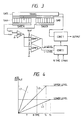
- control sensors SAGCA and SAGCB are arranged at positions adjacent to the sensor arrays SAA and SAB and observe almost the same object portion as the distance measuring visual field images. Outputs of the control sensors SAGCA and SAGCB are added by an adder ADD and an addition signal is supplied from the adder ADD to comparators COMP 1 and COMP 2 .
- a referred potential which is compared with the addition output by each comparator is obtained by dividing a reference potential V ref .
- the referred potentials correspond respectively to the upper level and lower level in Fig. 4.
- Output signals of the comparators are always supplied to a control circuit CONT 2 and are referred at a necessary time point.
- a control signal to control a control circuit CONT 1 is generated from the control circuit CONT 2 .
- the control circuit CONT 1 receives the control signal from the control circuit CONT 2 and transfers and reads out the photo charges of the AF sensors SAA and SAB to a transfer channel TRANS through a gate GATE in order to terminate the accumulation of the charges by the AF sensors SAA and SAB.
- the read-out charges are supplied to an operating circuit through an amplifier of a designated gain.
- the control circuit CONT 2 receives two kinds of time designation pulses BTIME and TMAX and executes the following operation.
- the accumulation is finished at that time point and a signal is generated so as to select an amplifier of a low gain in the control circuit CONT 1 .
- the output signal of the adder ADD changes in accordance with a straight line L 1 in Fig 4 with the elapse of the accumulation time and the accumulation is finished at time T 1 before the time point of the pulse BTIME.
- the gain of the amplifier in the control circuit CONT 1 is selected in response to the pulse BTIME. That is, if the accumulation amount of the control sensor SAGCA, SAGCB is higher than the lower level at that time point, the low gain is selected and the accumulation is continued until the accumulation amount is equal to the upper level of the comparator.
- the output of the adder ADD changes in accordance with the straight line L 2 in Fig. 4. The accumulation is finished at time T 2 .
- the control circuit CONT 2 instructs the control circuit CONT 1 to use an amplifier of a high gain.
- a ratio of two gains is set to a value which is equal to a ratio of two comparison levels.
- an automatic focusing apparatus of a camera which comprises focus detecting means for detecting repeatedly focus conditions of a photographic lens and outputs successively focus signals corresponding to the focus conditions.
- the focus detecting means comprises a multiple point focus detection module having CCD image sensor arrays (16a, 16b, 16c), wherein each CCD image sensor array includes a light receiving portion, an accumulating portion and a transfer portion.
- a monitoring light receiving element (MA) for controlling an integration period for the accumulation portion of the CCD is provided on one of the lateral longitudinal sides of a basic region of a central island (IS2), which island is one of three areas wherein focus detection can be effected. Further, as can be seen from Figs.
- the CCD image sensor arrays have a long photosensitive surface and are arranged in a predetermined direction in correspondence to a respective distance measuring field. Moreover, the direction of the distance measuring field of at least one of the CCD image sensor means (IS2) crosses the direction of the distance measuring field of any of the others of the CCD image sensor means (IS1, IS3). Furthermore, drive means are provided for driving the photographic lens for focus adjustment and predicting means for predicting an in-focus point from the plurality of focus signals from the focus detecting means.
- this apparatus includes control means for controlling the drive means to drive the photographic lens toward the in-focus point predicted by the predicting means, size detecting means for detecting a size of an object, forbidding means for forbidding the control of drive by the control means and further control means for controlling operation of the forbidding means based on the size of the object detected by the size detecting means.
- the apparatus has an object distance measuring means for measuring an object distance from the camera to the object, wherein the size detecting means determines the size of the object based on the measured object distance.
- document US-A-4 635 126 discloses an image pick-up system in which the accumulation time of accumulation type image pick-up elements and the gain of an amplifier for amplifying the output of the pick-up elements are controlled through an accumulation time and gain control device on the basis of the brightness of the image light received by the pick-up elements.
- the gain of an amplifier is varied in order to prevent the lengthening of the accumulation time in case of low brightness conditions.
- the accumulation type image pick-up element consists of a photosensitive portion including an arrangement along a number of columns and rows of photosensitive cells.
- a horizontal transfer register for transferring stored charges of the CCD of a memory portion line by line and an output amplifier for converting the charges transferred from the register into a voltage.
- an accumulation time and gain control circuit for controlling on the basis of brightness information the gain of a variable gain amplifying circuit which amplifies the signal accumulation time of the image pick-up element and the output of the image pick-up element.
- the accumulation time and the gain are set to first predetermined values independent of a dark current level, whereas in case of a low brightness, the value of the gain is set to a second predetermined value and the accumulation time is set to a second or a third predetermined value depending on the dark current level.
- control device for a camera system
- the control device comprises a central processing unit for use in sequence control of the whole part of the camera, calculation and control of an exposure of the camera and an automatic focus control.
- An automatic focusing detection unit includes a CCD image sensor of one dimension self scan type and a CCD driving unit.
- the CCD image sensor produces an image signal of an analog form upon scanning the photographic object.
- the CPU controls the start of the accumulation time and is informed by the automatic focusing detection circuit when the amount of charges accumulated in the CCD reaches a predetermined level. The time interval for the charge accumulation varies with the brightness of the photographic object.
- the charge accumulation in the CCD is started at the same time of the starting the light measurement calculation and is finished at the latest after the end of the light measurement calculation, thus shortening the time interval required for judging the focus condition in comparison to the case where the charge accumulation is started after the end of the light measurement calculation.
- an in-focus state detecting apparatus for a single-lens reflex camera as shown in Fig. 6 has been proposed.
- the light flux for AF which was reflected downwardly by a submirror SUBM enters a visual field mask VMSK having three different distance measuring visual fields through field lenses FLD 1 , FLD 2 , and FLD 3 .
- the AF light fluxes are transmitted via mirror reflecting members M 1 and M 2 to extend a length of optical path and enter a pair of image reforming lenses FCLA and FCLB and images are again formed onto the surfaces of the AF sensors SAA 1 to SAA 3 , SAB 1 to SAB 3 .
- Three pairs of sensor arrays that is, a pair of sensor arrays SAA 1 and SAB 1 , a pair of sensor arrays SAA 2 and SAB 2 , and a pair of sensor arrays SAA 3 and SAB 3 are used to individually receive the reformed optical images which come from three visual fields of the visual field mask VMSK.
- a method of controlling the AF sensors is the same as that in the conventional apparatus.
- the accumulating operations of all of the AF sensor pairs are started in a lump and the accumulation control as mentioned above is executed for each AF sensor pair.
- the above method is based on the idea such that the main object exists at the nearest position and the images existing at relatively remote positions other than the main object are the background.
- a device wherein weighting is performed in a manner such that the selection algorithm of the distance measuring points is changed in accordance with a focal point distance of the photographing lens and on the side of a short focal point, the selection of the central visual field is made easy or the like.
- the AF sensor output of the distance measuring point at which a portion of a low luminance is seen does not reach a predetermined level, so that the accumulation is not finished, whereby a desired time of the AF operation becomes remarkably long, and the operability of the apparatus is lost.
- a contrast constant control method has been known as a method of controlling the accumulation time.
- contrasts of the light intensity distributions on the AF sensors differ depending on a pattern of an object, so that the accumulation times of the AF sensors having different distance measuring visual field differ.
- the AF sensor which observes a wall or a cloth of a solid color
- a contrast enough to reach a comparison level is not obtained. Therefore, even in a bright state, the maximum limit accumulating operation is soon performed.
- the invention is made in consideration of the above circumstances and it is an object of the invention to improve a response speed of an apparatus for controlling accumulation times for a plurality of sensor means as well as of an image pick-up apparatus.
- the whole accumulation time can be determined by the time which was required to first complete the accumulation. Therefore, for example, in the case of applying the invention to an AF apparatus, even in the case where either one of the distance measuring visual fields has extremely lower luminance and contrast than those of the other distance measuring visual fields, the delay of the AF operation by such a distance measuring visual field can be prevented. The response speed of such a kind of apparatus can be remarkably improved.
- the photo sensitive surface of at least one of the sensor means includes a photo sensitive surface which crosses the direction of the photo sensitive surfaces of the other sensor means, so that a dependency of the photo sensitive surface of the sensor means on the pattern can be reduced.
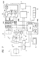
- FIG. 7 is a block diagram showing a construction of an image pick-up apparatus, i.e. an electronic still camera, according to an embodiment.
- an image pick-up light from an object which was supplied through an image pick-up optical system 1 is photoelectrically converted by an image pick-up device 2 using a CCD or the like.
- An electric video signal obtained by the photoelectric conversion is processed by a signal processing circuit 3. After that, the video signal is recorded on a recording medium such as a magnetic disk or the like by a recording section 4.
- the image pick-up optical system 1 has an iris 5 and a focusing lens 6.
- the iris 5 is driven by an iris driving circuit 7.
- the focusing lens 6 is driven by a focusing lens driving circuit 8.
- the image pick-up lights which were reflected by mirrors 9 and 10 arranged on an optical axis of the image pick-up optical system 1 are led to an AF optical system 11 and a photometric optical system 12, respectively.
- the image pick-up light which was led to the AF optical system 11 is illuminated onto an AF sensor SAS through various optical devices as shown in Fig. 6.
- the image pick-up light which was led to the photometric optical system 12 is illuminated onto a photometric sensor 13.
- the electronic still camera has: a control circuit CONT to control the AF sensor SAS; and a microprocessor PRS to control the control circuit CONT, the AF sensor SAS, and the like.
- a CPU which constructs the microprocessor PRS controls the signal processing circuit 3 and the recording section 4 in accordance with the operations of various operation switches 14. Further, the CPU supplies an iris control signal according to a photometric output of the photometric sensor 13 to the iris driving circuit 7.
- the CPU also supplies a focusing control signal according to an output of the AF sensor SAS, which is supplied through the control circuit CONT, to the focusing driving circuit 8.
- An operating mode and the like of the electronic still camera are displayed by a display device 15 using a liquid crystal or the like.
- the microprocessor PRS comprises a CPU, a ROM, and a RAM.
- the CPU properly reads out and executes various program data stored in the ROM in accordance with the operations of the switches and controls the writing and reading operations of the various data which are supplied in association with the execution of the program into and from the RAM.
- the AF sensor SAS has three pairs of sensors.
- the AF light fluxes are irradiated to a pair of sensors SAA 1 and SAB 1 , a pair of sensors SAA 2 and SAB 2 , and a pair of sensors SAA 3 and SAB 3 through field lenses FLD 1 to FLD 3 and a visual field mask VMSK of the AF image pick-up system shown in Fig. 6.
- Outputs of the sensors SAA 1 to SAA 3 , SAB 1 to SAB 3 are used as control outputs.
- the control outputs can be also derived from control sensors.
- the control circuit CONT comprises: analog amplifiers A 1 and A 2 to amplify the output of the sensor SAS by different predetermined gains, respectively; a switching circuit SW to selectively supply outputs of the analog amplifiers to an A/D converter; a gain control circuit G CONT to substantially switch the gains for the outputs of the analog amplifiers A 1 , A 2 by switching and controlling the switching circuit SW in accordance with an output level of the sensor SAS; and a timing control circuit T CONT to control the timings to start or stop the accumulation of the sensor SAS.
- control circuit CONT and the microprocessor in the embodiment can be also obviously constructed by a one-chip microcomputer.
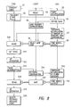
- Fig. 8 is a flowchart showing the operation of the first embodiment of the invention. The operation will now be described hereinbelow.
- the microprocessor PRS sends an accumulation start signal START to the AF sensor through a data communication path FTIME regarding the timings at the start of the AF sequence after the iris 5 was adjusted (step S1), thereby starting the accumulation of the AF sensor SAS (step S2).
- the microprocessor PRS also resets the control circuit CONT into the initial state (step S3).
- the microprocessor PRS supplies a pulse BTIME to the AF sensor SAS through the line FTIME for a gain decision time in accordance with the content of the program (step S4).
- each of the three sensor array pairs in the AF sensor SAS determines an accumulation termination level to either the upper level or the lower level on the basis of the foregoing method of Fig. 4 (step S5).
- the accumulation termination level (corresponding to the selected amplifier gain upon reading) of each sensor array pair is supplied through a line GAIN to the gain control circuit G CONT and stored (step S6).
- the AF sensor SAS communicates an ID signal of such a pair of sensor array whose accumulation was finished to the microprocessor PRS and the control circuit CONT through a line SLINE (step S7).
- the AF sensor SAS also time sequentially generates an image signal from a terminal SOUT in response to a clock signal (not shown) (step S8). Further, a proper one of the gains of the analog amplifiers A 1 and A 2 having different predetermined gains is selected on the basis of the designated gain stored in the gain control circuit G CONT (step S9).
- the output of the AF sensor SAS is amplified and A/D converted and sent as digital data to the microprocessor PRS.
- the microprocessor PRS reads a signal on the line SLINE before one AF focal point of the distance measuring visual field is calculated from the output signals of the sensor array pair SAA 1 and SAB 1 (step S10).
- one AF focal point of the distance measuring visual field is calculated on the basis of the output signals of the sensor array pair SAA 1 and SAB 1 (step S12). After that, the calculated AF focal point is stored.
- step S13 When the timer interruption is generated by the program timer (step S13), a program to forcedly terminate the accumulating operation of the other sensor array pair which is executing the accumulation even if a charge accumulation amount of such a sensor array pair does not reach the accumulation end level is activated (step S14).
- a forced end signal is sent to the line FTIME.
- the timing control circuit T CONT Upon reception of the forced end signal, the timing control circuit T CONT sends an accumulation end control signal TINT to the AF sensor SAS, thereby finishing the accumulating operation (step S15).
- step S20 If the accumulation level of the other line of the sensor array pair has reached a predetermined end level for a period of time between TINT 1 and T end , the termination of the accumulation, the signal transmission, the calculation of the AF focal point, and the like are executed in accordance with the ordinary control sequence (steps S16 to S19). After that, the optimum distance measuring point is selected from the AF operation outputs (step S20).
- the AF operation output at the distance measuring point is supplied to the focusing lens driving circuit 8 (AF circuit) and the focusing lens 6 (AF lens) is moved.
- the accumulation of the sensor array pair which is executing the accumulating operation is finished by the above requirement.
- the operating times of the sensors in the case where the luminance differences among the distance measuring points are large and there is a remarkably large variation among the accumulation times in the conventional method can be suppressed to a constant time (T end ).
- T end a constant time
- a magnification coefficient K is properly set to a value within a range of 1 ⁇ K ⁇ 8, preferably, 1 ⁇ K ⁇ 4. If the value of K is too large, an effect to reduce the accumulation time is not obtained. If it is too small, there is a tendency such that a priority is eventually given to a high luminance and a high contrast.
- the accumulating operations of the other sensor array pairs are finished at the time which is K times as long as the accumulation time TINT 1 of the sensor array pair whose accumulating operation was first finished.
- the accumulation is finished before charges are accumulated into the other sensor array pair in a visual field which is seeing a main object until a meaning signal level. Therefore, only when the input signal is a signal having a high reliability in which an in-focus state can be detected as a result of the discrimination, the accumulation time of such a sensor array pair is used as TINT 1 in the above equation (1). If a sufficient high speed microcomputer is used, the control delay time can be ignored because a time which is required for the operation and discrimination is short.
- the set lower limit value is set to a value within a range from 20 to 200 msec, preferably, about 40 to 160 msec. Since the accumulating operations of a few times are required until the photographing lens, i.e. the focusing lens 6, is set to an in-focus state, if the above lower limit value is set to a long time, the effect of the invention decreases.
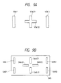
- Fig. 9A shows an arrangement of a distance measuring visual field of the AF system of the embodiment. That is, a lateral visual field VIW 22 of a distance measuring visual field of the central portion is added to the foregoing embodiment.
- the lateral visual field VIW 22 is used to improve a dependency on a pattern. If only a visual field in the vertical direction is used, the AF system cannot respond to a pattern such as a vertical line. Therefore, the lateral visual field VIW 22 which crosses perpendicularly to a visual field VIW 21 in the vertical direction is provided, thereby eliminating a merit and a demerit of an object depending on the direction of a pattern.
- an optical method of perpendicularly arranging the central visual fields VIW 21 and VIW 22 can be realized by arranging four image reforming lenses in a crossing (+) shape. It is sufficient to also provide two AF systems in each of which a pair of two image reforming lenses are provided and which have hitherto frequently been used. With the above construction, a sensor arrangement shown in Fig. 9B is derived. That is,
- the accumulation times of the above four sensor array pairs are controlled in the following manner.
- the value of K in the equation (1) is set to a small value within a range from 1 to 4, preferably, from 1 to 2, thereby controlling the accumulation.
- K is set to a value within a range from 1 to 8, preferably, from 2 to 4 in the equation (1) in a manner similar to that in the foregoing embodiment.
- the visual field which earlier finishes the accumulation has information suitable for the AF operation. Since such information relates to the same position of the object, it is advantageous for the system to also finish the accumulation of the array in the other perpendicular direction as quickly as possible in accordance with the operation of the AF sensor array pair of the better visual field which first finishes the accumulation.
- the value of K in the equation (1) is changed and applied between the two central visual fields VIW 21 and VIW 22 and among three points of the left, right, and center positions, and it is desirable to use a small value in the case of between the two central visual fields and to use a relatively large value similarly to the foregoing embodiment in the case among the three left, right, and center points.
- the accumulation is forcedly finished among the three right, left, and center points, if the sensor array pair which sees either one of the vertical and lateral visual fields in the central portion first finished the accumulation, the accumulating operations of the right and left sensors are limited on the basis of the accumulation time of such a sensor array pair which first finished the accumulation.
- the accumulating operations to the two central visual fields are simultaneously limited in the vertical and lateral directions.
- the accumulation times of the other sensor array pairs can be also obviously controlled by the AF detection.
- the invention can be also applied to an AF apparatus which is constructed by extracting only the systems of two visual fields in the central, vertical, and lateral directions in the embodiment.
- the invention is not always limited to two visual fields which cross perpendicularly.
- the above method is effective in a visual field construction such as to substantially scan the same position of an object in different directions.
- the invention has been applied to a multipoint AF apparatus.
- the invention can be also obviously applied to the control of the accumulation time of each sensor output of a multiplate type camera.
- the operating speed of the AF apparatus having a plurality of distance measuring visual fields can be remarkably improved and the operation feeling of various apparatuses such as camera and the like can be improved.
Landscapes
- Physics & Mathematics (AREA)
- General Physics & Mathematics (AREA)
- Optics & Photonics (AREA)
- Focusing (AREA)
- Automatic Focus Adjustment (AREA)
- Transforming Light Signals Into Electric Signals (AREA)
Claims (13)
- Akkumulationszeit-Steuervorrichtung, umfassend:dadurch gekennzeichnet, daßeine Vielzahl von Sensoreinrichtungen (SAA1, SAA21, SAA22, SAA3, SAB1, SAB21, SAB22, SAB3); undeine Steuereinrichtung (CONT, PRS) zum Steuern der Ladungsakkumulationszeiten der jeweiligen Sensoreinrichtungen (SAA1, SAA21, SAA22, SAA3, SAB1, SAB21, SAB22, SAB3), wobei die Steuereinrichtung (CONT, PRS) auf der Grundlage der Akkumulationszeit irgendeiner der Sensoreinrichtungen (SAA1, SAA21, SAA22, SAA3, SAB1, SAB21, SAB22, SAB3), deren Akkumulationsmenge zuerst ein vorbestimmtes Niveau erreicht hat, die Akkumulationszeiten der anderen Sensoreinrichtungen (SAA1, SAA21, SAA22, SAA3, SAB1, SAB21, SAB22, SAB3) festlegt;wobei jede der Vielzahl von Sensoreinrichtungen (SAA1, SAA21, SAA22, SAA3, SAB1, SAB21, SAB22, SAB3) eine verlängerte photoempfindliche Oberfläche und ein Entfernungsmeß-Sehfeld (VIW1, VIW21, VIW22, VIW3) hat; und in einer vorbestimmten Richtung angeordnet ist; unddie Richtung des Entfernungsmeß-Sehfelds (VIW22) von zumindest einer der Vielzahl von Sensoreinrichnungen (SAA22, SAB22) die Richtung des Entfernungsmeß-Sehfelds (VIW21) von beliebigen der anderen der Vielzahl von Sensoreinrichtungen (SAA21, SAB21) kreutz,in einem zentralen Abschnitt eines Sehfelds zumindest zwei der Vielzahl von Sensoreinrichtungen (SAA21, SAA21, SAB22, SAB22) mit zentralen Entfernungsmeß-Sehfeldern (VIW21, VIW22) angeordnet sind, wobei die zentralen Entfernungsmeß-Sichtfelder (VIW21, VIW22) in einer sich überkreuzenden Form angeordnet sind, und eine der zumindest zwei der Vielzahl von Sensoreinrichtungen (SAA22, SAB22) die zumindest eine der Vielzahl von Sensoreinrichtungen (SAA22, SAB22) ist, die die Richtung des Entfernungsmeß-Sehfelds (VIW21) von beliebigen der anderen der Vielzahl von Sensoreinrichtungen (SAA21, SAB21) kreuzt.
- Vorrichtung nach Anspruch 1, dadurch gekennzeichnet, daß die Vielzahl der Sensoreinrichtungen Bildaufnahmelicht von unterschiedlichen Abschnitten desselben Objekts photoelektrisch umwandeln.
- Vorrichtung nach Anspruch 1, dadurch gekennzeichnet, daß die Steuereinrichtung (CONT, PRS) einen Mikrocomputer beinhaltet.
- Vorrichtung nach Anspruch 1, dadurch gekennzeichnet, daß die Steuereinrichtung (CONT, PRS) eine Einstelleinrichtung zum Einstellen des vorbestimmten Niveaus beinhaltet.
- Vorrichtung nach Anspruch 4, dadurch gekennzeichnet, daß die Einstelleinrichtung das vorbestimmte Niveau in Übereinstimmung mit einem Ausgangssignal jeder der Sensoreinrichtungen einstellt.
- Bildaufnahmevorrichtung, umfassend:(a) eine Vielzahl von Sensoreinrichtungen (SAA1, SAA21, SAA22, SAA3, SAB1, SAB21, SAB22, SAB3) zum Empfangen eines Bildaufnahmelichts von einem Objekt;(b) eine Akkumulationszeit-Festlegevorrichtung zum Festlegen der Akkumulationszeiten der anderen Sensoreinrichtungen (SAA1, SAA21, SAA22, SAA3, SAB1, SAB21, SAB22, SAB3) auf der Grundlage einer Akkumulationszeit irgendeiner der Sensoreinrichtungen (SAA1, SAA21, SAA22, SAA3, SAB1, SAB21, SAB22, SAB3), deren Akkumulationsmenge zuerst ein vorbestimmtes Niveau erreicht hat; und(c) eine Steuereinrichtung (CONT, PRS) zum Durchführen einer automatischen Scharfeinstellungssteuerung auf der Grundlage eines Ausgangssignals der Sensoreinrichtungen (SAA1, SAA21, SAA22, SAA3, SAB1, SAB21, SAB22, SAB3);dadurch gekennzeichnet, daßwobei jede der Vielzahl von Sensoreinrichtungen (SAA1, SAA21, SAA22, SAA3, SAB1, SAB21, SAB22, SAB3) eine verlängerte photoempfindliche Oberfläche und ein Entfernungsmeß-Sehfeld (VIW1, VIW21, VIW22, VIW3) hat; und in einer vorbestimmten Richtung angeordnet ist; unddie Richtung des Entfernungsmeß-Sehfelds (VIW22) von zumindest einer der Vielzahl von Sensoreinrichtungen (SAA22, SAB22) die Richtung des Entfernungsmeß-Sehfelds (VIW21) von beliebigen der anderen der Vielzahl von Sensoreinrichtungen (SAA21, SAB21) kreuzt,in einem zentralen Abschnitt eines Sehfelds zumindest zwei der Vielzahl von Sensoreinrichtungen (SAA21, SAA21, SAB22, SAB22) mit zentralen Entfernungsmeß-Sehfeldern (VIW21, VIW22) angeordnet sind, wobei die zentralen Entfernungsmeß-Sichtfelder (VIW21, VIW22) in einer sich überkreuzenden Form angeordnet sind, und eine der zumindest zwei der Vielzahl von Sensoreinrichtungen (SAA22, SAB22) die zumindest eine der Vielzahl von Sensoreinrichtungen (SAA22, SAB22) ist, die die Richtung des Entfernungsmeß-Sehfelds (VIW21) von beliebigen der anderen der Vielzahl von Sensoreinrichtungen (SAA21, SAB21) kreuzt.
- Vorrichtung nach Anspruch 6, dadurch gekennzeichnet, daß die Akkumulationszeit-Festlegeeinrichtung und die Steuereinrichtung (CONT, PRS) einen einzelnen Mikrocomputer beinhalten .
- Vorrichtung nach Anspiuch 1, gekennzeichnet durch(d) ein optisches System (1, 5, 6, 9, 10) zum Führen des Bildaufnahmelichts von dem Objekt; und(e) eine Bildaufnahmeeinrichtung (2) zum Erhalten eines Videosignals durch photoelektrisches Umwandeln des Bildaufnahmelichts, das durch das optische System (1, 5, 6, 9, 10) zugeführt wird.
- Vorrichtung nach Anspruch 8, dadurch gekennzeichnet, daß das optische System (1, 5, 6, 9, 10) eine Scharfeinstelllinse (6) beinhaltet.
- Vorrichtung nach Anspruch 8, dadurch gekennzeichnet, daß die Bildaufnahmeeinrichtung (2) ein CCD-Element beinhaltet.
- Vorrichtung nach Anspruch 6, dadurch gekennzeichnet, daß das optische System (1, 5, 6, 9, 10) das Bildaufnahmelicht auch zu den Sensoreinrichtungen (SAA1, SAA21, SAA22, SAA3, SAB1, SAB21, SAB22, SAB3) führt.
- Vorrichtung nach Anspruch 6, dadurch gekennzeichnet, daß die Vielzahl von Sensoreinrichtungen (SAA1, SAA21, SAA22, SAA3, SAB1, SAB21, SAB22, SAB3) Bildaufnahmelicht von verschiedenen Abschnitten desselben Objekts photoelektrisch umwandeln.
- Vorrichtung nach Anspruch 6, dadurch gekennzeichnet, daß die Steuereinrichtung (CONT, PRS) einen Mikrocomputer beinhaltet.
Applications Claiming Priority (2)
| Application Number | Priority Date | Filing Date | Title |
|---|---|---|---|
| JP2035232A JP2911521B2 (ja) | 1990-02-15 | 1990-02-15 | センサ装置 |
| JP35232/90 | 1990-02-15 |
Publications (3)
| Publication Number | Publication Date |
|---|---|
| EP0442498A2 EP0442498A2 (de) | 1991-08-21 |
| EP0442498A3 EP0442498A3 (en) | 1992-08-26 |
| EP0442498B1 true EP0442498B1 (de) | 1998-09-09 |
Family
ID=12436097
Family Applications (1)
| Application Number | Title | Priority Date | Filing Date |
|---|---|---|---|
| EP91102103A Expired - Lifetime EP0442498B1 (de) | 1990-02-15 | 1991-02-14 | Steuereinrichtung für die Dauer der Ladungssammlung |
Country Status (4)
| Country | Link |
|---|---|
| US (1) | US5594501A (de) |
| EP (1) | EP0442498B1 (de) |
| JP (1) | JP2911521B2 (de) |
| DE (1) | DE69130126T2 (de) |
Families Citing this family (12)
| Publication number | Priority date | Publication date | Assignee | Title |
|---|---|---|---|---|
| JP3456215B2 (ja) * | 1992-07-06 | 2003-10-14 | 株式会社ニコン | カメラの測光装置 |
| JPH0843716A (ja) * | 1994-07-28 | 1996-02-16 | Canon Inc | 光電変換素子の蓄積制御装置、焦点検出装置、及びカメラ |
| JP3347510B2 (ja) | 1995-03-13 | 2002-11-20 | キヤノン株式会社 | 画像入力装置 |
| FR2782808B1 (fr) * | 1998-05-15 | 2003-11-28 | Asahi Optical Co Ltd | Agencement de dispositif de formation d'image |
| FR2782809B1 (fr) * | 1998-05-15 | 2005-08-26 | Asahi Optical Co Ltd | Dispositif de detection d'etat de mise au point |
| US6069377A (en) * | 1999-05-13 | 2000-05-30 | Eastman Kodak Company | Image sensor incorporating saturation time measurement to increase dynamic range |
| US7408683B2 (en) * | 2002-07-15 | 2008-08-05 | Brother Kogyo Kabushiki Kaisha | Image sensor for reading image and image reading apparatus including the image sensor |
| JP4548038B2 (ja) * | 2004-08-12 | 2010-09-22 | 株式会社ニコン | 焦点検出装置および焦点検出装置を備えたカメラ |
| JP4120890B2 (ja) * | 2005-06-30 | 2008-07-16 | ブラザー工業株式会社 | 画像読取装置 |
| JP4208929B2 (ja) * | 2007-02-27 | 2009-01-14 | キヤノン株式会社 | 焦点検出装置 |
| JP5411568B2 (ja) * | 2009-04-30 | 2014-02-12 | キヤノン株式会社 | 自動焦点調整装置 |
| JP5455988B2 (ja) | 2010-08-18 | 2014-03-26 | キヤノン株式会社 | 焦点検出装置およびそれを有する撮像装置 |
Citations (1)
| Publication number | Priority date | Publication date | Assignee | Title |
|---|---|---|---|---|
| EP0349736A2 (de) * | 1988-05-13 | 1990-01-10 | Minolta Co., Ltd. | Automatisches Schafeinstellgerät einer Kamera |
Family Cites Families (11)
| Publication number | Priority date | Publication date | Assignee | Title |
|---|---|---|---|---|
| DE3131053C2 (de) * | 1980-08-07 | 1983-12-29 | Asahi Kogaku Kogyo K.K., Tokyo | Automatische Fokussierungsermittlungseinrichtung für eine Kamera |
| US4635126A (en) * | 1981-12-18 | 1987-01-06 | Canon Kabushiki Kaisha | Image pick-up system |
| US4636624A (en) * | 1983-01-10 | 1987-01-13 | Minolta Camera Kabushiki Kaisha | Focus detecting device for use with cameras |
| US4835615A (en) * | 1986-01-21 | 1989-05-30 | Minolta Camera Kabushiki Kaisha | Image sensor with improved response characteristics |
| US4763153A (en) * | 1986-03-11 | 1988-08-09 | Minolta Camera Kabushiki Kaisha | Control device for use in a camera system |
| US4910548A (en) * | 1986-05-16 | 1990-03-20 | Minolta Camera Kabushiki Kaisha | Camera with a multi-zone focus detecting device |
| JPH07118788B2 (ja) * | 1986-10-28 | 1995-12-18 | 株式会社東芝 | 電子スチルカメラ |
| US4855776A (en) * | 1987-01-12 | 1989-08-08 | Canon Kabushiki Kaisha | Camera with automatic focusing device |
| JPH07117645B2 (ja) * | 1987-12-14 | 1995-12-18 | キヤノン株式会社 | 焦点検出装置 |
| US4912536A (en) * | 1988-04-15 | 1990-03-27 | Northrop Corporation | Charge accumulation and multiplication photodetector |
| JP2893687B2 (ja) * | 1988-10-24 | 1999-05-24 | 株式会社ニコン | 焦点検出装置 |
-
1990
- 1990-02-15 JP JP2035232A patent/JP2911521B2/ja not_active Expired - Lifetime
-
1991
- 1991-02-14 EP EP91102103A patent/EP0442498B1/de not_active Expired - Lifetime
- 1991-02-14 DE DE69130126T patent/DE69130126T2/de not_active Expired - Fee Related
-
1994
- 1994-10-04 US US08/317,827 patent/US5594501A/en not_active Expired - Lifetime
Patent Citations (1)
| Publication number | Priority date | Publication date | Assignee | Title |
|---|---|---|---|---|
| EP0349736A2 (de) * | 1988-05-13 | 1990-01-10 | Minolta Co., Ltd. | Automatisches Schafeinstellgerät einer Kamera |
Also Published As
| Publication number | Publication date |
|---|---|
| US5594501A (en) | 1997-01-14 |
| JPH03238412A (ja) | 1991-10-24 |
| EP0442498A2 (de) | 1991-08-21 |
| JP2911521B2 (ja) | 1999-06-23 |
| EP0442498A3 (en) | 1992-08-26 |
| DE69130126T2 (de) | 1999-04-01 |
| DE69130126D1 (de) | 1998-10-15 |
Similar Documents
| Publication | Publication Date | Title |
|---|---|---|
| US4716434A (en) | Focus condition detecting device | |
| EP0442498B1 (de) | Steuereinrichtung für die Dauer der Ladungssammlung | |
| US4910548A (en) | Camera with a multi-zone focus detecting device | |
| US5428420A (en) | Focus detecting apparatus having photoelectric area sensors | |
| US11375101B2 (en) | Image capturing apparatus, control method thereof, and storage medium | |
| EP0438116B1 (de) | Einrichtung zur Fokussierungsdetektierung | |
| US7102675B1 (en) | Photoelectric conversion device, focus detection device, method of controlling these devices, and storage medium | |
| US4716282A (en) | Focus state detection method and apparatus with selective statistical processing | |
| US7283163B1 (en) | Image processing apparatus providing noise correction | |
| JP3574157B2 (ja) | 自動焦点調節カメラ | |
| JP3442426B2 (ja) | 光電変換装置 | |
| US5615399A (en) | Focus detecting apparatus having photoelectric area sensors | |
| US4870441A (en) | Photoelectric conversion apparatus for focus detection | |
| US10425574B2 (en) | Imaging device and focusing evaluation device | |
| US5572280A (en) | Photoelectric conversion apparatus and camera using the same in focus detection thereof | |
| EP0578174B1 (de) | Photometer mit einem verstellbaren dynamischen Bereich für einen Photoapparat | |
| EP0653655B1 (de) | Fokussiergerät | |
| US20110122309A1 (en) | Apparatus for detecting in-focus state | |
| US8482656B2 (en) | Apparatus for detecting in-focus state | |
| JPH04261508A (ja) | ピント検出用光電変換素子 | |
| JPH05122614A (ja) | 撮像装置 | |
| JPH0990204A (ja) | 自動焦点調節装置 | |
| JPH0990208A (ja) | 自動焦点調節装置 | |
| JPH0527154A (ja) | 自動焦点調整装置 | |
| JPH0990207A (ja) | 自動焦点調節装置 |
Legal Events
| Date | Code | Title | Description |
|---|---|---|---|
| PUAI | Public reference made under article 153(3) epc to a published international application that has entered the european phase |
Free format text: ORIGINAL CODE: 0009012 |
|
| AK | Designated contracting states |
Kind code of ref document: A2 Designated state(s): DE FR GB |
|
| PUAL | Search report despatched |
Free format text: ORIGINAL CODE: 0009013 |
|
| RHK1 | Main classification (correction) |
Ipc: G03B 7/16 |
|
| AK | Designated contracting states |
Kind code of ref document: A3 Designated state(s): DE FR GB |
|
| 17P | Request for examination filed |
Effective date: 19930112 |
|
| 17Q | First examination report despatched |
Effective date: 19950127 |
|
| GRAG | Despatch of communication of intention to grant |
Free format text: ORIGINAL CODE: EPIDOS AGRA |
|
| GRAG | Despatch of communication of intention to grant |
Free format text: ORIGINAL CODE: EPIDOS AGRA |
|
| GRAH | Despatch of communication of intention to grant a patent |
Free format text: ORIGINAL CODE: EPIDOS IGRA |
|
| GRAH | Despatch of communication of intention to grant a patent |
Free format text: ORIGINAL CODE: EPIDOS IGRA |
|
| GRAA | (expected) grant |
Free format text: ORIGINAL CODE: 0009210 |
|
| AK | Designated contracting states |
Kind code of ref document: B1 Designated state(s): DE FR GB |
|
| REF | Corresponds to: |
Ref document number: 69130126 Country of ref document: DE Date of ref document: 19981015 |
|
| ET | Fr: translation filed | ||
| PLBE | No opposition filed within time limit |
Free format text: ORIGINAL CODE: 0009261 |
|
| STAA | Information on the status of an ep patent application or granted ep patent |
Free format text: STATUS: NO OPPOSITION FILED WITHIN TIME LIMIT |
|
| 26N | No opposition filed | ||
| REG | Reference to a national code |
Ref country code: GB Ref legal event code: IF02 |
|
| PGFP | Annual fee paid to national office [announced via postgrant information from national office to epo] |
Ref country code: DE Payment date: 20090228 Year of fee payment: 19 |
|
| PGFP | Annual fee paid to national office [announced via postgrant information from national office to epo] |
Ref country code: GB Payment date: 20090218 Year of fee payment: 19 |
|
| PGFP | Annual fee paid to national office [announced via postgrant information from national office to epo] |
Ref country code: FR Payment date: 20090223 Year of fee payment: 19 |
|
| GBPC | Gb: european patent ceased through non-payment of renewal fee |
Effective date: 20100214 |
|
| REG | Reference to a national code |
Ref country code: FR Ref legal event code: ST Effective date: 20101029 |
|
| PG25 | Lapsed in a contracting state [announced via postgrant information from national office to epo] |
Ref country code: FR Free format text: LAPSE BECAUSE OF NON-PAYMENT OF DUE FEES Effective date: 20100301 |
|
| PG25 | Lapsed in a contracting state [announced via postgrant information from national office to epo] |
Ref country code: DE Free format text: LAPSE BECAUSE OF NON-PAYMENT OF DUE FEES Effective date: 20100901 |
|
| PG25 | Lapsed in a contracting state [announced via postgrant information from national office to epo] |
Ref country code: GB Free format text: LAPSE BECAUSE OF NON-PAYMENT OF DUE FEES Effective date: 20100214 |