EP0442005B1 - Procédé et dispositif d'examen de qualité des articles fabriqués - Google Patents
Procédé et dispositif d'examen de qualité des articles fabriqués Download PDFInfo
- Publication number
- EP0442005B1 EP0442005B1 EP90102874A EP90102874A EP0442005B1 EP 0442005 B1 EP0442005 B1 EP 0442005B1 EP 90102874 A EP90102874 A EP 90102874A EP 90102874 A EP90102874 A EP 90102874A EP 0442005 B1 EP0442005 B1 EP 0442005B1
- Authority
- EP
- European Patent Office
- Prior art keywords
- article
- signal
- attachment
- peaks
- sensing means
- Prior art date
- Legal status (The legal status is an assumption and is not a legal conclusion. Google has not performed a legal analysis and makes no representation as to the accuracy of the status listed.)
- Expired - Lifetime
Links
- 238000000034 method Methods 0.000 title claims description 15
- 125000004122 cyclic group Chemical group 0.000 claims 1
- 239000011324 bead Substances 0.000 description 19
- 238000007689 inspection Methods 0.000 description 16
- 238000004519 manufacturing process Methods 0.000 description 7
- XAGFODPZIPBFFR-UHFFFAOYSA-N aluminium Chemical compound [Al] XAGFODPZIPBFFR-UHFFFAOYSA-N 0.000 description 5
- 229910052782 aluminium Inorganic materials 0.000 description 5
- 238000007789 sealing Methods 0.000 description 5
- 230000002159 abnormal effect Effects 0.000 description 3
- 230000007547 defect Effects 0.000 description 3
- 239000000523 sample Substances 0.000 description 3
- 238000004458 analytical method Methods 0.000 description 2
- 230000002950 deficient Effects 0.000 description 2
- 238000010586 diagram Methods 0.000 description 2
- 230000003287 optical effect Effects 0.000 description 2
- 238000006243 chemical reaction Methods 0.000 description 1
- 238000010276 construction Methods 0.000 description 1
- 238000001514 detection method Methods 0.000 description 1
- 238000007599 discharging Methods 0.000 description 1
- 230000007257 malfunction Effects 0.000 description 1
- 239000000463 material Substances 0.000 description 1
- 238000012544 monitoring process Methods 0.000 description 1
Images


Classifications
-
- B—PERFORMING OPERATIONS; TRANSPORTING
- B07—SEPARATING SOLIDS FROM SOLIDS; SORTING
- B07C—POSTAL SORTING; SORTING INDIVIDUAL ARTICLES, OR BULK MATERIAL FIT TO BE SORTED PIECE-MEAL, e.g. BY PICKING
- B07C5/00—Sorting according to a characteristic or feature of the articles or material being sorted, e.g. by control effected by devices which detect or measure such characteristic or feature; Sorting by manually actuated devices, e.g. switches
- B07C5/34—Sorting according to other particular properties
- B07C5/3404—Sorting according to other particular properties according to properties of containers or receptacles, e.g. rigidity, leaks, fill-level
- B07C5/3408—Sorting according to other particular properties according to properties of containers or receptacles, e.g. rigidity, leaks, fill-level for bottles, jars or other glassware
Definitions
- the present invention pertains to a method and apparatus for inspecting the physical feature of manufactured articles, and in particular the presence and number of attachments or the like attached to the articles.
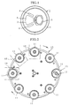
- Fig. 1 is a plan view showing a top end (manufactured article) of a usual aluminum can.
- the top end designated at 1, includes a top-end body 2 having a sector-shaped opening portion 4 surrounded by a weakened seam 3 and a tab ring (attachment) 5 securely fixed to the top-end body 2 by caulking, and is provided with lip beads 6 and 6 so as to sandwich the opening portion 4 therebetween.
- the top end of the aforesaid construction is subjected to various inspections, which includes an inspection for the presence of the tab ring 5.
- the inspection of the tab ring 5 has hitherto been conducted by making the operators check each top end 1 visually or by obtaining images of the top surface of the top end 1 with an area sensing camera and inputting the image signals to an image processing device to process the images.
- top ends has increased rapidly due to a drastic increase in the demand for aluminum cans, and hence the operators tend to suffer from considerable burdens, thereby causing inspection errors easily.
- US-A-4 140 072 describes a can lid forming apparatus including means for attaching a can opening key.
- a proximity field sensor is mounted in a doming die of the apparatus and generates a pulse logic signal as a can lid with a staked key is formed by the doming tool.
- a timing disc rotates in synchronism with each cycle of the tool and generates a pair of logic signals.
- a key monitor circuit is connected to respond to the signals to establish a latch, check latch and reset latch sequence for each cycle of the tooling. If the latch is not set, an appropriate output signal is generated indicating a key is missing from the lid. If the latch is not reset after being set, indicating a build-up of aluminum fines or the like on the probe, an appropriate signal is generated by a preconditioned probe monitoring circuit. The latter is connected to respond to the pulse logic signal and the reset signal to continuously check on the generation of the output pulse of the probe and produce a stop or alarm output if the logic pulse signal is not formed; indicating a sensor malfunction of the absence of the
- EP-A-0 304 164 describes an apparatus for inspecting the sealing surface of a container for defects. While the container is rotated, a beam of light is projected horizontally above and through a finish portion of said container. An optical detector detects the height of said sealing surface by detecting the location of a minimum in the light beam. Dips in the height indicate dips or saddles. Alternatively, an opaque bearing member is lowered onto the sealing surface in the path of the light beam to provide a reference indicative of the prevailing height of the sealing surface. Light passing between the underside of the bearing member and the sealing surface indicates a dip or saddle.
- Another object of the invention is to provide an inspection apparatus which can be utilized to carry out the aforesaid method.
- a method of inspecting a physical feature on a surface of a manufactured article comprising the steps of:
- an apparatus adapted to inspect a physical feature on a surface of a manufactured article, comprising: holding means for holding said article; first sensing means disposed adjacent to said holding means for sensing said surface of said article; and rotating means for causing one of said first sensing means and said article to rotate about an axis perpendicular to said surface of said article; characterized in that said first sensing means comprises a plurality of sensors disposed so as to sense points on said surface which are spaced by different distances from said axis perpendicular to said surface of said article to thereby produce the first signal which has peaks corresponding to the attachment on the surface of said article; and that an information obtaining means is connected to said first sensing means for comparing the positioning of the peaks of said first signal with respect to each other to thereby obtain information as to the position of the attachment on said surface of said article.
- the numeral 10 denotes a turret for holding top ends 1 for aluminum cans that are conveyed from a manufacturing line.
- the turret 10 which is in the form of a disc, is rotatable about an axis thereof, and is provided with a plurality of holding portions 11 formed on the periphery of an upper surface thereof in circumferentially equally spaced relation to one another.
- Each of the holding portions 11 has a circular shape of a diameter generally equal to the top end 1, and is rotatable about its axis.
- the top end 1 is securely received on the holding portion 11 by a vacuum, so that it can be rotated about an axis thereof by the rotation of the holding portion 11.
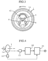
- a first sensor 12 for detecting the tab ring 5 which is, for example, comprised of an optical distance sensor (triangulation-type or quantity of reflected light-type), an ultrasonic sensor, an electrostatic sensor or an eddy-current sensor, is immovably disposed at a predetermined position above the periphery of the turret 10, and is operable to sense the distance between the sensor 12 and the top end 1 which is conveyed due to the rotation of the turret 10. As best shown in Fig.
- the first sensor 12 is located above a prescribed holding portion 11 in such a manner that when a top end 1 without any defect is received by the holding portion 11 and rotated about its axis, the sensor 12 detects the tab ring 12 at least twice and the lip beads 6, and produces a first signal representative of the information as to the tab ring.
- a second sensor 13 which may be the one similar to the aforesaid sensor, is immovably located in a fixed position adjacent to the periphery of the turret 1 for detecting the top end 1 held by the holding portion or detecting the holding portion 11 itself, to produce a second signal representative of the cycle of rotation of the top end 1.
- a slit is formed in the holding portion 11, and the second sensor 13 is arranged so as to detect the slit to produce the aforesaid second signal.
- the aforesaid first sensor 12 is connected to a signal processing circuit or unit 20 which is operable to process the signal outputted from the first sensor 12 and convert it to a binary signal based on a prescribed threshold.
- This signal processing unit 20 and the second sensor 13 are further connected to a counting circuit or an analyzer 21 which is operable to analyze the binary signal transmitted from the signal processing unit 20 with reference to the second signal representative of the cycle of rotation, to produce data or an output signal from which the operator or machine can determine whether the top end 1 held by the holding portion 11 is of good quality or not.
- a feed device 14 is disposed at a position symmetrical with respect to the axis of the turret 10 from the first sensor 12 and is operable to supply the holding portion 11, which has stopped at a position under the feed device 14, with a top end 1 which has been conveyed from the manufacturing line. Furthermore, an ejection device 15 is arranged adjacent to the feed device 14 for ejecting the top ends of good quality to a delivery line, while a discharge device 16 is disposed adjacent to the ejection device 15 for discharging defected top ends 1.
- the first and second sensors 12 and 13 are activated. Then, the first sensor 12 senses the top surface 1a of the top end 1 to produce a first signal which may have peaks produced by the presence of the tab ring 5 on the top surface 1a, and the signal processing circuit 20 processes the first signal to convert it into a binary signal, which is outputted to the analyzer 21.
- the second sensor 13 senses the rotation of the top end 1 to produce a second signal representative of the cycle of rotation of the top end 1 to input it to the analyzer 21, and in the analyzer 21, the first binary signal obtained for one cycle of rotation of the top end 1 is analyzed to produce data from which the information as to the presence of the tab ring 5 is obtained.
- the first sensor 12 when the tab ring 5 is attached properly to the top surface 1a of the top end 1, the first sensor 12 produces a first signal which has peaks P as illustrated in Fig. 5.
- the number of the detected peaks P is three when the tab ring 5 is detected at the beginning of the sensing, but is two when a portion of the surface other than the tab ring 5 is detected at the beginning.
- This first signal is converted to a binary signal based on a prescribed threshold such that the peak P corresponds to "one" while the other portions correspond to "zero".
- the binary signal thus obtained is inputted to the analyzer 21, which analyses the signal to count the number of the peaks and judges the top end 1 as being of good quality when the number of the peaks is two or three.
- the analyzer 21 judges the top end 1 as being defective.
- the signal produced by the first sensor 12 exhibits peaks lower than the aforesaid peaks P , but these lower peaks are removed during the conversion of the signal into the binary code. Any peaks caused by a foreign material adhering to the top end 1 may similarly be removed.
- the turret 10 is further rotated, and if defective, the top end 1 is discharged by the discharge device 16 while top ends 1 of good quality are ejected by the ejection device 16 to the delivery line. In this manner, the aforesaid operation is repeated to inspect all of the top ends 1 conveyed from the manufacturing line, and only the good top ends 1 are conveyed to the delivery line.
- the top surface 1a of the top end 1 is inspected while rotating the top end 1. If the tab ring 5 is properly attached to the top surface 1a, the first sensor 12 transmits a signal with at least two peaks. Therefore, the presence of the tab ring 5 can be rapidly and reliably inspected by counting the number of the peaks.
- the first sensor 12 may be constructed so as to rotate about an axis perpendicular to the top end 1.
- the inspection apparatus of the invention may be modified such that it can be used to inspect for the presence and number of irregularities on a disc-shaped article such as a badge, or to inspect any projections and recesses formed on the various manufactured articles. If a photo sensor is used as the first sensor 12, the presence and number of bright or dark portions on the articles may be inspected.
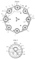
- Figs. 6 to 10 depict a modified inspection apparatus in accordance with the present invention in which a pair of first sensors 12a and 12b are immovably arranged at positions above the periphery of the turret 10 for detecting the tab ring 5 on the top end 1 which is conveyed by the rotation of the turret 10.
- the aforesaid first sensors 12a and 12b are located on a straight line passing through a diameter of the top end 1 in such a manner that the distance of the sensor 12a from the central axis of top end 1 is shorter than that of the sensor 12b therefrom, and that, when a top end 1 without defects is rotated about the central axis thereof one time, the sensor 12a detects the tab ring 5 at least twice and the lip beads 6 while the sensor 12b detects only the lip beads 6.
- the first sensors 12a and 12b are connected to signal processing units 20a and 20b, respectively, which are further connected to the analyzer 21.
- the analyzer 21 includes three AND circuits 21a and 21c and a pulse count-digital comparator 21b and is operable to process the inputted signals.
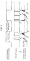
- the turret 10 is rotated as is the case with the previous embodiment, and when the top end 1 is conveyed to a position below the first sensors 12a and 12b, the first sensors 12a and 12b and the second sensor 13 are activated. Then, the second sensor 13 senses the rotation of the top end 1 to produce a second signal (ROT signal) representative of the cycle of rotation of the top end 1 to input "one" to the analyzer 21 during one cycle of rotation of the top end 1, as illustrated in Fig. 9.
- ROT signal second signal
- the first sensors 12a and 12b sense the top surface 1a of the top end 1 to produce first signals which may have peaks produced by the presence of the tab ring 5 on the top surface 1a, and the signal processing units 20a and 20b process the first signals, respectively, to convert them into binary signals, which are outputted to the analyzer 21. More specifically, when the tab ring 5 is being attached properly to the top surface 1a of the top end 1, the first sensor 12a produces a first signal which has peaks P1 based on the tab rings 5 and peaks P2 based on the lip beads 6 while the second sensor 12b produces another first signal which has peaks P3 caused by the lip beads 6, as illustrated in Fig. 9.
- the number of the detected peaks P1 and P2 of the signal produced by the first sensor 12a is four in total when a portion other than the tab ring 5 or the lip bead 6 is detected at the beginning of the sensing, and is six when the tab ring 5 or the lip beads 6 is detected at the beginning.
- the number of the detected peaks P3 of the signal produced by another first sensor 12b is two when a portion other than the lip beads 6 is detected at the beginning of the sensing, and is three when the lip bead 6 is detected at the beginning.
- the sensor 12b detects the lip bead 6 at the same time when the sensor 12a detects the tab ring 5, so that the aforesaid peaks P1 and P3 are produced simultaneously.
- the signals are converted into binary signals based on thresholds such that the peak P1, P2 or P3 corresponds to "one” while the other portions correspond to "zero", and are transmitted to the analyzer 21.
- analyzer 21 a logical AND operation is carried out by the AND circuit 21a on the binary signals to produce an IN signal, which outputs "one” when the peak P1 coincides with the peak P3 and outputs "zero" when the peaks P1 and P3 do not coincide.
- the IN signal has two or three portions indicating "one" during one cycle of rotation of the top end 1, the top end 1 is judged as being of good quality.
- the ROT signal inputted in the analyzer 21 is processed therein to produce a CK signal, which is active after the ROT signal becomes zero and remains unchanged for a prescribed period of time.
- the CK signal becomes zero before the ROT signal becomes active next time.
- the pulse count-digital comparator 21b in the analyzer 21 begins to count the number of pulses of the IN signal when the ROT signal becomes "one”, and works only when the ROT signal is active. When the ROT signal changes to "zero", the comparator 21b stops and holds the results at that time, and when the CK signal changes to "zero", it is reset and stops until the next ROT signal is produced.
- the signal produced by the sensor 12a has peaks P1 due to the tab ring 5 and peaks P2 due to the lip beads 6, while the signal produced by the sensor 12b has peaks P3 caused by the lip beads 6, as illustrated in Fig. 10.
- the peak P1 and the peak P3 emerge at different times, and hence when the signal processing operation is carried out on the binary signals of the respective signals, the IN signal thus produced has no portion indicating "one" and is outputted entirely as "zero". In this case the top end 1 is judged as being "abnormal".
- the signal processing operation is carried out on the ROT signal and the IN signal and further on the CK signal and GO/NG signal. This processed signal is outputted as “one" and the top end 1 is judged as being "abnormal".
- the signal produced by the sensor 12a does not have peaks P1. Accordingly, the IN signal produced by the AND operation on the binary signals, which are obtained similarly, has no portion that is outputted as "one", and is judged as being "abnormal".
- the tab ring 5 is attached to the proper position of the top end 1, the peak P1 due to the tab ring 5 in the signal of the sensor 12a and the peak P3 due to the lip beads 6 in the signal of the sensor 12b emerge at the same time.
- the tab ring 6 is not in the proper position, the above peaks P1 and P2 are detected at different times. Accordingly, whether the tab ring 5 is attached to the proper position or not can be easily and surely inspected by judging whether time of detection of the peaks P1 and P3 coincides or not.
- the senor 12a is arranged so that it detects the tab ring 5 and the lip beads 6 while the sensor 12b is arranged so as to detect only the lip beads 6.
- both the sensors 12a and 12b may be located so as to detect both the tab ring 5 and the lip beads 6.
- more than two sensors may be provided under some circumstances.
Landscapes
- Investigating Materials By The Use Of Optical Means Adapted For Particular Applications (AREA)
- Length Measuring Devices With Unspecified Measuring Means (AREA)
Claims (6)
- Procédé pour inspecter un accessoire (5) sur une surface (1a) d'un article fabriqué (1), comportant les étapes suivantes :(a) la disposition de moyens de détection (12) au voisinage dudit article (1) ;(b) l'utilisation desdits moyens de détection (12) pour détecter ladite surface (1a) dudit article (1) tout en faisant tourner l'un parmi lesdits moyens de détection (12) et ledit article (1) autour d'un axe perpendiculaire à ladite surface (1a) dudit article (1), afin d'obtenir par conséquent un signal concernant l'accessoire (5) ; et(c) le traitement et l'analyse ultérieurs du signal, de façon à obtenir ainsi une information concernant l'accessoire (5) sur ladite surface (1a) dudit article (1) ;caractérisé en ce que
lesdits moyens de détection (12) comportent une pluralité de détecteurs (12a, 12b) disposés de façon à détecter des points sur ladite surface (1a) qui sont espacés de distances différentes par rapport audit axe perpendiculaire à ladite surface (1a) dudit article (1) ; en ce que ladite étape d'utilisation (b) comporte l'utilisation de ladite pluralité de détecteurs (12a, 12b) afin de produire un signal qui présente des pics correspondant à l'accessoire (5) sur la surface dudit article (1a) ; et en ce que ladite étape de traitement (c) comprend l'obtention d'informations concernant la position de l'accessoire (5) sur ladite surface (1a) dudit article (1) par comparaison du positionnement des pics dudit signal les uns par rapport aux autres. - Appareil adapté à l'inspection d'un accessoire (5) sur une surface (1a) d'un article fabriqué (1), comportant :
des moyens de maintien (10, 11) pour maintenir ledit article (1) ;
des premiers moyens de détection (12) disposés au voisinage desdits moyens de maintien (10, 11) pour détecter ladite surface (1a) dudit article (1) ; et
des moyens de rotation (11) pour faire tourner l'un parmi lesdits premiers moyens de détection (12) et ledit article (1) sur un axe perpendicualire à ladite surface (1a) dudit article (1) ;
caractérisé en ce que
lesdits premiers moyens de détection (12) comportent une pluralité de détecteurs (12a, 12b) disposés de façon à détecter des points sur ladite surface (1a) qui sont espacés de distances différentes par rapport audit axe perpendiculaire à ladite surface (1a) dudit article (1) de façon à produire par conséquent un premier signal qui présente des pics correspondant à l'accessoire (5) sur la surface (1a) dudit article (1) ; et en ce que des moyens d'obtention d'information sont connectés auxdits premiers moyens de détection (12) pour comparer le positionnement des pics dudit premier signal les uns par rapport aux autres afin d'obtenir ainsi des informations concernant la position de l'accessoire (5) sur ladite surface (1a) dudit article (1). - Appareil d'inspection selon la revendication 2, dans lequel lesdits moyens d'obtention d'information comportent des deuxièmes moyens de détection (13) disposés au voisinage desdits moyens de maintien (10) pour détecter la rotation relative dudit article (1) afin de produire un deuxième signal représentatif d'une période cyclique de la rotation relative dudit article (1), une unité de traitement du signal (20a, 20b) connectée de façon opérationnelle auxdits premiers moyens de détection (12) pour traiter le premier signal, et un analyseur (21) connecté de façon opérationnelle à ladite unité de traitement du signal (20a, 20b) et auxdits deuxièmes moyens de détection (13) pour analyser les pics obtenus durant un cycle prédéterminé de rotation relative dudit article (1).
- Appareil d'inspection selon la revendication 3, dans lequel lesdits moyens de maintien comportent une tourelle (10) possédant lesdits moyens de rotation (11) qui font tourner ledit article (1).
- Appareil d'inspection selon la revendication 3, dans lequel ladite unité de traitement du signal (20a, 20b) comporte un circuit pour convertir ledit premier signal en un signal binaire.
- Appareil d'inspection selon la revendication 3, dans lequel ledit analyseur (21) comporte des moyens de comptage pour compter le nombre de pics durant un cycle de rotation relative dudit article (1) afin d'obtenir de ce fait une information concernant l'accessoire (5) sur ladite surface (1a) dudit article (1).
Priority Applications (1)
| Application Number | Priority Date | Filing Date | Title |
|---|---|---|---|
| DE1990605612 DE69005612T2 (de) | 1990-02-14 | 1990-02-14 | Verfahren und Vorrichtung zur Qualitätskontrolle von hergestellten Gegenständen. |
Applications Claiming Priority (1)
| Application Number | Priority Date | Filing Date | Title |
|---|---|---|---|
| US07/476,725 US5085515A (en) | 1990-02-08 | 1990-02-08 | Method and apparatus for inspecting quality of manufactured articles |
Publications (2)
| Publication Number | Publication Date |
|---|---|
| EP0442005A1 EP0442005A1 (fr) | 1991-08-21 |
| EP0442005B1 true EP0442005B1 (fr) | 1993-12-29 |
Family
ID=23892994
Family Applications (1)
| Application Number | Title | Priority Date | Filing Date |
|---|---|---|---|
| EP90102874A Expired - Lifetime EP0442005B1 (fr) | 1990-02-08 | 1990-02-14 | Procédé et dispositif d'examen de qualité des articles fabriqués |
Country Status (3)
| Country | Link |
|---|---|
| US (1) | US5085515A (fr) |
| EP (1) | EP0442005B1 (fr) |
| HK (1) | HK96794A (fr) |
Families Citing this family (5)
| Publication number | Priority date | Publication date | Assignee | Title |
|---|---|---|---|---|
| CA2369935A1 (fr) * | 1999-04-06 | 2000-10-12 | The Uab Research Foundation | Procede de criblage des conditions de cristallisation dans une solution de tirage d'un cristal |
| US7004302B1 (en) * | 2000-05-12 | 2006-02-28 | Fresenius Kabi Deutschland Gmbh | Turntable |
| JP3392401B2 (ja) * | 2000-12-14 | 2003-03-31 | 東洋ゴム工業株式会社 | ゴムブッシュの外筒絞り加工を行う設備 |
| US20070048059A1 (en) | 2005-08-31 | 2007-03-01 | Brother Kogyo Kabushiki Kaisha | Printer with sheet sending mechanism |
| JP6681756B2 (ja) * | 2016-03-16 | 2020-04-15 | 株式会社菊水製作所 | 回転式粉体圧縮成形機の制御装置 |
Family Cites Families (9)
| Publication number | Priority date | Publication date | Assignee | Title |
|---|---|---|---|---|
| US4075086A (en) * | 1975-04-04 | 1978-02-21 | Owens-Illinois, Inc. | Glass container handling |
| US4140072A (en) * | 1977-07-25 | 1979-02-20 | Jos. Schlitz Brewing Company | Sensing apparatus for cyclically operated apparatus |
| JPS603542A (ja) * | 1983-06-21 | 1985-01-09 | Mitsubishi Electric Corp | ビン検査装置 |
| JPS6269154A (ja) * | 1985-09-21 | 1987-03-30 | Hajime Sangyo Kk | 壜口欠陥検査装置 |
| JPH0247303B2 (ja) * | 1986-03-12 | 1990-10-19 | Toyo Seikan Kaisha Ltd | Kinzokuseihitsupariringuoseikeisurutodojinyokibutaniketsugosurusochi |
| JPS6396095A (ja) * | 1986-10-13 | 1988-04-26 | 株式会社キリンテクノシステム | 壜のねじ口部検査装置 |
| US4786801A (en) * | 1987-07-21 | 1988-11-22 | Emhart Industries Inc. | Finish Leak Detector having vertically movable light source |
| US4929828A (en) * | 1988-02-29 | 1990-05-29 | Emhart Industries, Inc. | Inspecting glass containers for line-over finish defects with bifurcated fiber optic bundle |
| US4891529A (en) * | 1988-08-22 | 1990-01-02 | View Engineering, Inc. | System and method for analyzing dimensions of can tops during manufacture |
-
1990
- 1990-02-08 US US07/476,725 patent/US5085515A/en not_active Expired - Fee Related
- 1990-02-14 EP EP90102874A patent/EP0442005B1/fr not_active Expired - Lifetime
-
1994
- 1994-09-15 HK HK96794A patent/HK96794A/en not_active IP Right Cessation
Also Published As
| Publication number | Publication date |
|---|---|
| US5085515A (en) | 1992-02-04 |
| EP0442005A1 (fr) | 1991-08-21 |
| HK96794A (en) | 1994-09-23 |
Similar Documents
| Publication | Publication Date | Title |
|---|---|---|
| EP0952443B2 (fr) | Appareil de détection de défauts au goulot et à la partie finie d'une bouteille moulée | |
| US4775889A (en) | Bottle mouth defect inspection apparatus | |
| US4584469A (en) | Optical detection of radial reflective defects | |
| EP0483966B1 (fr) | Procédé et appareil pour l'inspection d'un article transparent ou translucide telle qu'une bouteille | |
| EP0676633B1 (fr) | Inspection de la surface d'étanchéité d'un récipient | |
| US4165939A (en) | Apparatus for inspection and dimensional measurement by sequential reading | |
| JPH0989805A (ja) | 自己診断機能を有する容器の検査装置 | |
| GB2119928A (en) | Flaw detector | |
| JP4094673B2 (ja) | 検査装置、特に空き瓶検査装置の信頼性を試験するための方法 | |
| EP0763727B1 (fr) | Appareil de détection de défauts au goulot et à la partie finie d'une bouteille moulée | |
| JP3908858B2 (ja) | ガラス壜口部のびり検査装置 | |
| EP0442005B1 (fr) | Procédé et dispositif d'examen de qualité des articles fabriqués | |
| EP0040661B1 (fr) | Procédé et dispositif pour sélectionner automatiquement des boîtes vides défectueuses | |
| US5617204A (en) | Method for inspecting neck portion of molded bottle | |
| JP3417486B2 (ja) | キャップ装着不良検出方法およびその装置 | |
| WO2007061852A1 (fr) | Procede et appareil destines a l'inspection du profil des parois laterales d'un recipient | |
| US4791287A (en) | Apparatus and an associated method for detecting haze or pearlescence in containers | |
| JP7600009B2 (ja) | ツールホルダの装着状態検出方法及びツールホルダが装着される工作機械 | |
| EP1955055B1 (fr) | Appareil et procede destines a entrainer en rotation un recipient pendant son inspection | |
| PH26987A (en) | Inspection of container finish | |
| JPH06201612A (ja) | ボトルシールの外観検査方法及び装置 | |
| JP2000137004A (ja) | 表面検査装置及び表面検査方法 | |
| DE69005612T2 (de) | Verfahren und Vorrichtung zur Qualitätskontrolle von hergestellten Gegenständen. | |
| JPS62115357A (ja) | 欠陥検査装置 | |
| CA2010263A1 (fr) | Methode et appareil de controle de la qualite de produits manufactures |
Legal Events
| Date | Code | Title | Description |
|---|---|---|---|
| PUAI | Public reference made under article 153(3) epc to a published international application that has entered the european phase |
Free format text: ORIGINAL CODE: 0009012 |
|
| AK | Designated contracting states |
Kind code of ref document: A1 Designated state(s): DE FR GB |
|
| 17P | Request for examination filed |
Effective date: 19911119 |
|
| 17Q | First examination report despatched |
Effective date: 19920716 |
|
| GRAA | (expected) grant |
Free format text: ORIGINAL CODE: 0009210 |
|
| AK | Designated contracting states |
Kind code of ref document: B1 Designated state(s): DE FR GB |
|
| ET | Fr: translation filed | ||
| REF | Corresponds to: |
Ref document number: 69005612 Country of ref document: DE Date of ref document: 19940210 |
|
| PLBE | No opposition filed within time limit |
Free format text: ORIGINAL CODE: 0009261 |
|
| STAA | Information on the status of an ep patent application or granted ep patent |
Free format text: STATUS: NO OPPOSITION FILED WITHIN TIME LIMIT |
|
| 26N | No opposition filed | ||
| PGFP | Annual fee paid to national office [announced via postgrant information from national office to epo] |
Ref country code: GB Payment date: 19960130 Year of fee payment: 7 |
|
| PGFP | Annual fee paid to national office [announced via postgrant information from national office to epo] |
Ref country code: FR Payment date: 19960220 Year of fee payment: 7 |
|
| PGFP | Annual fee paid to national office [announced via postgrant information from national office to epo] |
Ref country code: DE Payment date: 19960318 Year of fee payment: 7 |
|
| PG25 | Lapsed in a contracting state [announced via postgrant information from national office to epo] |
Ref country code: GB Effective date: 19970214 |
|
| GBPC | Gb: european patent ceased through non-payment of renewal fee |
Effective date: 19970214 |
|
| PG25 | Lapsed in a contracting state [announced via postgrant information from national office to epo] |
Ref country code: FR Effective date: 19971030 |
|
| PG25 | Lapsed in a contracting state [announced via postgrant information from national office to epo] |
Ref country code: DE Effective date: 19971101 |
|
| REG | Reference to a national code |
Ref country code: FR Ref legal event code: ST |