EP0441978A1 - Vorrichtung zum aussenden von laserstrahlen - Google Patents
Vorrichtung zum aussenden von laserstrahlen Download PDFInfo
- Publication number
- EP0441978A1 EP0441978A1 EP90912952A EP90912952A EP0441978A1 EP 0441978 A1 EP0441978 A1 EP 0441978A1 EP 90912952 A EP90912952 A EP 90912952A EP 90912952 A EP90912952 A EP 90912952A EP 0441978 A1 EP0441978 A1 EP 0441978A1
- Authority
- EP
- European Patent Office
- Prior art keywords
- laser light
- excision
- prominence
- optical fiber
- emitting portion
- Prior art date
- Legal status (The legal status is an assumption and is not a legal conclusion. Google has not performed a legal analysis and makes no representation as to the accuracy of the status listed.)
- Granted
Links
- 239000013307 optical fiber Substances 0.000 claims description 21
- 239000002184 metal Substances 0.000 claims description 6
- 229910052751 metal Inorganic materials 0.000 claims description 6
- 241001465754 Metazoa Species 0.000 claims description 2
- 230000005855 radiation Effects 0.000 abstract 2
- 239000011162 core material Substances 0.000 description 13
- 229910001220 stainless steel Inorganic materials 0.000 description 9
- 239000010935 stainless steel Substances 0.000 description 9
- 239000012266 salt solution Substances 0.000 description 6
- 230000000740 bleeding effect Effects 0.000 description 4
- 230000001276 controlling effect Effects 0.000 description 3
- 230000035939 shock Effects 0.000 description 3
- VYPSYNLAJGMNEJ-UHFFFAOYSA-N Silicium dioxide Chemical compound O=[Si]=O VYPSYNLAJGMNEJ-UHFFFAOYSA-N 0.000 description 2
- 238000000034 method Methods 0.000 description 2
- 239000002245 particle Substances 0.000 description 2
- 210000001519 tissue Anatomy 0.000 description 2
- OKTJSMMVPCPJKN-UHFFFAOYSA-N Carbon Chemical compound [C] OKTJSMMVPCPJKN-UHFFFAOYSA-N 0.000 description 1
- 241000826860 Trapezium Species 0.000 description 1
- 229910052799 carbon Inorganic materials 0.000 description 1
- 239000000919 ceramic Substances 0.000 description 1
- 229910010293 ceramic material Inorganic materials 0.000 description 1
- 230000003292 diminished effect Effects 0.000 description 1
- 239000012153 distilled water Substances 0.000 description 1
- PCHJSUWPFVWCPO-UHFFFAOYSA-N gold Chemical compound [Au] PCHJSUWPFVWCPO-UHFFFAOYSA-N 0.000 description 1
- 239000010931 gold Substances 0.000 description 1
- 229910052737 gold Inorganic materials 0.000 description 1
- 230000002008 hemorrhagic effect Effects 0.000 description 1
- 230000023597 hemostasis Effects 0.000 description 1
- 239000010410 layer Substances 0.000 description 1
- 238000004519 manufacturing process Methods 0.000 description 1
- 239000000463 material Substances 0.000 description 1
- 230000004048 modification Effects 0.000 description 1
- 238000012986 modification Methods 0.000 description 1
- 238000007747 plating Methods 0.000 description 1
- 210000002307 prostate Anatomy 0.000 description 1
- 230000001105 regulatory effect Effects 0.000 description 1
- 239000000523 sample Substances 0.000 description 1
- 239000000377 silicon dioxide Substances 0.000 description 1
- 239000002344 surface layer Substances 0.000 description 1
- XLYOFNOQVPJJNP-UHFFFAOYSA-N water Chemical compound O XLYOFNOQVPJJNP-UHFFFAOYSA-N 0.000 description 1
Images


Classifications
-
- A—HUMAN NECESSITIES
- A61—MEDICAL OR VETERINARY SCIENCE; HYGIENE
- A61B—DIAGNOSIS; SURGERY; IDENTIFICATION
- A61B18/00—Surgical instruments, devices or methods for transferring non-mechanical forms of energy to or from the body
- A61B18/18—Surgical instruments, devices or methods for transferring non-mechanical forms of energy to or from the body by applying electromagnetic radiation, e.g. microwaves
- A61B18/20—Surgical instruments, devices or methods for transferring non-mechanical forms of energy to or from the body by applying electromagnetic radiation, e.g. microwaves using laser
- A61B18/22—Surgical instruments, devices or methods for transferring non-mechanical forms of energy to or from the body by applying electromagnetic radiation, e.g. microwaves using laser the beam being directed along or through a flexible conduit, e.g. an optical fibre; Couplings or hand-pieces therefor
- A61B18/24—Surgical instruments, devices or methods for transferring non-mechanical forms of energy to or from the body by applying electromagnetic radiation, e.g. microwaves using laser the beam being directed along or through a flexible conduit, e.g. an optical fibre; Couplings or hand-pieces therefor with a catheter
Definitions
- This invention relates to a lasser light emitter in use for excision of a prominence of living tissue of animal organisms.
- a high frequency scalpel is used in excision of a prominence of living tissue as a prostate.
- a high frequency scalpel has a hexagonal wire 51 (in general, it is called snare) projecting in front of a holder 50 as shown in Fig 11, and high frequency current is flown into the wire 51.
- said wire 51 is so positioned that a prominence is disposed within the wire 51 so as to cauterize to remove the prominence by heat.
- the general object of the present invention is providing a laser light emitter which can exert excision under the presence of physiorogical salt solution and can exert excision with controlling bleeding.
- the present invention features a laser light emitter comprising;an excision means , wherein a part of said excision means composes a laser light emitting portion which is capable of emitting laser light in the direction for excision of the prominence, the rest part of said excision means composes a light emission-intercepting member in the opposite side to said direction for excision of the prominence in order to shut off the laser light emission, and said laser light emitting portion is optically connected with a laser light generator.
- the present invention further features laser light emitter is made of an optical fiber covered with a metal member, a part of said laser light emitter is formed to be an excision means, at least a part of said excision means is formed as an uncovered portion in the direction for excision of the prominence and the core of said optical fiber is exposed at said uncovered portion so as to form the laser emitting portion, and the rest part of said excision means is covered with said metal member to form the laser light emission-intercepting member.
- a prominence is removed by emitting laser light.
- a laser light emitter according to the present invention is so effective for excision of hemorrhagic organism.
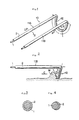
- Fig.1 is a perspective view of the first embodiment of a laser light emitter according to the present invention
- Fig.2 is a front view of the embodiment of Fig.1
- Fig.3 is a sectional view of the embodiment of Fig.1 taken on line III - III
- Fig.4 is a sectional view of the embodiment of Fig.1 taken on line IV - IV
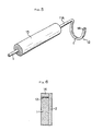
- Fig.5 is a perspective view of the second embodiment of a laser light emitter according to the present invention
- Fig.6 is a vertical sectional view of a part of the second embodiment
- Fig.7 is a plan view of the third embodiment of a laser light emitter according to the present invention
- Fig.8 and Fig.9 are perspective views of still other embodiments
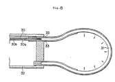
- Fig.10 is a vertical sectional view of another embodiment, wherein laser light is emitted through a light-transmissible ceramic material provided at the end of optical fiber
- Fig.11 is a plan view of a conventional apparatus.
- Fig.1-Fig4 show the first embodiment.
- An optical fiber 1 is covered with a metal member, for example a stainless-steel tube 2.
- An instrument for excision 10 provides a parallel holding portions 11A,11B and a ring-shaped portion 12 continuously connecting with the holding portion 11A and the holding portion 11B.
- a ring-shaped portion in the present invention does not mean a close-ring portion, but an open-ring portion. In fact, it is an open-loop portion.
- the ring-shaped portion 12 is projecting downward in the shape of letter U from the ends of the holding portions 11A,11B. Either side of optical fiber for example the other end of the optical fiber 1 covered with the holding portion 11A is optically connected with a laser light generator (not illustrated).
- a part of the ring-shaped portion 12 composes a laser light emitting portion L which is capable of emitting laser light in the direction C for excision the prominence M, and the rest part of the ring-shaped portion 12 composes a emission-intercepting member in the opposite side to the direction C for excision in order to shut off the laser light emission.
- the ring-shaped portion 12 is formed as an uncovered portion by a stainless-steel tube 2 on the emitting portion L and the core of the optical fiber 1 is exposed at the uncovered portion so as to form the emitting portion L, and the rest part of the ring-shaped portion 12 is covered with the stainless-steel tube 2 to form the laser light emission-intercepting member in the present invention.
- a laser light generated from the light generator is transmitted into the optical fiber 1.
- laser light is so covered with the stainless-steel tube 2 that laser light is not emitted at the covered portion. Accordingly, a part of the stainless-steel tube 2 on the emitting portion L is so opened in the direction C for excision that a laser light is emitted from the exposed portion of the core of the optical fiber 1 in Fig.2.
- Laser light is irradiated to the prominence M, and excision is done from the root of the prominence M by the excision ability of laser light.
- An operator generally holds the instrument for excision in the present invention on the holding portion 11A,11B, and then moves successiveively the instrument in the direction C for excision to exert excision.
- the core of the optical fiber 1 is directly covered with the stainless-steel tube 2, however the core of the optical fiber 1 may be covered with clad. Wherein the core of the optical fiber 1 needs to be exposed by removing of the clad on at least the emitting portion L.
- the angle ⁇ refined by the holding portion 11A,11B and the emitting portion L is 45-120° , preferably 65-85 ° .
- the parallel holding portion 11A,11B are formed to be hold, however only the holding portion 11A is formed and the emitting portion L is capable of being formed at the end of the holding portion 11A in Fig.5.
- the part designated by numeral 15 is a holder provided if needed for making easy to hold.
- a laser light reflecting portion 13 is provided at the end of the emitting portion L, wherein the reflecting portion 13 prevents laser light from being emitted at the end of the optical fiber 1 and laser light is capable of being emitted only at the side of the optical fiber 1.
- the reflecting portion 13 is providing a supporting member 14 continuously at the end of the stainless-steel tube 2 and the reflecting portion 13 is capable of being made of a reflecting material as a layer made by a gold plating positioned inside the supporting member 14.
- the emitting portion L is formed in U-shape in the above-described embodiments, when it is observed from the left side in Fig.2.
- it may be a circle or a trapezium or a rectangle (the top of every shape needs to remain discontinuous).
- Fig.7 shows a plan view of the third embodiment, and a ring-shaped porton 12A is formed at the end of a holder 20. A part of stainless-steel tube 2 is broken away and the core of the optical fiber 1 is exposed as shown in the first embodiment.
- the ring-shaped portion 12 is so positioned that the prominence is disposed within the ring-shaped portion 12A like a conventional snare, and then the ring-shaped portion 12A is moved in the direction C to exert excision by laser light irradiation.
- the holder 20 can be omitted.
- the emitting portion is formed on almost the whole of the ring-shaped portion 12 or 12A, however in the first embodiment the emitting portion can be formed only at the bottom of the U-shaped portion and in the third embodiment the emitting portion can be formed only on the right half of the ring-shaped portion.
- the core of the optical fiber is covered with a metal member for example stainless-steel tube from the point of view of strength.
- a light emitter can be formed of single optical fiber covered with a clad, wherein the clad is partly broken away and the core is exposed to form the emitting portion.
- the clad is equivalent to the light emission-intercepting portion in the present invention.
- an emitting member 31 made of a light-transmissible ceramic for example bent into ring-shape having circular cross section is provided at the end of an optical fiber 30 having a core 30a and a clad 30b, and laser light exited at the end of the core 30a of the optical fiber 30 enters into the emitting member 31, and then laser light is capable of being emitted from the emitting member 31.
- the part designated by numeral 32 is a holder and the part designated by numeral 33 is the instrument for connecting. Such method of the indirect incidence is applicable in the first embodiment and the second embodiment.
- Fig.9 and Fig.10 respectively corresponding to Fig.1 and Fig.5
- the core 1 is be so formed that its diameter gradually gets thinner. Then the quantity of emitted laser light increases at the diminished portion as with the case of a slender conic probe, so the laser light can be led to the direction for excision more effectively.
- the surface of a laser light emitting portion can be provided with the surface layer for diffusing of laser light if needed.
- a laser light absorbing particle as carbon or a laser light diffusing particle as silica having larger refractive index than that of an emitting member as a core material can be utilized.
- the surface of a laser light emitting portion can be provided with a roughened surface to raise diffusing.
- a laser light emitter in the present invention is capable of being used in an operation by using endoscope as well as a surgical operation.
Landscapes
- Health & Medical Sciences (AREA)
- Surgery (AREA)
- Physics & Mathematics (AREA)
- Life Sciences & Earth Sciences (AREA)
- Heart & Thoracic Surgery (AREA)
- Animal Behavior & Ethology (AREA)
- Nuclear Medicine, Radiotherapy & Molecular Imaging (AREA)
- Electromagnetism (AREA)
- Engineering & Computer Science (AREA)
- Biomedical Technology (AREA)
- Optics & Photonics (AREA)
- Medical Informatics (AREA)
- Molecular Biology (AREA)
- Otolaryngology (AREA)
- General Health & Medical Sciences (AREA)
- Public Health (AREA)
- Veterinary Medicine (AREA)
- Laser Surgery Devices (AREA)
- Radiation-Therapy Devices (AREA)
- Laser Beam Processing (AREA)
- Lasers (AREA)
- Semiconductor Lasers (AREA)
Applications Claiming Priority (3)
| Application Number | Priority Date | Filing Date | Title |
|---|---|---|---|
| JP227092/89 | 1989-09-01 | ||
| JP1227092A JP3069108B2 (ja) | 1989-09-01 | 1989-09-01 | レーザ光の出射装置 |
| PCT/JP1990/001108 WO1991003206A1 (en) | 1989-09-01 | 1990-08-30 | Device for radiating laser beams |
Publications (3)
| Publication Number | Publication Date |
|---|---|
| EP0441978A1 true EP0441978A1 (de) | 1991-08-21 |
| EP0441978A4 EP0441978A4 (en) | 1992-04-22 |
| EP0441978B1 EP0441978B1 (de) | 1994-06-15 |
Family
ID=16855367
Family Applications (1)
| Application Number | Title | Priority Date | Filing Date |
|---|---|---|---|
| EP90912952A Expired - Lifetime EP0441978B1 (de) | 1989-09-01 | 1990-08-30 | Vorrichtung zum aussenden von laserstrahlen |
Country Status (11)
| Country | Link |
|---|---|
| US (1) | US5151097A (de) |
| EP (1) | EP0441978B1 (de) |
| JP (1) | JP3069108B2 (de) |
| CN (1) | CN1051667A (de) |
| AT (1) | ATE107153T1 (de) |
| AU (1) | AU6281890A (de) |
| CA (1) | CA2038949A1 (de) |
| DE (1) | DE69009976T2 (de) |
| ES (1) | ES2057586T3 (de) |
| WO (1) | WO1991003206A1 (de) |
| ZA (1) | ZA906920B (de) |
Families Citing this family (38)
| Publication number | Priority date | Publication date | Assignee | Title |
|---|---|---|---|---|
| US5195958A (en) * | 1990-05-25 | 1993-03-23 | Phillips Edward H | Tool for laparoscopic surgery |
| US5300063A (en) * | 1991-05-11 | 1994-04-05 | Nidek Co., Ltd. | Ophthalmic laser apparatus |
| DE59208936D1 (de) * | 1991-07-17 | 1997-11-06 | Siemens Ag | Handstück zur stomatologischen Applikation von Laserlicht |
| US5688264A (en) * | 1992-10-19 | 1997-11-18 | The University Of Miami | Laser treatment for retinal detachment |
| US5342358A (en) * | 1993-01-12 | 1994-08-30 | S.L.T. Japan Co., Ltd. | Apparatus for operation by laser energy |
| US5451221A (en) * | 1993-12-27 | 1995-09-19 | Cynosure, Inc. | Endoscopic light delivery system |
| US5668993A (en) | 1994-02-28 | 1997-09-16 | Teleflex Information Systems, Inc. | Multithreaded batch processing system |
| US5476461A (en) * | 1994-05-13 | 1995-12-19 | Cynosure, Inc. | Endoscopic light delivery system |
| US6558375B1 (en) * | 2000-07-14 | 2003-05-06 | Cardiofocus, Inc. | Cardiac ablation instrument |
| US8025661B2 (en) | 1994-09-09 | 2011-09-27 | Cardiofocus, Inc. | Coaxial catheter instruments for ablation with radiant energy |
| US5632767A (en) * | 1994-09-09 | 1997-05-27 | Rare Earth Medical, Inc. | Loop diffusers for diffusion of optical radiation |
| US6423055B1 (en) | 1999-07-14 | 2002-07-23 | Cardiofocus, Inc. | Phototherapeutic wave guide apparatus |
| US6270492B1 (en) | 1994-09-09 | 2001-08-07 | Cardiofocus, Inc. | Phototherapeutic apparatus with diffusive tip assembly |
| US5947959A (en) * | 1994-09-09 | 1999-09-07 | Rare Earth Medical, Inc. | Phototherapeutic apparatus with diffusive tip assembly |
| US6579285B2 (en) * | 1994-09-09 | 2003-06-17 | Cardiofocus, Inc. | Photoablation with infrared radiation |
| US6676656B2 (en) * | 1994-09-09 | 2004-01-13 | Cardiofocus, Inc. | Surgical ablation with radiant energy |
| US5908415A (en) * | 1994-09-09 | 1999-06-01 | Rare Earth Medical, Inc. | Phototherapy methods and apparatus |
| US5637877A (en) * | 1995-06-06 | 1997-06-10 | Rare Earth Medical, Inc. | Ultraviolet sterilization of instrument lumens |
| US9033961B2 (en) | 1999-07-14 | 2015-05-19 | Cardiofocus, Inc. | Cardiac ablation catheters for forming overlapping lesions |
| US7935108B2 (en) | 1999-07-14 | 2011-05-03 | Cardiofocus, Inc. | Deflectable sheath catheters |
| US8900219B2 (en) | 1999-07-14 | 2014-12-02 | Cardiofocus, Inc. | System and method for visualizing tissue during ablation procedures |
| US8540704B2 (en) | 1999-07-14 | 2013-09-24 | Cardiofocus, Inc. | Guided cardiac ablation catheters |
| US20040167503A1 (en) * | 1999-08-25 | 2004-08-26 | Cardiofocus, Inc. | Malleable surgical ablation instruments |
| US20040147911A1 (en) * | 1999-08-25 | 2004-07-29 | Cardiofocus, Inc. | Surgical ablation instruments for forming an encircling lesion |
| AU2003245573A1 (en) | 2002-06-19 | 2004-01-06 | Palomar Medical Technologies, Inc. | Method and apparatus for treatment of cutaneous and subcutaneous conditions |
| US7731715B2 (en) * | 2004-12-10 | 2010-06-08 | Edwards Lifesciences Corporation | Ablative treatment of atrial fibrillation via the coronary sinus |
| US20060253025A1 (en) * | 2005-04-21 | 2006-11-09 | Kaufman Jonathan J | Ultrasonic Bone Assessment Apparatus and Method |
| US7856985B2 (en) | 2005-04-22 | 2010-12-28 | Cynosure, Inc. | Method of treatment body tissue using a non-uniform laser beam |
| DE102006016957B4 (de) * | 2006-04-11 | 2010-04-22 | Vimecon Gmbh | Laserapplikator |
| US7586957B2 (en) | 2006-08-02 | 2009-09-08 | Cynosure, Inc | Picosecond laser apparatus and methods for its operation and use |
| US8696653B2 (en) | 2009-10-02 | 2014-04-15 | Cardiofocus, Inc. | Cardiac ablation system with pulsed aiming light |
| WO2011044248A2 (en) | 2009-10-06 | 2011-04-14 | Cardiofocus, Inc. | Cardiac ablation image analysis system and process |
| JP2015510142A (ja) * | 2012-01-31 | 2015-04-02 | アシメトリック メディカル リミテッド | 曲げによって放射線を発するように構成される光ファイバ |
| WO2013158299A1 (en) | 2012-04-18 | 2013-10-24 | Cynosure, Inc. | Picosecond laser apparatus and methods for treating target tissues with same |
| EP2973894A2 (de) | 2013-03-15 | 2016-01-20 | Cynosure, Inc. | Optische picosekunden-strahlungssysteme und verfahren zur verwendung |
| JP2017513645A (ja) | 2014-04-28 | 2017-06-01 | カーディオフォーカス,インコーポレーテッド | アブレーション処置の際にicg色素組成物を用いて組織を視覚化するためのシステムおよび方法 |
| WO2016089900A2 (en) | 2014-12-03 | 2016-06-09 | Cardiofocus, Inc. | System and method for visual confirmation of pulmonary vein isolation during ablation procedures |
| CN112042066A (zh) | 2018-02-26 | 2020-12-04 | 赛诺秀股份有限公司 | 调q倾腔亚纳秒激光器 |
Family Cites Families (13)
| Publication number | Priority date | Publication date | Assignee | Title |
|---|---|---|---|---|
| US4126136A (en) * | 1976-02-09 | 1978-11-21 | Research Corporation | Photocoagulating scalpel system |
| US4240431A (en) * | 1977-05-16 | 1980-12-23 | Olympus Optical Co., Ltd. | Laser knife |
| US4266547A (en) * | 1977-05-16 | 1981-05-12 | Olympus Optical Co., Ltd. | Laser knife |
| US4249533A (en) * | 1977-05-16 | 1981-02-10 | Olympus Optical Co., Ltd. | Laser knife |
| DE2821376C3 (de) * | 1977-05-16 | 1981-02-19 | Olympus Optical Co., Ltd., Tokio | Laser-Instrument zum Ätzen oder Veröden eines Gewebeteils innerhalb des Zöloms |
| JPS5710648Y2 (de) * | 1977-06-24 | 1982-03-02 | ||
| US4273127A (en) * | 1978-10-12 | 1981-06-16 | Research Corporation | Method for cutting and coagulating tissue |
| JPS5810039A (ja) * | 1981-07-13 | 1983-01-20 | 住友電気工業株式会社 | レ−ザメス用ハンドピ−ス |
| US4693244A (en) * | 1984-05-22 | 1987-09-15 | Surgical Laser Technologies, Inc. | Medical and surgical laser probe I |
| US4736743A (en) * | 1986-05-12 | 1988-04-12 | Surgical Laser Technology, Inc. | Vaporization contact laser probe |
| JPS62202815U (de) * | 1986-06-13 | 1987-12-24 | ||
| JPS63216579A (ja) * | 1987-03-05 | 1988-09-08 | 大工園 則雄 | 温熱治療のためのレ−ザ光照射装置 |
| JP2671016B2 (ja) * | 1988-07-08 | 1997-10-29 | サージカル・レーザー・テクノロジーズ・インコーポレイテッド | 生体組織内狭隘路におけるレーザ治療装置 |
-
1989
- 1989-09-01 JP JP1227092A patent/JP3069108B2/ja not_active Expired - Lifetime
-
1990
- 1990-08-28 US US07/573,563 patent/US5151097A/en not_active Expired - Fee Related
- 1990-08-30 EP EP90912952A patent/EP0441978B1/de not_active Expired - Lifetime
- 1990-08-30 WO PCT/JP1990/001108 patent/WO1991003206A1/ja not_active Ceased
- 1990-08-30 ZA ZA906920A patent/ZA906920B/xx unknown
- 1990-08-30 AT AT90912952T patent/ATE107153T1/de not_active IP Right Cessation
- 1990-08-30 ES ES90912952T patent/ES2057586T3/es not_active Expired - Lifetime
- 1990-08-30 AU AU62818/90A patent/AU6281890A/en not_active Abandoned
- 1990-08-30 CA CA002038949A patent/CA2038949A1/en not_active Abandoned
- 1990-08-30 DE DE69009976T patent/DE69009976T2/de not_active Expired - Fee Related
- 1990-08-31 CN CN90108169A patent/CN1051667A/zh active Pending
Also Published As
| Publication number | Publication date |
|---|---|
| US5151097A (en) | 1992-09-29 |
| JP3069108B2 (ja) | 2000-07-24 |
| DE69009976T2 (de) | 1995-03-02 |
| JPH0390143A (ja) | 1991-04-16 |
| EP0441978A4 (en) | 1992-04-22 |
| AU6281890A (en) | 1991-04-08 |
| ZA906920B (en) | 1991-06-26 |
| CA2038949A1 (en) | 1991-03-02 |
| ATE107153T1 (de) | 1994-07-15 |
| ES2057586T3 (es) | 1994-10-16 |
| WO1991003206A1 (en) | 1991-03-21 |
| DE69009976D1 (de) | 1994-07-21 |
| EP0441978B1 (de) | 1994-06-15 |
| CN1051667A (zh) | 1991-05-29 |
Similar Documents
| Publication | Publication Date | Title |
|---|---|---|
| EP0441978A1 (de) | Vorrichtung zum aussenden von laserstrahlen | |
| JP2779825B2 (ja) | レーザ光出射装置 | |
| JP3148216B2 (ja) | レーザ光照射による治療装置 | |
| US4693244A (en) | Medical and surgical laser probe I | |
| US4718416A (en) | Laser treatment apparatus | |
| JP2681073B2 (ja) | レーザ光出射プローブとその製造方法 | |
| EP0637942B1 (de) | Medizinische vorrichtung | |
| JP3145379B2 (ja) | レーザ導光プローブ | |
| US6673065B1 (en) | Slender tip laser scalpel | |
| US20020183728A1 (en) | Laser probe | |
| JP2683565B2 (ja) | レーザ光の透過体およびその製造方法 | |
| WO1985005262A1 (en) | Medical and surgical laser probe i | |
| EP0424272A2 (de) | Vorrichtung zur Bestrahlung mit Laserlicht | |
| EP0227258A2 (de) | Chirurgische Vorrichtung zum Schneiden und Bohren | |
| RU2038106C1 (ru) | Лазерное излучающее устройство для медицинской обработки | |
| WO2007034526A1 (en) | Multifiber instrument for contact laser surgery | |
| JP3415284B2 (ja) | レーザー導光体の処理方法とその装置 | |
| CN119488355A (zh) | 一种激光冲击波碎石成像装置 | |
| RU145125U1 (ru) | Лазерная установка для абляции полых анатомических структур | |
| Russo et al. | A novel corolla-irradiating fiber optic probe for laser angioplasty | |
| Verdaasdonck et al. | What makes a fiber tip do the job: an optical and thermal evaluation study | |
| Peshko et al. | Fiber photo-catheters with spatially modulated diffusers for laser treatment of atrial fibrillation | |
| JPH0299048A (ja) | 内視鏡用レーザメス | |
| JPH0667390B2 (ja) | 光ファイバーケーブル | |
| JPS63147452A (ja) | フアイバ−治療器具 |
Legal Events
| Date | Code | Title | Description |
|---|---|---|---|
| PUAI | Public reference made under article 153(3) epc to a published international application that has entered the european phase |
Free format text: ORIGINAL CODE: 0009012 |
|
| 17P | Request for examination filed |
Effective date: 19910515 |
|
| AK | Designated contracting states |
Kind code of ref document: A1 Designated state(s): AT CH DE ES FR GB IT LI NL SE |
|
| A4 | Supplementary search report drawn up and despatched |
Effective date: 19920303 |
|
| AK | Designated contracting states |
Kind code of ref document: A4 Designated state(s): AT CH DE ES FR GB IT LI NL SE |
|
| 17Q | First examination report despatched |
Effective date: 19930115 |
|
| GRAA | (expected) grant |
Free format text: ORIGINAL CODE: 0009210 |
|
| AK | Designated contracting states |
Kind code of ref document: B1 Designated state(s): AT CH DE ES FR GB IT LI NL SE |
|
| REF | Corresponds to: |
Ref document number: 107153 Country of ref document: AT Date of ref document: 19940715 Kind code of ref document: T |
|
| REF | Corresponds to: |
Ref document number: 69009976 Country of ref document: DE Date of ref document: 19940721 |
|
| ITF | It: translation for a ep patent filed | ||
| ET | Fr: translation filed | ||
| REG | Reference to a national code |
Ref country code: ES Ref legal event code: FG2A Ref document number: 2057586 Country of ref document: ES Kind code of ref document: T3 |
|
| EAL | Se: european patent in force in sweden |
Ref document number: 90912952.0 |
|
| PLBE | No opposition filed within time limit |
Free format text: ORIGINAL CODE: 0009261 |
|
| STAA | Information on the status of an ep patent application or granted ep patent |
Free format text: STATUS: NO OPPOSITION FILED WITHIN TIME LIMIT |
|
| 26N | No opposition filed | ||
| PGFP | Annual fee paid to national office [announced via postgrant information from national office to epo] |
Ref country code: AT Payment date: 20000817 Year of fee payment: 11 |
|
| PGFP | Annual fee paid to national office [announced via postgrant information from national office to epo] |
Ref country code: SE Payment date: 20000821 Year of fee payment: 11 |
|
| PGFP | Annual fee paid to national office [announced via postgrant information from national office to epo] |
Ref country code: GB Payment date: 20000823 Year of fee payment: 11 |
|
| PGFP | Annual fee paid to national office [announced via postgrant information from national office to epo] |
Ref country code: NL Payment date: 20000824 Year of fee payment: 11 |
|
| PGFP | Annual fee paid to national office [announced via postgrant information from national office to epo] |
Ref country code: DE Payment date: 20000828 Year of fee payment: 11 |
|
| PGFP | Annual fee paid to national office [announced via postgrant information from national office to epo] |
Ref country code: FR Payment date: 20000829 Year of fee payment: 11 |
|
| PGFP | Annual fee paid to national office [announced via postgrant information from national office to epo] |
Ref country code: ES Payment date: 20000919 Year of fee payment: 11 Ref country code: CH Payment date: 20000919 Year of fee payment: 11 |
|
| PG25 | Lapsed in a contracting state [announced via postgrant information from national office to epo] |
Ref country code: GB Free format text: LAPSE BECAUSE OF NON-PAYMENT OF DUE FEES Effective date: 20010830 Ref country code: AT Free format text: LAPSE BECAUSE OF NON-PAYMENT OF DUE FEES Effective date: 20010830 |
|
| PG25 | Lapsed in a contracting state [announced via postgrant information from national office to epo] |
Ref country code: SE Free format text: LAPSE BECAUSE OF NON-PAYMENT OF DUE FEES Effective date: 20010831 Ref country code: LI Free format text: LAPSE BECAUSE OF NON-PAYMENT OF DUE FEES Effective date: 20010831 Ref country code: ES Free format text: LAPSE BECAUSE OF NON-PAYMENT OF DUE FEES Effective date: 20010831 Ref country code: CH Free format text: LAPSE BECAUSE OF NON-PAYMENT OF DUE FEES Effective date: 20010831 |
|
| PG25 | Lapsed in a contracting state [announced via postgrant information from national office to epo] |
Ref country code: NL Free format text: LAPSE BECAUSE OF NON-PAYMENT OF DUE FEES Effective date: 20020301 |
|
| EUG | Se: european patent has lapsed |
Ref document number: 90912952.0 |
|
| REG | Reference to a national code |
Ref country code: CH Ref legal event code: PL |
|
| PG25 | Lapsed in a contracting state [announced via postgrant information from national office to epo] |
Ref country code: FR Free format text: LAPSE BECAUSE OF NON-PAYMENT OF DUE FEES Effective date: 20020430 |
|
| NLV4 | Nl: lapsed or anulled due to non-payment of the annual fee |
Effective date: 20020301 |
|
| PG25 | Lapsed in a contracting state [announced via postgrant information from national office to epo] |
Ref country code: DE Free format text: LAPSE BECAUSE OF NON-PAYMENT OF DUE FEES Effective date: 20020501 |
|
| REG | Reference to a national code |
Ref country code: FR Ref legal event code: ST |
|
| REG | Reference to a national code |
Ref country code: ES Ref legal event code: FD2A Effective date: 20020911 |
|
| PG25 | Lapsed in a contracting state [announced via postgrant information from national office to epo] |
Ref country code: IT Free format text: LAPSE BECAUSE OF NON-PAYMENT OF DUE FEES;WARNING: LAPSES OF ITALIAN PATENTS WITH EFFECTIVE DATE BEFORE 2007 MAY HAVE OCCURRED AT ANY TIME BEFORE 2007. THE CORRECT EFFECTIVE DATE MAY BE DIFFERENT FROM THE ONE RECORDED. Effective date: 20050830 |