EP0441283A2 - Kükenhahn für abrasive Medien - Google Patents
Kükenhahn für abrasive Medien Download PDFInfo
- Publication number
- EP0441283A2 EP0441283A2 EP91101438A EP91101438A EP0441283A2 EP 0441283 A2 EP0441283 A2 EP 0441283A2 EP 91101438 A EP91101438 A EP 91101438A EP 91101438 A EP91101438 A EP 91101438A EP 0441283 A2 EP0441283 A2 EP 0441283A2
- Authority
- EP
- European Patent Office
- Prior art keywords
- plug
- lining
- outer housing
- ceramic
- tap
- Prior art date
- Legal status (The legal status is an assumption and is not a legal conclusion. Google has not performed a legal analysis and makes no representation as to the accuracy of the status listed.)
- Granted
Links
Images

Classifications
-
- F—MECHANICAL ENGINEERING; LIGHTING; HEATING; WEAPONS; BLASTING
- F16—ENGINEERING ELEMENTS AND UNITS; GENERAL MEASURES FOR PRODUCING AND MAINTAINING EFFECTIVE FUNCTIONING OF MACHINES OR INSTALLATIONS; THERMAL INSULATION IN GENERAL
- F16K—VALVES; TAPS; COCKS; ACTUATING-FLOATS; DEVICES FOR VENTING OR AERATING
- F16K5/00—Plug valves; Taps or cocks comprising only cut-off apparatus having at least one of the sealing faces shaped as a more or less complete surface of a solid of revolution, the opening and closing movement being predominantly rotary
- F16K5/04—Plug valves; Taps or cocks comprising only cut-off apparatus having at least one of the sealing faces shaped as a more or less complete surface of a solid of revolution, the opening and closing movement being predominantly rotary with plugs having cylindrical surfaces; Packings therefor
- F16K5/045—Particular coverings and materials
-
- F—MECHANICAL ENGINEERING; LIGHTING; HEATING; WEAPONS; BLASTING
- F16—ENGINEERING ELEMENTS AND UNITS; GENERAL MEASURES FOR PRODUCING AND MAINTAINING EFFECTIVE FUNCTIONING OF MACHINES OR INSTALLATIONS; THERMAL INSULATION IN GENERAL
- F16K—VALVES; TAPS; COCKS; ACTUATING-FLOATS; DEVICES FOR VENTING OR AERATING
- F16K27/00—Construction of housing; Use of materials therefor
- F16K27/06—Construction of housing; Use of materials therefor of taps or cocks
- F16K27/065—Construction of housing; Use of materials therefor of taps or cocks with cylindrical plugs
Definitions
- the invention relates to a plug valve for abrasive media according to the preamble of claim 1.
- the tap housing of the plug valve consists of an outer housing and a liner held in the outer housing.
- the outer housing of the plug valve consists of several interconnected parts, which are made of gray cast iron, a material of relatively high mechanical strength but low abrasion resistance.
- the lining held in the outer housing consists of a plurality of nested parts which are made of ceramic, a material of low tensile and bending strength but high abrasion and corrosion resistance. All parts of the lining are supported on the outer housing. They are therefore only subjected to pressure.
- the cock plug is also made of ceramic; it is rotatably mounted in a bush formed by part of the lining. This part forms the central part of the lining.
- the central part of the lining On its outside it is provided with recesses into which the connecting pieces leading to the connections of the plug valve are inserted.
- the central part of the lining is secured against rotation relative to the outer housing only after the connecting pieces have been inserted.
- the central part of the lining has different wall thicknesses, which prevent the lining from being optimized with regard to sudden temperature changes. If ceramic parts are used as the lining of a valve, there is a risk of cracking in ceramic parts, particularly if the temperature changes suddenly different wall thickness. Due to the low elasticity of ceramic parts, uneven heating of the ceramic parts leads to crack propagation of the "crack nuclei" that are always present in the ceramic parts. In addition, the production of the central part of the lining is very complex due to the complicated shape.
- the invention is therefore based on the object of providing a plug valve of the type mentioned at the outset, in which the production outlay is minimized and which permits optimization of the wall thickness of the lining with regard to sudden temperature changes in the medium flowing through the plug valve.
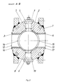
- Figures 1 and 2 show different views of a plug valve according to the invention.
- the left half of Figure 1 is shown as a vertical section through the plug valve and the right half of Figure 1 as a side view.
- the cock plug and the plates that close the openings for the installation of the plug pipe in the outer housing are shown in the manner of an exploded drawing.
- the faucet housing consists of a solid outer housing 1 made of austenitic steel and of a lining held in the outer housing 1, which is formed from three ceramic tubes, the plug tube 2 and the connecting tubes 3 and 4.
- the plug tube 2 is secured against rotation with respect to the outer housing 1 by two bolts 5 and 6 made of ceramic.
- the bolts 5 and 6 extend from the outer housing 1 into the wall of the plug tube 2.
- Seals 7 and 8 seal the bolts 5 and 6 against the outer housing 1. Plates 9 and 10, which are screwed to the outer housing 1, close the outer housing and hold the bolts 5 and 6 in place.
- the cock plug 11 is rotatably mounted in the plug pipe 2.
- the connecting pipes 3 and 4 connect the connections 12 and 13 to the plug pipe 2.
- the connecting pipes 3 and 4 have on one end face a recess 14 and 15, respectively, which is adapted to the cylindrical curvature of the outer surface of the plug pipe 2. These recesses can be made by a simple grinding process.
- the plug tube 2 is inserted and aligned so that the holes for receiving the bolts 5 and 6 are aligned.
- the bolts 5 and 6 are inserted and the outer housing 1 is closed by the plates 9 and 10.
- the connecting pipes 3 and 4 are inserted into the outer housing 1 by the connections 12 and 13 and secured by means of silicone compound 16 and 17 for transport.
- the connecting pipes 3 and 4 are through the to the Connections 12 and 13 connected pipes secured.
- the cock plug 11 is inserted into the plug pipe 2, and the plates 18 and 19 are screwed to the outer housing 1.
- the plates 18 and 19 close the outer housing 1 and prevent axial movement of the cock plug 11.
- the wall thickness of the ceramic tubes forming the lining of the outer housing is the same everywhere. The wall thickness can therefore be easily optimized for thermal shock resistance.
Landscapes
- Engineering & Computer Science (AREA)
- General Engineering & Computer Science (AREA)
- Mechanical Engineering (AREA)
- Valve Housings (AREA)
- Lift Valve (AREA)
- Sliding Valves (AREA)
Abstract
Description
- Die Erfindung betrifft einen Kükenhahn für abrasive Medien gemäß dem Oberbegriff des Anspruchs 1.
- Ein derartiger Kükenhahn ist aus der DE-OS 36 42 872 bekannt. Das Hahngehäuse des Kükenhahns besteht aus einem Außengehäuse und einer in dem Außengehäuse gehaltenen Auskleidung. Das Außengehäuse des Kükenhahns besteht aus mehreren miteinander verbundenen Teilen, die aus Grauguß, einem Material relativ hoher mechanischer Festigkeit aber geringer Abriebsbeständigkeit, hergestellt sind. Die in dem Außengehäuse gehaltene Auskleidung besteht aus mehreren ineinander gesteckten Teilen, die aus Keramik, einem Material geringer Zug- und Biegefestigkeit aber hoher Abrieb- und Korrosionsbeständigkeit, hergestellt sind. Alle Teile der Auskleidung stützen sich an dem Außengehäuse ab. Sie werden daher nur auf Druck beansprucht. Das Hahnküken besteht ebenfalls aus Keramik; es ist in einer, von einem Teil der Auskleidung gebildeten Buchse, drehbar gelagert. Dieses Teil bildet das zentrale Teil der Auskleidung. Auf seiner Außenseite ist es mit Ausnehmungen versehen, in die die zu den Anschlüssen des Kükenhahns führenden Anschlußstücke gesteckt werden. Erst nach dem Einstecken der Anschlußstücke ist das zentrale Teil der Auskleidung gegen eine Verdrehung gegenüber dem Außengehäuse gesichert. Das zentrale Teil der Auskleidung weist unterschiedliche Wandstärken auf, die eine Optimierung der Auskleidung im Hinblick auf sprungartige Temperaturänderungen verhindern. Werden Keramikteile als Auskleidung eines Ventils verwendet, besteht besonders bei einer sprungartigen Änderung der Temperatur die Gefahr von Rißbildungen in Keramikteilen mit unterschiedlicher Wandstärke. Aufgrund der geringen Elastizität von Keramikteilen führt eine ungleichmäßige Erwärmung der Keramikteile zu einem Rißfortschritt der in den Keramikteilen immer vorhandenen "Rißkeime" . Dazu kommt, daß die Fertigung des zentralen Teils der Auskleidung aufgrund der komplizierten Formgebung sehr aufwendig ist.
- Der Erfindung liegt daher die Aufgabe zugrunde, einen Kükenhahn der eingangs genannten Art zu schaffen, bei dem der Fertigungsaufwand minimiert wird und der eine Optimierung der Wandstärke der Auskleidung im Hinblick auf sprungartige Temperaturänderungen des durch den Kükenhahn fließenden Mediums erlaubt.
- Diese Aufgabe wird erfindungsgemäß durch die im Kennzeichen des Patentanspruchs angegebenen Merkmale gelöst. Temperaturbedingte Formänderungen sind bei dem erfindungsgemäßen Kükenhahn so gering, daß die Keramikteile nicht durch äußere Kräfte belastet werden. Falls erforderlich, können die Keramikteile auf einfache Weise ausgetauscht werden. Für eine Demontage des Kükenrohres braucht der Kükenhahn nicht aus dem Leitungszug ausgebaut zu werden.
- Ein Ausführungsbeispiel der Erfindung wird anhand der nachfolgenden Zeichnungen näher erläutert. Es zeigen
- Figur 1
- eine Seitenansicht des erfindungsgemäßen Kükenhahnes, dessen eine Hälfte als Schnitt dargestellt ist, wobei einzelne Teile des Kükenhahnes in der Art einer Explosionszeichnung dargestellt sind, und
- Figur 2
- einen waagerechten Schnitt durch den erfindungsgemäßen Kükenhahn entlang der Linie A - B in der Figur 1.
- Die Figuren 1 und 2 zeigen verschiedene Ansichten eines Kükenhahnes nach der Erfindung. Die linke Hälfte der Figur 1 ist als senkrechter Schnitt durch den Kükenhahn dargestellt und die rechte Hälfte der Figur 1 als Seitenansicht. Das Hahnküken und die Platten, die die Öffnungen für den Einbau des Kükenrohres in das Außengehäuse verschließen, sind dabei in der Art einer Explosionszeichnung dargestellt. Das Hahngehäuse besteht aus einem aus austenitischem Stahl hergestellten massiven Außengehäuse 1 und aus einer in dem Außengehäuse 1 gehaltenen Auskleidung, die aus drei Keramikrohren, dem Kükenrohr 2 und den Anschlußrohren 3 und 4, gebildet ist. Das Kükenrohr 2 ist durch zwei aus Keramik hergestellte Bolzen 5 und 6 gegen Verdrehung gegenüber dem Außengehäuse 1 gesichert. Die Bolzen 5 und 6 erstrecken sich von dem Außengehäuse 1 bis in die Wand des Kükenrohres 2. Dichtungen 7 und 8 dichten die Bolzen 5 bzw. 6 gegen das Außengehäuse 1 ab. Platten 9 und 10, die mit dem Außengehäuse 1 verschraubt sind, verschließen das Außengehäuse und halten die Bolzen 5 und 6 an ihrem Platz. In dem Kükenrohr 2 ist das Hahnküken 11 drehbar gelagert. Die Anschlußrohre 3 und 4 verbinden die Anschlüsse 12 und 13 mit dem Kükenrohr 2. Die Anschlußrohre 3 und 4 weisen an ihrer einen Stirnseite eine an die zylinderförmige Wölbung der Außenfläche des Kükenrohres 2 angepaßte Ausnehmung 14 bzw. 15 auf. Diese Ausnehmungen lassen sich durch einen einfachen Schleifvorgang herstellen.
- Im folgenden ist der Zusammenbau des erfindungsgemäßen Kükenhahnes beschrieben. In das Außengehäuse 1 wird das Kükenrohr 2 eingeschoben und so ausgerichtet, daß die Bohrungen für die Aufnahme der Bolzen 5 und 6 fluchten. Die Bolzen 5 und 6 werden eingesetzt und das Außengehäuse 1 durch die Platten 9 und 10 verschlossen. Die Anschlußrohre 3 und 4 werden von den Anschlüssen 12 bzw. 13 in das Außengehäuse 1 eingeschoben und durch Silikonmasse 16 bzw. 17 für den Transport gesichert. Nach dem Einbau des erfindungsgemäßen Kükenhahnes in einen Leitungszug sind die Anschlußrohre 3 und 4 durch die an die Anschlüsse 12 und 13 angeschlosssenen Rohrleitungen gesichert. Das Hahnküken 11 wird in das Kükenrohr 2 eingeschoben, und die Platten 18 und 19 werden mit dem Außengehäuse 1 verschraubt. Die Platten 18 und 19 veschließen das Außengehäuse 1 und verhindern eine axiale Verschiebung des Hahnkükens 11.
- Durch den massiven Aufbau des Außengehäuses 1 werden Eigenspannungen der Rohrleitungen von der Keramikauskleidung ferngehalten. Die Wandstärke der die Auskleidung des Außengehäuses bildenden Keramikrohre ist überall gleich groß. Die Wandstärke kann daher in einfacher Weise auf Thermoschockfestigkeit optimiert werden.
Gleiche Bauteile sind mit den gleichen Bezugszeichen versehen.
Claims (1)
- Kükenhahn für abrasive Medien,- dessen Hahngehäuse aus einem Außengehäuse aus einem Material relativ hoher mechanischer Festigkeit und aus einer in dem Außengehäuse gehaltenen Auskleidung aus Keramik besteht, wobei alle Teile der Auskleidung von dem Außengehäuse abgestützt sind,- dessen Hahnküken aus Keramik besteht und in einer von der Auskleidung gebildeten Buchse drehbar gelagert ist,
dadurch gekennzeichnet,- daß die Auskleidung aus einem Kükenrohr (2) besteht, in dem das Hahnküken (11) drehbar gelagert ist, und aus Anschlußrohren (3, 4), die die einzelnen Anschlüsse (12, 13) des Kükenhahns mit dem Kükenrohr (2) verbinden,- daß die Anschlußrohre (3, 4) an der einen Stirnseite eine an die zylinderförmige Wölbung der Außenfläche des Kükenrohres (2) angepaßte Ausnehmung (14, 15) aufweisen und- daß das Kükenrohr (2) durch mindestens einen Bolzen (5, 6) aus Keramik, der sich von dem Außengehäuse (1) bis in die Wand des Kükenrohres (2) erstreckt, gegen Verdrehung gesichert ist.
Applications Claiming Priority (2)
| Application Number | Priority Date | Filing Date | Title |
|---|---|---|---|
| DE4003592A DE4003592A1 (de) | 1990-02-07 | 1990-02-07 | Kuekenhahn fuer abrasive medien |
| DE4003592 | 1990-02-07 |
Publications (3)
| Publication Number | Publication Date |
|---|---|
| EP0441283A2 true EP0441283A2 (de) | 1991-08-14 |
| EP0441283A3 EP0441283A3 (en) | 1992-01-02 |
| EP0441283B1 EP0441283B1 (de) | 1995-01-04 |
Family
ID=6399586
Family Applications (1)
| Application Number | Title | Priority Date | Filing Date |
|---|---|---|---|
| EP91101438A Expired - Lifetime EP0441283B1 (de) | 1990-02-07 | 1991-02-04 | Kükenhahn für abrasive Medien |
Country Status (2)
| Country | Link |
|---|---|
| EP (1) | EP0441283B1 (de) |
| DE (2) | DE4003592A1 (de) |
Cited By (1)
| Publication number | Priority date | Publication date | Assignee | Title |
|---|---|---|---|---|
| RU2192574C1 (ru) * | 2001-05-22 | 2002-11-10 | Агабабян Размик Енокович | Шаровой кран |
Family Cites Families (3)
| Publication number | Priority date | Publication date | Assignee | Title |
|---|---|---|---|---|
| DE277614C (de) * | ||||
| DE567039C (de) * | 1932-12-27 | Ver Stahlwerke Akt Ges | Absperrvorrichtung, insbesondere Absperrhahn o. dgl. | |
| DE3642872A1 (de) * | 1986-12-16 | 1988-06-30 | Rolf Dipl Ing Daume | Kuekenhahn fuer aggressive medien |
-
1990
- 1990-02-07 DE DE4003592A patent/DE4003592A1/de active Granted
-
1991
- 1991-02-04 DE DE59104103T patent/DE59104103D1/de not_active Expired - Fee Related
- 1991-02-04 EP EP91101438A patent/EP0441283B1/de not_active Expired - Lifetime
Cited By (1)
| Publication number | Priority date | Publication date | Assignee | Title |
|---|---|---|---|---|
| RU2192574C1 (ru) * | 2001-05-22 | 2002-11-10 | Агабабян Размик Енокович | Шаровой кран |
Also Published As
| Publication number | Publication date |
|---|---|
| EP0441283B1 (de) | 1995-01-04 |
| EP0441283A3 (en) | 1992-01-02 |
| DE4003592A1 (de) | 1991-08-14 |
| DE59104103D1 (de) | 1995-02-16 |
| DE4003592C2 (de) | 1992-11-19 |
Similar Documents
| Publication | Publication Date | Title |
|---|---|---|
| DE69717628T2 (de) | Mehrwegeventil für einen wärmetauscher | |
| DE3317061C2 (de) | Flanschverbindungsanordnung | |
| DE3632858C2 (de) | ||
| DE202012101837U1 (de) | Vorrichtung zum Verbinden von Doppelmantelrohren (zweiteiliges Rohrkupplungsteil) | |
| DE1775140A1 (de) | Kugelschieberventil | |
| DE7800713U1 (de) | Metallrohr mit einer kunststoffauskleidung und einer halterung fuer ein loses bauteil | |
| DE60214775T2 (de) | Flanschglied mit einem ersten flanschende, das in einer radialrichtung mit einer konkaven endfläche ausgeführt ist, und einer flanschgliederumfassenden flanschverbindung | |
| EP0441283B1 (de) | Kükenhahn für abrasive Medien | |
| EP0295444B1 (de) | Verbindung zweier Rohre einer Leitung für heisse Medien | |
| EP3707435A1 (de) | Rohrbrennkammer mit keramischer auskleidung | |
| EP0199360B1 (de) | Kugelhahn in einem mit Kunststoff ausgekleideten Gehäuse | |
| DE102014102290A1 (de) | Absperrarmatur mit drehbar angeordneter Absperrscheibe | |
| DE1002580B (de) | Schieber fuer Rohrleitungen, insbesondere fuer Heisswindleitungen von Hochofenanlagen | |
| EP2397709B1 (de) | Kugelgelenk sowie Verfahren zur Montage eines Kugelgelenks | |
| DE3546086C2 (de) | ||
| EP0318737B1 (de) | Kugelhahn | |
| DE202008010465U1 (de) | Vorrichtung zur Isolierung eines Rohrleitungssystems | |
| DE4420461C2 (de) | Rohrkrümmer | |
| WO1995020738A1 (de) | Armaturengehäuse | |
| DE3872654T2 (de) | Ventil. | |
| DE7716118U1 (de) | Dehnungsausgleicher fuer rohrleitungen | |
| DE19802447A1 (de) | Sitzventil mit homogenem Ventilsitz und Verfahren zu seiner Herstellung | |
| AT232334B (de) | Schieberventil | |
| EP1433989B1 (de) | Vorrichtung zum Transport von mehrphasigen Fluiden | |
| DE8632731U1 (de) | Kugelhahn mit sinterkeramischen Sitzringen und sinterkeramischer Ventilkugel |
Legal Events
| Date | Code | Title | Description |
|---|---|---|---|
| PUAI | Public reference made under article 153(3) epc to a published international application that has entered the european phase |
Free format text: ORIGINAL CODE: 0009012 |
|
| AK | Designated contracting states |
Kind code of ref document: A2 Designated state(s): BE DE GB GR IT |
|
| PUAL | Search report despatched |
Free format text: ORIGINAL CODE: 0009013 |
|
| AK | Designated contracting states |
Kind code of ref document: A3 Designated state(s): BE DE GB GR IT |
|
| 17P | Request for examination filed |
Effective date: 19920211 |
|
| 17Q | First examination report despatched |
Effective date: 19930805 |
|
| GRAA | (expected) grant |
Free format text: ORIGINAL CODE: 0009210 |
|
| AK | Designated contracting states |
Kind code of ref document: B1 Designated state(s): BE DE GB GR IT |
|
| PG25 | Lapsed in a contracting state [announced via postgrant information from national office to epo] |
Ref country code: GR Free format text: LAPSE BECAUSE OF FAILURE TO SUBMIT A TRANSLATION OF THE DESCRIPTION OR TO PAY THE FEE WITHIN THE PRESCRIBED TIME-LIMIT Effective date: 19950104 Ref country code: BE Effective date: 19950104 |
|
| ITF | It: translation for a ep patent filed | ||
| REF | Corresponds to: |
Ref document number: 59104103 Country of ref document: DE Date of ref document: 19950216 |
|
| GBT | Gb: translation of ep patent filed (gb section 77(6)(a)/1977) |
Effective date: 19950327 |
|
| PLBE | No opposition filed within time limit |
Free format text: ORIGINAL CODE: 0009261 |
|
| STAA | Information on the status of an ep patent application or granted ep patent |
Free format text: STATUS: NO OPPOSITION FILED WITHIN TIME LIMIT |
|
| 26N | No opposition filed | ||
| PGFP | Annual fee paid to national office [announced via postgrant information from national office to epo] |
Ref country code: GB Payment date: 19980112 Year of fee payment: 8 |
|
| PG25 | Lapsed in a contracting state [announced via postgrant information from national office to epo] |
Ref country code: GB Free format text: LAPSE BECAUSE OF NON-PAYMENT OF DUE FEES Effective date: 19990204 |
|
| GBPC | Gb: european patent ceased through non-payment of renewal fee |
Effective date: 19990204 |
|
| PGFP | Annual fee paid to national office [announced via postgrant information from national office to epo] |
Ref country code: DE Payment date: 20010205 Year of fee payment: 11 |
|
| PG25 | Lapsed in a contracting state [announced via postgrant information from national office to epo] |
Ref country code: DE Free format text: LAPSE BECAUSE OF NON-PAYMENT OF DUE FEES Effective date: 20020903 |
|
| PG25 | Lapsed in a contracting state [announced via postgrant information from national office to epo] |
Ref country code: IT Free format text: LAPSE BECAUSE OF NON-PAYMENT OF DUE FEES;WARNING: LAPSES OF ITALIAN PATENTS WITH EFFECTIVE DATE BEFORE 2007 MAY HAVE OCCURRED AT ANY TIME BEFORE 2007. THE CORRECT EFFECTIVE DATE MAY BE DIFFERENT FROM THE ONE RECORDED. Effective date: 20050204 |