EP0441283A2 - Robinet à tournant pour fluides abrasifs - Google Patents
Robinet à tournant pour fluides abrasifs Download PDFInfo
- Publication number
- EP0441283A2 EP0441283A2 EP91101438A EP91101438A EP0441283A2 EP 0441283 A2 EP0441283 A2 EP 0441283A2 EP 91101438 A EP91101438 A EP 91101438A EP 91101438 A EP91101438 A EP 91101438A EP 0441283 A2 EP0441283 A2 EP 0441283A2
- Authority
- EP
- European Patent Office
- Prior art keywords
- plug
- lining
- outer housing
- ceramic
- tap
- Prior art date
- Legal status (The legal status is an assumption and is not a legal conclusion. Google has not performed a legal analysis and makes no representation as to the accuracy of the status listed.)
- Granted
Links
Images

Classifications
-
- F—MECHANICAL ENGINEERING; LIGHTING; HEATING; WEAPONS; BLASTING
- F16—ENGINEERING ELEMENTS AND UNITS; GENERAL MEASURES FOR PRODUCING AND MAINTAINING EFFECTIVE FUNCTIONING OF MACHINES OR INSTALLATIONS; THERMAL INSULATION IN GENERAL
- F16K—VALVES; TAPS; COCKS; ACTUATING-FLOATS; DEVICES FOR VENTING OR AERATING
- F16K5/00—Plug valves; Taps or cocks comprising only cut-off apparatus having at least one of the sealing faces shaped as a more or less complete surface of a solid of revolution, the opening and closing movement being predominantly rotary
- F16K5/04—Plug valves; Taps or cocks comprising only cut-off apparatus having at least one of the sealing faces shaped as a more or less complete surface of a solid of revolution, the opening and closing movement being predominantly rotary with plugs having cylindrical surfaces; Packings therefor
- F16K5/045—Particular coverings and materials
-
- F—MECHANICAL ENGINEERING; LIGHTING; HEATING; WEAPONS; BLASTING
- F16—ENGINEERING ELEMENTS AND UNITS; GENERAL MEASURES FOR PRODUCING AND MAINTAINING EFFECTIVE FUNCTIONING OF MACHINES OR INSTALLATIONS; THERMAL INSULATION IN GENERAL
- F16K—VALVES; TAPS; COCKS; ACTUATING-FLOATS; DEVICES FOR VENTING OR AERATING
- F16K27/00—Construction of housing; Use of materials therefor
- F16K27/06—Construction of housing; Use of materials therefor of taps or cocks
- F16K27/065—Construction of housing; Use of materials therefor of taps or cocks with cylindrical plugs
Definitions
- the invention relates to a plug valve for abrasive media according to the preamble of claim 1.
- the tap housing of the plug valve consists of an outer housing and a liner held in the outer housing.
- the outer housing of the plug valve consists of several interconnected parts, which are made of gray cast iron, a material of relatively high mechanical strength but low abrasion resistance.
- the lining held in the outer housing consists of a plurality of nested parts which are made of ceramic, a material of low tensile and bending strength but high abrasion and corrosion resistance. All parts of the lining are supported on the outer housing. They are therefore only subjected to pressure.
- the cock plug is also made of ceramic; it is rotatably mounted in a bush formed by part of the lining. This part forms the central part of the lining.
- the central part of the lining On its outside it is provided with recesses into which the connecting pieces leading to the connections of the plug valve are inserted.
- the central part of the lining is secured against rotation relative to the outer housing only after the connecting pieces have been inserted.
- the central part of the lining has different wall thicknesses, which prevent the lining from being optimized with regard to sudden temperature changes. If ceramic parts are used as the lining of a valve, there is a risk of cracking in ceramic parts, particularly if the temperature changes suddenly different wall thickness. Due to the low elasticity of ceramic parts, uneven heating of the ceramic parts leads to crack propagation of the "crack nuclei" that are always present in the ceramic parts. In addition, the production of the central part of the lining is very complex due to the complicated shape.
- the invention is therefore based on the object of providing a plug valve of the type mentioned at the outset, in which the production outlay is minimized and which permits optimization of the wall thickness of the lining with regard to sudden temperature changes in the medium flowing through the plug valve.
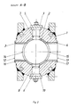
- Figures 1 and 2 show different views of a plug valve according to the invention.
- the left half of Figure 1 is shown as a vertical section through the plug valve and the right half of Figure 1 as a side view.
- the cock plug and the plates that close the openings for the installation of the plug pipe in the outer housing are shown in the manner of an exploded drawing.
- the faucet housing consists of a solid outer housing 1 made of austenitic steel and of a lining held in the outer housing 1, which is formed from three ceramic tubes, the plug tube 2 and the connecting tubes 3 and 4.
- the plug tube 2 is secured against rotation with respect to the outer housing 1 by two bolts 5 and 6 made of ceramic.
- the bolts 5 and 6 extend from the outer housing 1 into the wall of the plug tube 2.
- Seals 7 and 8 seal the bolts 5 and 6 against the outer housing 1. Plates 9 and 10, which are screwed to the outer housing 1, close the outer housing and hold the bolts 5 and 6 in place.
- the cock plug 11 is rotatably mounted in the plug pipe 2.
- the connecting pipes 3 and 4 connect the connections 12 and 13 to the plug pipe 2.
- the connecting pipes 3 and 4 have on one end face a recess 14 and 15, respectively, which is adapted to the cylindrical curvature of the outer surface of the plug pipe 2. These recesses can be made by a simple grinding process.
- the plug tube 2 is inserted and aligned so that the holes for receiving the bolts 5 and 6 are aligned.
- the bolts 5 and 6 are inserted and the outer housing 1 is closed by the plates 9 and 10.
- the connecting pipes 3 and 4 are inserted into the outer housing 1 by the connections 12 and 13 and secured by means of silicone compound 16 and 17 for transport.
- the connecting pipes 3 and 4 are through the to the Connections 12 and 13 connected pipes secured.
- the cock plug 11 is inserted into the plug pipe 2, and the plates 18 and 19 are screwed to the outer housing 1.
- the plates 18 and 19 close the outer housing 1 and prevent axial movement of the cock plug 11.
- the wall thickness of the ceramic tubes forming the lining of the outer housing is the same everywhere. The wall thickness can therefore be easily optimized for thermal shock resistance.
Landscapes
- Engineering & Computer Science (AREA)
- General Engineering & Computer Science (AREA)
- Mechanical Engineering (AREA)
- Valve Housings (AREA)
- Lift Valve (AREA)
- Sliding Valves (AREA)
Applications Claiming Priority (2)
| Application Number | Priority Date | Filing Date | Title |
|---|---|---|---|
| DE4003592A DE4003592A1 (de) | 1990-02-07 | 1990-02-07 | Kuekenhahn fuer abrasive medien |
| DE4003592 | 1990-02-07 |
Publications (3)
| Publication Number | Publication Date |
|---|---|
| EP0441283A2 true EP0441283A2 (fr) | 1991-08-14 |
| EP0441283A3 EP0441283A3 (en) | 1992-01-02 |
| EP0441283B1 EP0441283B1 (fr) | 1995-01-04 |
Family
ID=6399586
Family Applications (1)
| Application Number | Title | Priority Date | Filing Date |
|---|---|---|---|
| EP91101438A Expired - Lifetime EP0441283B1 (fr) | 1990-02-07 | 1991-02-04 | Robinet à tournant pour fluides abrasifs |
Country Status (2)
| Country | Link |
|---|---|
| EP (1) | EP0441283B1 (fr) |
| DE (2) | DE4003592A1 (fr) |
Cited By (1)
| Publication number | Priority date | Publication date | Assignee | Title |
|---|---|---|---|---|
| RU2192574C1 (ru) * | 2001-05-22 | 2002-11-10 | Агабабян Размик Енокович | Шаровой кран |
Family Cites Families (3)
| Publication number | Priority date | Publication date | Assignee | Title |
|---|---|---|---|---|
| DE277614C (fr) * | ||||
| DE567039C (de) * | 1932-12-27 | Ver Stahlwerke Akt Ges | Absperrvorrichtung, insbesondere Absperrhahn o. dgl. | |
| DE3642872A1 (de) * | 1986-12-16 | 1988-06-30 | Rolf Dipl Ing Daume | Kuekenhahn fuer aggressive medien |
-
1990
- 1990-02-07 DE DE4003592A patent/DE4003592A1/de active Granted
-
1991
- 1991-02-04 DE DE59104103T patent/DE59104103D1/de not_active Expired - Fee Related
- 1991-02-04 EP EP91101438A patent/EP0441283B1/fr not_active Expired - Lifetime
Cited By (1)
| Publication number | Priority date | Publication date | Assignee | Title |
|---|---|---|---|---|
| RU2192574C1 (ru) * | 2001-05-22 | 2002-11-10 | Агабабян Размик Енокович | Шаровой кран |
Also Published As
| Publication number | Publication date |
|---|---|
| EP0441283B1 (fr) | 1995-01-04 |
| EP0441283A3 (en) | 1992-01-02 |
| DE4003592A1 (de) | 1991-08-14 |
| DE59104103D1 (de) | 1995-02-16 |
| DE4003592C2 (fr) | 1992-11-19 |
Similar Documents
| Publication | Publication Date | Title |
|---|---|---|
| DE69717628T2 (de) | Mehrwegeventil für einen wärmetauscher | |
| DE3317061C2 (de) | Flanschverbindungsanordnung | |
| DE3632858C2 (fr) | ||
| DE202012101837U1 (de) | Vorrichtung zum Verbinden von Doppelmantelrohren (zweiteiliges Rohrkupplungsteil) | |
| DE1775140A1 (de) | Kugelschieberventil | |
| DE7800713U1 (de) | Metallrohr mit einer kunststoffauskleidung und einer halterung fuer ein loses bauteil | |
| DE60214775T2 (de) | Flanschglied mit einem ersten flanschende, das in einer radialrichtung mit einer konkaven endfläche ausgeführt ist, und einer flanschgliederumfassenden flanschverbindung | |
| EP0441283B1 (fr) | Robinet à tournant pour fluides abrasifs | |
| EP0295444B1 (fr) | Connexion de deux tuyaux d'une conduite pour fluides chauds | |
| EP3707435A1 (fr) | Chambre de combustion tubulaire munie d'un revêtement céramique | |
| EP0199360B1 (fr) | Vanne sphérique dans un corps revêtu d'une matière synthétique | |
| DE102014102290A1 (de) | Absperrarmatur mit drehbar angeordneter Absperrscheibe | |
| DE1002580B (de) | Schieber fuer Rohrleitungen, insbesondere fuer Heisswindleitungen von Hochofenanlagen | |
| EP2397709B1 (fr) | Articulation à billes et procédé de montage d'une articulation à billes | |
| DE3546086C2 (fr) | ||
| EP0318737B1 (fr) | Robinet à boisseau sphérique | |
| DE202008010465U1 (de) | Vorrichtung zur Isolierung eines Rohrleitungssystems | |
| DE4420461C2 (de) | Rohrkrümmer | |
| WO1995020738A1 (fr) | Corps d'appareil de robinetterie | |
| DE3872654T2 (de) | Ventil. | |
| DE7716118U1 (de) | Dehnungsausgleicher fuer rohrleitungen | |
| DE19802447A1 (de) | Sitzventil mit homogenem Ventilsitz und Verfahren zu seiner Herstellung | |
| AT232334B (de) | Schieberventil | |
| EP1433989B1 (fr) | Dispositif pour le transport de substances fluides à plusieurs phases | |
| DE8632731U1 (de) | Kugelhahn mit sinterkeramischen Sitzringen und sinterkeramischer Ventilkugel |
Legal Events
| Date | Code | Title | Description |
|---|---|---|---|
| PUAI | Public reference made under article 153(3) epc to a published international application that has entered the european phase |
Free format text: ORIGINAL CODE: 0009012 |
|
| AK | Designated contracting states |
Kind code of ref document: A2 Designated state(s): BE DE GB GR IT |
|
| PUAL | Search report despatched |
Free format text: ORIGINAL CODE: 0009013 |
|
| AK | Designated contracting states |
Kind code of ref document: A3 Designated state(s): BE DE GB GR IT |
|
| 17P | Request for examination filed |
Effective date: 19920211 |
|
| 17Q | First examination report despatched |
Effective date: 19930805 |
|
| GRAA | (expected) grant |
Free format text: ORIGINAL CODE: 0009210 |
|
| AK | Designated contracting states |
Kind code of ref document: B1 Designated state(s): BE DE GB GR IT |
|
| PG25 | Lapsed in a contracting state [announced via postgrant information from national office to epo] |
Ref country code: GR Free format text: LAPSE BECAUSE OF FAILURE TO SUBMIT A TRANSLATION OF THE DESCRIPTION OR TO PAY THE FEE WITHIN THE PRESCRIBED TIME-LIMIT Effective date: 19950104 Ref country code: BE Effective date: 19950104 |
|
| ITF | It: translation for a ep patent filed | ||
| REF | Corresponds to: |
Ref document number: 59104103 Country of ref document: DE Date of ref document: 19950216 |
|
| GBT | Gb: translation of ep patent filed (gb section 77(6)(a)/1977) |
Effective date: 19950327 |
|
| PLBE | No opposition filed within time limit |
Free format text: ORIGINAL CODE: 0009261 |
|
| STAA | Information on the status of an ep patent application or granted ep patent |
Free format text: STATUS: NO OPPOSITION FILED WITHIN TIME LIMIT |
|
| 26N | No opposition filed | ||
| PGFP | Annual fee paid to national office [announced via postgrant information from national office to epo] |
Ref country code: GB Payment date: 19980112 Year of fee payment: 8 |
|
| PG25 | Lapsed in a contracting state [announced via postgrant information from national office to epo] |
Ref country code: GB Free format text: LAPSE BECAUSE OF NON-PAYMENT OF DUE FEES Effective date: 19990204 |
|
| GBPC | Gb: european patent ceased through non-payment of renewal fee |
Effective date: 19990204 |
|
| PGFP | Annual fee paid to national office [announced via postgrant information from national office to epo] |
Ref country code: DE Payment date: 20010205 Year of fee payment: 11 |
|
| PG25 | Lapsed in a contracting state [announced via postgrant information from national office to epo] |
Ref country code: DE Free format text: LAPSE BECAUSE OF NON-PAYMENT OF DUE FEES Effective date: 20020903 |
|
| PG25 | Lapsed in a contracting state [announced via postgrant information from national office to epo] |
Ref country code: IT Free format text: LAPSE BECAUSE OF NON-PAYMENT OF DUE FEES;WARNING: LAPSES OF ITALIAN PATENTS WITH EFFECTIVE DATE BEFORE 2007 MAY HAVE OCCURRED AT ANY TIME BEFORE 2007. THE CORRECT EFFECTIVE DATE MAY BE DIFFERENT FROM THE ONE RECORDED. Effective date: 20050204 |