EP0437894A1 - Entrepôt à ajustage automatique - Google Patents
Entrepôt à ajustage automatique Download PDFInfo
- Publication number
- EP0437894A1 EP0437894A1 EP90203529A EP90203529A EP0437894A1 EP 0437894 A1 EP0437894 A1 EP 0437894A1 EP 90203529 A EP90203529 A EP 90203529A EP 90203529 A EP90203529 A EP 90203529A EP 0437894 A1 EP0437894 A1 EP 0437894A1
- Authority
- EP
- European Patent Office
- Prior art keywords
- warehouse
- brackets
- rod
- accordance
- sleeve
- Prior art date
- Legal status (The legal status is an assumption and is not a legal conclusion. Google has not performed a legal analysis and makes no representation as to the accuracy of the status listed.)
- Granted
Links
Images


Classifications
-
- B—PERFORMING OPERATIONS; TRANSPORTING
- B65—CONVEYING; PACKING; STORING; HANDLING THIN OR FILAMENTARY MATERIAL
- B65G—TRANSPORT OR STORAGE DEVICES, e.g. CONVEYORS FOR LOADING OR TIPPING, SHOP CONVEYOR SYSTEMS OR PNEUMATIC TUBE CONVEYORS
- B65G1/00—Storing articles, individually or in orderly arrangement, in warehouses or magazines
- B65G1/02—Storage devices
Definitions
- Warehouses of the type comprising a plurality of shelvings identifying compartments in which take their place elements to be stored in the form of packages such as cases, boxes, baskets, etc. supported by pallets and which are termed generally load units are known.
- Handling of the elements from and to the cells of the warehouse is performed by lift devices which traverse on tracks along the shelving and have fork means for raising and deposit of the pallets.
- the space between superposed shelves be just higher than the load unit so that the space between the top of a load unit and the shelf above be minimal. This can be secured easily if the load units are all of the same predetermined height or are in a limited quantity of standard height and in a foreseeable number so that the warehouse can be laid out in advance with appropriately spaced shelves.
- the warehouse must be sized to receive the highest load unit and consequently space utilization in the warehouse decreases as the number of load units of a height less than the maximum increases.
- the problem of sizing the compartments is particularly severe for example in warehouses for stocking and distributing seasonal products where the height of the load units changes as the products stored change.
- a known solution to the problem applicable to both cases is to provide on the side walls of the compartments small brackets, for support of auxiliary pallets and wider than those usually used with the load units, in such a manner as to provide shelving of an intermediate height by resting an auxiliary pallet on the small brackets.
- Such a solution results in the not negligible problem of having to foresee and store ready for use a number of auxiliary pallets equal to the expected maximum number of load units lower than the maximum height.
- enlargement of each compartment to allow insertion of load units on normal pallets without interference with the small support brackets considerably diminishes space utilization in the warehouse.
- the general object of the present invention is to obviate the above mentioned drawbacks by providing a warehouse with compartments for load units of varying height and handling means for loading and unloading thereof with compartment height adjustable rapidly to the height of the load unit while optimizing utilization of the warehouse volume.
- a warehouse of the type comprising shelving consisting of a plurality of risers connected by horizontal stringers to individualize an ordered plurality of compartments open at the front and arranged in rows and columns for receiving load units deposited and withdrawn therefrom by means of extractable forks born by a handling device moving along the shelving and positioning itself opposite the individual compartment characterized in that in each compartment are placed at intervals on the side walls pluralities of brackets facing each other in pairs, the brackets being rotatable on pivots by means of operating means acting on complementary elements on the brackets between a raised or rest position virtually parallel to the side wall of the compartment and a virtually horizontal lowered or supporting position, the distance between the facing brackets when they are in the raised position allowing a load unit to pass between them and when they are in the lowered position to rest thereon.
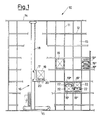
- a warehouse indicated generally by reference number 10 comprises shelving consisting of a plurality of risers 11 connected by horizontal stringers or brackets 12 to individualize a plurality of compartments 13 open at the front.
- a handling device 16 virtually of the known art having a lift 17 running along a vertical guide 18 for loading and unloading of load units 19, 19', 19" of varying height in the compartments by means of extractable forks 20.
- each compartment 13 there are at regular intervals movable side brackets 22 facing each other in pairs.
- each bracket 22 is joined by a pin 39 to the corresponding riser 11 separating two adjacent compartments 13 so as to be movable between a raised or rest position (shown in broken lines) with minimal projection into the compartment and a lowered or working position (shown in solid lines).
- Each bracket has an operating pin 23 directed toward the aisle where the device 16 passes. It is thus possible by engaging the pins 23 of the brackets to move them and thus create further divisions of the compartments 13. In this manner it is possible to optimize warehouse space utilization by determining the space between the stringers as the maximum height of the load unit storable in the warehouse and the space between the brackets and between the brackets and the stringers as the minimum height of the load unit acceptable in the warehouse.
- two pairs of brackets can be provided for each compartment so as to permit division thereof in three spaces for low load units 19", in two spaces for one medium-height load unit 19' and one low load unit 19", or in a single space for one high load unit 19.
- brackets in the working or rest position it is for example advantageous to fit the handling device 16 at the bottom as shown in FIG. 2 (otherwise known) with two powered arm devices 21 rotating axially and terminating with U elements 24 spaced virtually the distance of the pins 39 of facing brackets in a compartment.
- the U elements 24 can engage with the pins 23 of the facing brackets to raise or lower them.
- a load unit to be stored is a unit of maximum height 19 it is placed in a completely empty compartment 13 and the arms 21 do not enter into action. But if a load unit lower than the maximum is to be stored, for example of type 19' or type 19", it can occupy the empty upper space in a compartment already occupied by one or more load units of total height less than the maximum.
- the traversing device 16 need only bring the load unit near the empty space and engage the U parts of the arm 21 with the pins of the two movable brackets immediately above the upper unit already in the compartment, so as to bring the brackets into the support position and hence ready to receive the new load unit.
- the device 16 Upon withdrawal of a load unit from the warehouse, if it is resting on brackets 22 after the withdrawal operation the device 16 rotates with the arm 21 the corresponding brackets to the rest position so as to make the space available for a subsequent storage operation.
- Such an embodiment allows maximum flexibility since it is possible to store load units of various heights in an unforeseen number for each type and with the minimal space occupied.
- FIG. 4 shows a different embodiment applying the innovative principles claimed herewith to achieve positioning of the brackets 22 in a manner other than with 21 on the device 16.
- a warehouse virtually of the type shown in FIG. 1 and hence with movable brackets 22 having positioning pins 23 comprises in accordance with the different embodiment described below as shown in FIG. 4 rods 25 placed parallel along each riser 11 and bearing U elements 26 at regular intervals. Said rods run parallel to the risers and are rotatable around their own axis by means of mechanical movement units 27 and 28 operated for example by cranks 29 inserted in hexagonal engagement seats 30.
- the rods 25 terminate at the bottom with threaded ends to be screwed into threaded sleeves in turn screwed onto threaded pins 32 fixed to the base of the riser 11.
- the first movement unit unit 27 comprises a worm 33 coupled to a gear 34 in which the corresponding sleeve 31 slides.
- the sleeve 31 and gear 34 rotate integrally thanks to a guide 35 on the sleeve running in a corresponding seat in the gear 34.
- the second unit 28 comprises for each rod 25 a worm 36 coupled to a gear 37 in which runs the corresponding rod 25.
- the rod 25 and gear 37 rotate integrally thanks to a guide 38 on the rod running in a corresponding seat in the gear 37.
- the pitch of the U elements 26 along the rods 25 is different from the pitch of the brackets 22 along the risers 11 and such as to permit simultaneous engagement of the pins of all the brackets (either all raised or all lowered) occupying the same position in the compartments of an entire column of the warehouse without interfering with the other brackets of the compartments of said column.
- the brackets in each compartment form two shelves
- the U elements 26 will be two for each compartment and offset (as shown in fig. 4) in relation to the brackets so that when each U element 26 near for example the upper bracket of each compartment engages the corresponding movement unit pin 23 and moves to shift said brackets, the other U elements 26 near the lower brackets of each compartment do not interfere with the movement unit pins of said lower brackets. In this manner it is possible to simultaneously place in the desired position all the brackets of the same position on one side of the compartments of a column while leaving unchanged the position of the others.
- Said height can have for example with two pairs of brackets per compartment three different values for minimal waste of space and in each column of the warehouse there can be housed load units of two heights chosen among said three heights.
- each column depending on the movement unit of the brackets, can receive in each compartment a single load unit of maximum size, one medium-sized load unit 19' and one small load unit 19", or three small load units 19".
- the raising and rotation of the rod 25 can be achieved not only with a manual crank system but with a ratiomotor of the known art coaxial with the worms 33 and 36.
- the sleeve system described for raising the rods can be readily replaced by other known mechanisms. It would also be possible to provide a system similar to the one shown in FIG. 5 but with the sleeve lacking the lower threaded pins, losing the multiplying effect of the number of turns thereof for the purpose of axially moving the rods 25 but simplifying the mechanism since it is no longer necessary to provide the sleeves with the possibility of axial movement but only rotation.
Landscapes
- Engineering & Computer Science (AREA)
- Mechanical Engineering (AREA)
- Warehouses Or Storage Devices (AREA)
Applications Claiming Priority (2)
| Application Number | Priority Date | Filing Date | Title |
|---|---|---|---|
| IT01906390A IT1237950B (it) | 1990-01-15 | 1990-01-15 | Magazzino automatico adattabile |
| IT1906390 | 1990-01-15 |
Publications (2)
| Publication Number | Publication Date |
|---|---|
| EP0437894A1 true EP0437894A1 (fr) | 1991-07-24 |
| EP0437894B1 EP0437894B1 (fr) | 1993-12-08 |
Family
ID=11154227
Family Applications (1)
| Application Number | Title | Priority Date | Filing Date |
|---|---|---|---|
| EP90203529A Expired - Lifetime EP0437894B1 (fr) | 1990-01-15 | 1990-12-29 | Entrepôt à ajustage automatique |
Country Status (4)
| Country | Link |
|---|---|
| US (1) | US5149240A (fr) |
| EP (1) | EP0437894B1 (fr) |
| DE (1) | DE69005094D1 (fr) |
| IT (1) | IT1237950B (fr) |
Cited By (6)
| Publication number | Priority date | Publication date | Assignee | Title |
|---|---|---|---|---|
| DE19834378A1 (de) * | 1998-07-30 | 2000-02-10 | Wolf Hans Joachim | Vorrichtung zur Aufnahme mehrerer Gegenstände in übereinander liegenden Etagen |
| DE19859620A1 (de) * | 1998-12-23 | 2000-07-06 | Wolf Kunststoffe Gmbh | Vorrichtung zur Aufnahme mehrerer Gegenstände in übereinanderliegenden Etagen |
| EP1471015A2 (fr) * | 2003-04-22 | 2004-10-27 | WITRON Logistik & Informatik GmbH | Magazin à rayonnage à usage flexible |
| NL1023865C2 (nl) * | 2003-07-09 | 2005-01-11 | Logiqs Agro B V | Gevelwagen voor gebruik in een kas. |
| EP2824046A1 (fr) * | 2013-07-12 | 2015-01-14 | WITRON Logistik + Informatik GmbH | Rayonnage d'entrepôt avec des séparateurs verticaux amovibles pour l'utilisation de différentes tailles de supports |
| CN106628775A (zh) * | 2016-09-13 | 2017-05-10 | 许晶 | 一种移动式物品存取装置 |
Families Citing this family (16)
| Publication number | Priority date | Publication date | Assignee | Title |
|---|---|---|---|---|
| DE4205001C2 (de) * | 1992-02-19 | 1995-11-09 | Dambach Ind Anlagen | Regalbediengerät mit einem Horizontalförderer als Speichereinrichtung mit mehreren Speicherplätzen |
| GB9215324D0 (en) * | 1992-07-18 | 1992-09-02 | Adams Mark W | Improvements relating to goods storage |
| GB2284182B (en) * | 1992-07-18 | 1996-02-28 | Adams William M | Improvements relating to goods storage |
| US5540532A (en) * | 1993-11-12 | 1996-07-30 | Transact International, Inc. | Apparatus for marine cargo container handling and storage |
| DE4416103C2 (de) * | 1994-04-19 | 1999-01-07 | Bellheimer Metallwerk Gmbh | Hochregal |
| US6042321A (en) * | 1996-07-30 | 2000-03-28 | Westafalia Technologies, Inc. | Automated storage and retrieval system for palletless dairy cases |
| US6099230A (en) * | 1998-03-04 | 2000-08-08 | Beckman Coulter, Inc. | Automated labware storage system |
| EP0976667B1 (fr) | 1998-07-30 | 2004-03-03 | Wolf Kunststoffe GmbH | Dispositif destiné à recevoir des articles sur des niveaux superposés |
| DE10130984B4 (de) * | 2001-06-27 | 2004-03-25 | Knapp Logistik Automation Ges.M.B.H. | Regalbediengerät und Verfahren zum Bedienen eines Produktlagerregals insbesondere einer Kommissioniervorrichtung |
| DE10136354B4 (de) * | 2001-07-26 | 2010-06-17 | Knapp Ag | Verfahren und Anlage zum Kommissionieren mit einem Behälterregal und zugeordnetem Regalbediengerät |
| DE102004007412A1 (de) * | 2004-02-16 | 2005-09-01 | Knapp Logistik Automation Ges.M.B.H. | Verfahren und System zum Bedienen eines Regals vorzugsweise in einer Kommissionieranlage |
| ITMI20061341A1 (it) * | 2006-07-11 | 2008-01-12 | Fata Spa | Carrello di insilaggio shuttle e impianto per la movimentqzione e immagazzinamento di container |
| DE102007040863B4 (de) * | 2007-08-29 | 2010-07-29 | Hänel & Co. | Lagerregal mit Transportvorrichtung |
| DE102018100448A1 (de) * | 2018-01-10 | 2019-07-11 | Deutsche Post Ag | Sendungslager und Verfahren zum Übernehmen, Zwischenlagern und Ausgeben von Sendungen |
| DE102018103390A1 (de) | 2018-02-15 | 2019-08-22 | Dematic Gmbh | Vorrichtung und Verfahren zum Lagern von Waren mit einem Regal |
| DE102020213046A1 (de) | 2020-10-15 | 2022-04-21 | Gebhardt Fördertechnik GmbH | Lager- und Entnahmesystem sowie ein Lagerregal |
Citations (3)
| Publication number | Priority date | Publication date | Assignee | Title |
|---|---|---|---|---|
| US2675133A (en) * | 1951-07-16 | 1954-04-13 | Stora Kopparbergs Bergslags Ab | Stand for bar shaped material |
| DE1122000B (de) * | 1959-07-25 | 1962-01-11 | Demag Zug Gmbh | Geraet zum lueckenhaften Stapeln von flachen Guetern gleicher Groesse, insbesondere von Blechpaketen |
| DE2716632A1 (de) * | 1977-04-15 | 1978-10-19 | Dexion Gmbh | Programmierbare behaeltereinheit zur verwendung in einem organisationssystem fuer materialfluss und lagerung |
Family Cites Families (7)
| Publication number | Priority date | Publication date | Assignee | Title |
|---|---|---|---|---|
| DD40437A (fr) * | ||||
| US2957583A (en) * | 1958-05-12 | 1960-10-25 | John & Wm Burt Ltd | Racks for storing articles particularly cylinders |
| SU474484A2 (ru) * | 1967-10-30 | 1975-06-25 | Предприятие П/Я Р-6194 | Контейнер дл много русного хранени и перевозки железобетонных и других изделий |
| US3734312A (en) * | 1972-01-31 | 1973-05-22 | Hickinbotham Bros Ltd | Steel bar storage rack unit and cooperating lifting device |
| JPS604081B2 (ja) * | 1975-07-14 | 1985-02-01 | 三機工業株式会社 | ガイド板を兼用した商品支持レ−ルを具えた定量切出しラツク |
| JPS54136082A (en) * | 1978-04-10 | 1979-10-22 | Murata Mach Ltd | Cargo receiving and forwarding system for automatic storehouse |
| JPS62121109A (ja) * | 1985-11-18 | 1987-06-02 | Daifuku Co Ltd | ストツパ−付き棚を備えた自動倉庫 |
-
1990
- 1990-01-15 IT IT01906390A patent/IT1237950B/it active IP Right Grant
- 1990-12-29 EP EP90203529A patent/EP0437894B1/fr not_active Expired - Lifetime
- 1990-12-29 DE DE90203529T patent/DE69005094D1/de not_active Expired - Lifetime
-
1991
- 1991-01-14 US US07/640,813 patent/US5149240A/en not_active Expired - Fee Related
Patent Citations (3)
| Publication number | Priority date | Publication date | Assignee | Title |
|---|---|---|---|---|
| US2675133A (en) * | 1951-07-16 | 1954-04-13 | Stora Kopparbergs Bergslags Ab | Stand for bar shaped material |
| DE1122000B (de) * | 1959-07-25 | 1962-01-11 | Demag Zug Gmbh | Geraet zum lueckenhaften Stapeln von flachen Guetern gleicher Groesse, insbesondere von Blechpaketen |
| DE2716632A1 (de) * | 1977-04-15 | 1978-10-19 | Dexion Gmbh | Programmierbare behaeltereinheit zur verwendung in einem organisationssystem fuer materialfluss und lagerung |
Cited By (7)
| Publication number | Priority date | Publication date | Assignee | Title |
|---|---|---|---|---|
| DE19834378A1 (de) * | 1998-07-30 | 2000-02-10 | Wolf Hans Joachim | Vorrichtung zur Aufnahme mehrerer Gegenstände in übereinander liegenden Etagen |
| DE19859620A1 (de) * | 1998-12-23 | 2000-07-06 | Wolf Kunststoffe Gmbh | Vorrichtung zur Aufnahme mehrerer Gegenstände in übereinanderliegenden Etagen |
| EP1471015A2 (fr) * | 2003-04-22 | 2004-10-27 | WITRON Logistik & Informatik GmbH | Magazin à rayonnage à usage flexible |
| EP1471015A3 (fr) * | 2003-04-22 | 2005-12-14 | WITRON Logistik & Informatik GmbH | Magazin à rayonnage à usage flexible |
| NL1023865C2 (nl) * | 2003-07-09 | 2005-01-11 | Logiqs Agro B V | Gevelwagen voor gebruik in een kas. |
| EP2824046A1 (fr) * | 2013-07-12 | 2015-01-14 | WITRON Logistik + Informatik GmbH | Rayonnage d'entrepôt avec des séparateurs verticaux amovibles pour l'utilisation de différentes tailles de supports |
| CN106628775A (zh) * | 2016-09-13 | 2017-05-10 | 许晶 | 一种移动式物品存取装置 |
Also Published As
| Publication number | Publication date |
|---|---|
| IT9019063A0 (it) | 1990-01-15 |
| DE69005094D1 (de) | 1994-01-20 |
| US5149240A (en) | 1992-09-22 |
| IT1237950B (it) | 1993-06-19 |
| IT9019063A1 (it) | 1991-07-16 |
| EP0437894B1 (fr) | 1993-12-08 |
Similar Documents
| Publication | Publication Date | Title |
|---|---|---|
| EP0437894B1 (fr) | Entrepôt à ajustage automatique | |
| JP6491764B2 (ja) | 縦型物品保管・配分装置及び医薬品配分用機器 | |
| WO2009150684A1 (fr) | Dispositif et procédé utilisés pour prendre, manipuler et stocker des paquets dans un entrepôt automatisé | |
| EP2726385A1 (fr) | Système de stockage d'ascenseur vertical et procédé d'actionnement d'un ascenseur | |
| JPH07187331A (ja) | 自動倉庫における移載装置 | |
| ES2346798T3 (es) | Almacen automatico. | |
| US4872800A (en) | Unit goods storage | |
| EP3031037B1 (fr) | Entrepôt automatique | |
| EP1669308B1 (fr) | Procédé et dispositif pour chargement et déchargement des marchandises des rayonnages d'un stockage | |
| JPH07187330A (ja) | 自動倉庫における双方向移載装置 | |
| AU766179B2 (en) | Shelf storage facility | |
| JP3223709B2 (ja) | 自動倉庫における移載装置 | |
| EP3527506A1 (fr) | Système de gestion d'entrepôts multiniveaux et entrepôt multiniveaux comprenant un tel système de gestion | |
| US3844423A (en) | Pallet accumulator | |
| US6619902B1 (en) | Automated storage and retrieval system and indexing/insertion extraction mechanism therefor | |
| JP3173266B2 (ja) | 自動倉庫における移載装置 | |
| US6729482B1 (en) | Automated storage and retrieval system | |
| KR20230074264A (ko) | 컨테이너 보관 및 인출 시스템 | |
| US6347713B1 (en) | Multilevel modular storage system with modules sliding horizontally in both directions | |
| EP0574732B1 (fr) | Magasin pour le stockage d'objets | |
| EP2452899B1 (fr) | Dispositif de manipulation automatique d'unités de chargement dans des magasins à rayonnages | |
| JPS6240963Y2 (fr) | ||
| DE3408941A1 (de) | Vorrichtung zum lagern von gebinden mit automatischer ein- und auslagerung bzw. umlagerung | |
| US20240010428A1 (en) | Systems and methods for providing mobile shuttle load handling systems | |
| KR830000698B1 (ko) | 자동판매기의 상품 선반 |
Legal Events
| Date | Code | Title | Description |
|---|---|---|---|
| PUAI | Public reference made under article 153(3) epc to a published international application that has entered the european phase |
Free format text: ORIGINAL CODE: 0009012 |
|
| AK | Designated contracting states |
Kind code of ref document: A1 Designated state(s): BE DE ES FR GB |
|
| 17P | Request for examination filed |
Effective date: 19911220 |
|
| 17Q | First examination report despatched |
Effective date: 19920811 |
|
| GRAA | (expected) grant |
Free format text: ORIGINAL CODE: 0009210 |
|
| AK | Designated contracting states |
Kind code of ref document: B1 Designated state(s): BE DE ES FR GB |
|
| PG25 | Lapsed in a contracting state [announced via postgrant information from national office to epo] |
Ref country code: FR Effective date: 19931208 Ref country code: ES Free format text: THE PATENT HAS BEEN ANNULLED BY A DECISION OF A NATIONAL AUTHORITY Effective date: 19931208 Ref country code: DE Effective date: 19931208 Ref country code: BE Effective date: 19931208 |
|
| REF | Corresponds to: |
Ref document number: 69005094 Country of ref document: DE Date of ref document: 19940120 |
|
| EN | Fr: translation not filed | ||
| PLBE | No opposition filed within time limit |
Free format text: ORIGINAL CODE: 0009261 |
|
| STAA | Information on the status of an ep patent application or granted ep patent |
Free format text: STATUS: NO OPPOSITION FILED WITHIN TIME LIMIT |
|
| 26N | No opposition filed | ||
| PGFP | Annual fee paid to national office [announced via postgrant information from national office to epo] |
Ref country code: GB Payment date: 19941220 Year of fee payment: 5 |
|
| PG25 | Lapsed in a contracting state [announced via postgrant information from national office to epo] |
Ref country code: GB Effective date: 19951229 |
|
| GBPC | Gb: european patent ceased through non-payment of renewal fee |
Effective date: 19951229 |