EP0437865B1 - Storage device for reversibly storing digital data on a multitrack storage medium, a decoding device, an information reproducing apparatus for use with such storage medium, and a unitary storage medium for use with such storage device, decoding device and/or information reproducing device - Google Patents
Storage device for reversibly storing digital data on a multitrack storage medium, a decoding device, an information reproducing apparatus for use with such storage medium, and a unitary storage medium for use with such storage device, decoding device and/or information reproducing device Download PDFInfo
- Publication number
- EP0437865B1 EP0437865B1 EP90200128A EP90200128A EP0437865B1 EP 0437865 B1 EP0437865 B1 EP 0437865B1 EP 90200128 A EP90200128 A EP 90200128A EP 90200128 A EP90200128 A EP 90200128A EP 0437865 B1 EP0437865 B1 EP 0437865B1
- Authority
- EP
- European Patent Office
- Prior art keywords
- tracks
- code
- tape
- segment
- symbols
- Prior art date
- Legal status (The legal status is an assumption and is not a legal conclusion. Google has not performed a legal analysis and makes no representation as to the accuracy of the status listed.)
- Expired - Lifetime
Links
Images


Classifications
-
- G—PHYSICS
- G11—INFORMATION STORAGE
- G11B—INFORMATION STORAGE BASED ON RELATIVE MOVEMENT BETWEEN RECORD CARRIER AND TRANSDUCER
- G11B20/00—Signal processing not specific to the method of recording or reproducing; Circuits therefor
- G11B20/10—Digital recording or reproducing
- G11B20/18—Error detection or correction; Testing, e.g. of drop-outs
- G11B20/1806—Pulse code modulation systems for audio signals
- G11B20/1809—Pulse code modulation systems for audio signals by interleaving
Definitions
- the invention relates to a storage device for storing digital data on a multitrack storage medium.
- the medium may be a magnetic cassette tape that has a plurality of parallel tracks.
- the "tracks" could be successive revolutions of what is effectively a spiral on a disk, such as an optical recording disk.
- Storage of digital data is notoriously sensitive against mutilation, that may be operative both on the level of any arbitrary bit, or be represented by long strings of bits along a particular track that have a high error probability.
- BCH codes over finite fields have proven advantageous error protection vehicles, in particular Reed-Solomon codes defined for multi-symbol words, each symbol being an 8-bit element of a Galois field, the codes being systematic on the symbol level. The ordinary-skilled technician could do away with various ones of these restrictions without deviating from the general concept of the invention.
- the invention relates to a storage device for storing digital data on a storage medium with a first plurality of substantially uniform and contiguous storage tracks, under execution of an error protection encoding operation by means of a block code consisting of Cl-code words, in a first direction and of C2-code words in a second direction, said device having first encoding means for said first code to generate error protected C1 code words each assigned to a particular single track, second encoding means for said second code to generate error protected C2 code words each assigned to all of said first plurality of tracks, and means for separating the symbols of a code words.
- the present invention has considered the advantageous properties of a classical product code, both in terms of error protectivity and in terms of decoding effort, for realizing an appropriate degree of protection at a reasonable complexity of encoding and decoding and realizing such protection in a regular format.
- the invention provides such device, characterized in that all user symbols and redundant symbols of the C1 code words and C2 code words have a uniform multibit size, in that said block code is a product code, in that each C2 code word has a number of symbols that is an exact multiplicity of said first plurality of tracks, and which symbols are assigned to said first plurality of tracks according to a multiply recurrent and uniform cycle along their particular C2 code words, and in that said device has physical disposition means for disposing each C2 code word so that among symbols of the latter C2 code word spacings between physically neighbouring symbols are substantially uniform in size and have non-zero components both along said tracks and across said tracks.
- the storage format so attained offers robustness against row errors that afflict a large fraction of the data on any single track and column errors, that could afflict a plurality of code symbols that in principle are written simultaneously, if writing skew is ignored. Furthermore, robustness against drop-out patches of the medium is so realized.
- the cross-track component derives from a uniform cross track jump between successive symbols of said C2 code word which is an integer number of tracks modulo said first plurality, said integer number also being relatively prime to said first plurality. This allows for easy address calculations.
- the along-track component derives from a uniform-along-track jump between successive symbols of said C2 code word.
- write means are provided for magnetically writing in parallel tracks that are tape tracks.
- fine quality tape allows so for high-density storage and high-rate transfer.
- the write means interface to the plurality of tracks as mutually contiguous tracks. This makes relative positioning superfluous and further raises attainable storage density.
- the first plurality of tracks is disposed on half of said tape and within said first plurality of tracks an outer edge track on said tape is fully filled with parity symbols that each pertain to an associated C2 code word.
- Outer tracks are slightly more susceptible to mutilation and in consequence, overall susceptibility is diminished.
- each track has a sequence of blocks, each block containing a uniform integer number of C1 code words, and wherein said integer number is 2 and within any block its C1 code words are 2-interleaved. This raises the uniformity of the storage organization.
- a second plurality of blocks is contained in a tape segment of uniform size
- a third plurality of tape segments is contained in a tape frame of second uniform size, said tape segments and tape frames being mutually synchronous among said first plurality of tracks, and any said C2 code word being fully contained in a single tape frame.
- mutually synchronous blocks among said tracks constitute a slice, and wherein each C2 code word is uniformly distributed over all slices of a frame. This further improves uniformity.
- a RAM encoding memory accommodating storage of a fourth plurality of tape segments, to wit an input RAM segment for therein receiving user data of an intended tape segment, a further RAM segment series for therein storing user data of a corresponding set of intended tape segments and for therein encoding associated C1 and C2 code words and an output RAM segment for therefrom outputting a fully encoded tape segment.
- the C2 code words may be distributed over a plurality of RAM segments, and C1 code words over a single segment, the total storage capacity required is only two RAM segments more than the number covered by the extension of the C2 code words.
- the first plurality is equal to 8. This is a good trade-off between high transfer rate and moderate apparatus complexity.
- said C1 code is a (24, 20, 5) code and said C2 code is a (32, 26, 7) code.
- These codes in particular as combined in a product code, provide immunity against a wide range of errors. Nevertheless, the mathematical complexity of executing correction and/or detection of errors remains simple. In particular, odd-distance codes were found to team up better than even-distance codes, even if the codes now have rather different distances.
- each frame comprises 384 C2 code words. In this, simple organization and large capacity of storage are balanced.
- the non-zero component across said tracks derives from a jump +5 modulo said first plurality. This allows for simple address processing.
- the medium is a reversible storage medium.
- a reversible storage medium In addition to magnetics, also state of the art optical storage would be usefull.
- the device would comprise reception means for an analog audio signal, analog to digital conversion means fed by said reception means for by A/D conversion providing at least a substantial part of said digital data for subsequent encoding by said product code.
- Direct audio to coded-data conversion provides an effective countermeasure to interference by external disturbances.
- such reader device comprises a multisegment RAM memory, filling means for sequentially filling a predetermined second plurality of RAM segments with data from said real or emulated storage medium, wherein any C1 code word is exclusively assigned to one single RAM segment, and any C2 code word is exclusively assigned to a single one multisegment RAM frame, in that any C2 code word runs with a uniform row jump and uniform column jump through said RAM frame modulo the dimensions of said RAM frame. This represents a relatively low requirement for storage capacity.
- each memory segment comprising its multisegment RAM memory, wherein each RAM segment accommodates a uniform third plurality of C1 code words that is uniformly distributed among said first plurality of tracks as relating exclusively to a single medium segment, so that any storage medium segment fits 1:1 on a RAM segment, and further provided with first decode means for upon filling of each memory segment directly activating decoding of any C1 code word available in said memory segment. Fast activation of the decoding diminishes the time lag between reading and reproducing of stored information.
- said apparatus upon storage said C2 code words cross intra-memory segment boundaries up to a third plurality of memory segments but no other intra-memory segment boundaries, and said apparatus having second decoding means for after storing of said C2 code words in said third plurality of memory segments and decoding by said first decode means activating decoding said C2 code words.
- Such time lag by means of this stratagem is kept low as well.
- said memory accommodates in addition to said third plurality of memory segments, one further input segment for inputting data of one storage medium segment and one second further segment for outputting data of one already decoded storage medium segment.
- a four-sgement frame now only requires a six-segment memory.
- the invention also relates to an information reproducing device and containing a decoding device as recited supra, comprising holding/driving means for said storage medium in the form of a magnetic tape, head means for time-sequentially accessing a stretch of locations on said tape, and audio reproduction means fed by said decoding device.
- a decoding device as recited supra, comprising holding/driving means for said storage medium in the form of a magnetic tape, head means for time-sequentially accessing a stretch of locations on said tape, and audio reproduction means fed by said decoding device.
- Such device would represent a price-effective consumer entertainment apparatus for general use.
- the decoder part thereof could well be contained in a single-chip embodiment.
- the invention also relates to a magnetic tape for use with a decoding device as described supra, and comprising said first plurality of substantially uniform storage tracks, said tracks comprising a storage frame which is equally distributed over said parallel tracks that are single-sidedly disposed on one half of said a magnetic tape, said frame being protected by a symbol-correcting block product code as represented by C1 words and C2 words, each C1 word being disposed within exactly one of said tracks, each C2 word being disposed over all of said tracks in that said C2 word has a number of symbols that is an exact multiplicity of said first plurality, and which symbols are assigned to said plurality of tracks according to a multiply recurrent and uniform cycle along their particular C2 code words and in that physical spacing among neigbhouring symbols of the latter C2 word is substantially uniform and has non-zero components both along said tracks and across said tracks.
- the invention also relates to a storage medium as described supra and contained in a cassette that interfaces to an apparatus also described hereinbefore. Such cassette would still further rise the physical integrity of the storage.
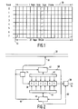
- Figure 1 exemplifies the main data allocation, that is user data plus associated redundancy data. Further, in this respect, Table 1 formalizes the mapping of user data onto the tape.
- the user bytes (or symbols) are numbered sequentially. Their internal organization is not considered; they could, however, derive from digitized single-channel or double-channel audio, video, or other.
- Each byte D has three indexes t, b, i, namely track number t in [0,7], tape block number b in [0,31], and symbol number within a block in [0,47].
- the number of user main data bytes in a tape frame is 8192. The placement of these bytes according to their placement number u in [0,8191] is found with the formulae of Table 1.
- each tape frame is divided into 32 consecutive tape slices shown as columns.
- Each tape slice contains 8 tape blocks, that is one tape block for each track.
- one tape frame is divided into four frame segments that each contain 8 consecutive slices of the tape frame in question. These frame segments have not been indicated in the Figure.
- One tape block 22 corresponds to 408 unmodulated main data bits, that are modulated into 510 channel bits. For brevity, the modulating into channel bits has not been detailed further and the consideration hereinafter only applies to the unmodulated bits.
- Each tape block consists of a sync-pattern of 10 bits, a number-indication symbol of 8 unmodulated bits, and a parity symbol of 8 unmodulated bits which leaves 48 body symbols.
- FIG. 2 is a block diagram of a decoder apparatus embodiment.
- the tape 30 is read simultaneously in eight parallel tracks by tape access mechanism 32 which also executes the demodulating.
- Block 34 driven by synchronization mechanism not shown, counts off bytes, segments, and frames.
- RAM 36 comprises six RAM segments or pages that are numbered 0-5. It is fed by counting block 34 that provides write addresses by successive incrementation and also gates the data to RAM 36.
- counting block 38 gates data read out from RAM 36 unto user line 54 and provides read addresses by successive incrementation. In this way RAM 36 is a first-in-first-out buffer with respect to the user data.
- block 42 is the C1 decoder that bidirectionally accesses RAM 36 via its access facility 40.
- block 46 is the C2 decoder that bidirectionally accesses RAM 36 via its own access facility 44.
- Figure 3 schematically shows the segment-wise accessing of RAM 36 by write counter/gate mechanism 34. Inasmuch as time goes from left to right in the Figure, all six RAM-pages are filled or overwritten in cyclical sequence. The physical disposition of the segments in the RAM structure is of no consequence to the decoding organization.
- row 62 shows the decoding operation by C1 decoder 42. Decoder 42 receives a synchronizing signal from counter/gate mechanism 34 on line 48 and in consequence, knows the instant on which a complete segment has been filled in RAM 36 and also its address (range).
- the C2 decoding can be effected directly on the four segments after the last thereof has been received, provided that the C1 decoder has finished its operation (regardless of whether the correction has been successfull or not).
- small arrows indicate the frame boundaries.
- the C2 decoding is effected during a single segment interval following the complete reception of the frame in question.
- C2 decoder 46 is also synchronized by counter/gate 35 via line 48, and moreover, receives "ready" signal from C1 decoder 42 on line 50.
- line 52 may carry a "free" signal to output counter/gate 38. Alternatively, the latter is unconditionally synchronized via a signal on line 48.
- Row 66 shows that the operation of C2 decoder 46 is followed by the read access on four consecutive RAM segments that had been treated during the most recent operation of C2 decoder 46.
- the four tape segments received through interval 68 are outputted through interval 70.
- the whole arrangement of Figure 2 functions as an error correction FIFO with an incurred delay of five tape segment intervals. It is clear that six RAM segments are necessary and sufficient for the storage. If the C2 decoding were to take more time, for example two or three tape segment intervals, the storage requirements would amount to seven or eight RAM segments, respectively.
- RAM 36 has a four-port facility.
- decoders 42, 46 function alternatively, their respective operations may be mapped on a single hardware facility that is suitably programmed.
- writing by counter/gate element 34 reading by counter/gate element 38 and decoding by decoders 42, 46 never take place on the same RAM segment, on a segment level RAM 36 may be limited to a one-port facility.
- the set-up described above may comprise a reset functionality not shown which is activated, for example, upon recognition of the correct accessing of the first frame. This may be signalled by the first frame start encountered after block headers have begun to show up correctly. Furthermore, as described infra, the C1 code words are confined to one respective block only. In consequence this could be used to a slight further acceleration in that C1 decoding would start directly after the associated block. Estimation of the operation has revealed that additional cost of a more complicated control arrangement would not outweigh additional benefits.
- the redundancy generating is somewhat easier than decoding, so elements 42, 46 could be simplified. For example, no feed-back operation is necessary, wherein an unexpected outcome, such as an uncorrectable error in a C2 word, would necessitate other measures to be taken.
- the combined symbol correcting codes yield a product code system. This means that for encoding the time sequence of encoding the two codes is inconsequential: after the user data of a whole segment has arrived in RAM, either the C1 code words could have their redundancy calculated first, or, alternatively, first the C2 code words.
- the user data of a product code can be visualized as a matrix.
- the redundancy consists of three parts:
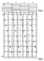
- Figure 4 shows the data mapping on the tape, in particular one frame with its four tape segments A. . D, each tape segment having respective equal-sized fractions thereof disposed on each of eight tracks 0..7. Within each tape segment, two respective track segments have been shown hatched in such way that on each track one track segment has been shown hatched.
- Figure 5 shows the data mapping of the same tape frame in four RAM segments A0, B0, C0, D0 wherein the total content of one tape segment has been mapped exclusively on the like-indicated RAM segment, such as A-to-A0.
- the two remaining RAM segments according to Figures 2, 3, may left out of consideration with respect to the tape frame in question, because they do not contribute to the product code of the frame now under consideration.
- the vertical scale in Figure 4 tracks
- the horizontal scale in Figure 5 memory columns within each respective RAM segment as shown at the lower edge
- the horizontal scale in each tape segment of Figure 4 has been expanded vertically in Figure 5 for better clarity, as represented by the larger area of Figure 5 as compared to that of Figure 4.
- Figure 5 shows the mapping of each of the hatched track segments of Figure 4 on a column of the corresponding RAM segment, while retaining the orientation of the hatching.
- the mapping is one to one, the column number with in the RAM segment being equal to (t ⁇ 5)mod 8 + 8.
- the column number in the complete RAM is then found by adding 8 times the segment number, which for RAM segments A0, B0, C0, D0 is 0, 1, 2, 3, respectively.
- the mapping in the other direction is the same inasmuch as track 1 is mapped on column 5, within RAM segment B0.
- each block of 408 unmodulated bits, has two (2) C1 code words of 24 symbols each (and three other symbols, not relevant here).
- the two code words have a 2-interleave in that odd-numbered symbols belong to one code word and even-numbered symbols belong to the other.
- This also applies to the eight redundant symbols within each block, which are the last symbols of the block (right hand most in Figure 1) on the tape. In consequence, in RAM they fill the lowest eight rows of each set of 48 rows.
- Figure 5 shows one particular code word that starts with the symbol on row 0, column 0. Thereafter, the row jump is 48 and the column jump is one. In consequence, each next symbol relates to a different track. Further, each next symbol jumps by one block in the direction of the tape track. The cross track jump is plus (+) five tracks modulo 8 (without carry or borrow). For the one code word in question, all symbols have been highlighted in Figure 5 as dark squares. Transposition to other code words is effected by shifting all symbols over a uniform number of rows (with rotation between the upper and lower edges) and/or over a second uniform number of columns (with rotation between the left and right edges).
- Figure 6 shows the disposition of the first 18 symbols of the C2 code word highlighted in Figure 5, each cross now representing one symbol of the block of 48 symbols in question. Each next symbol now is in a next tape block column, and shifted over five tape tracks (mod 8) without carry or borrow.
- the position of the respective symbols within their associated block has not been shown.
- envisaged tape speed is 4.76 cms/sec at a bit rate of 96 kilobits per second. This results in a bit length of 0.495 micron. Track pitch was intended as 195 microns, which means that in such longitudinal recording the bit area is substantially shorter than wide.
- each tape block has 510 channel bits which gives a block length of 253 microns, which means that the area covered by a block is 253x195 microns which is considered approximately square.
- Figure 6A shows the center-to-center distances between neighbouring symbols of a C2 code word in the three possible relative dispositions. The symbols are shown as vertical bars within their blocks of which only the corners have been indicated by dots.
- the relative distances of 640, 780 microns relate as 1:1.22. Other relationships, such as up to 1:1.3 or even up to 1:1.4 could be considered as yielding a substantially uniform distance between nearest neighbours.
- the Figure takes into account that the code symbols within their respective blocks have identical positions.
- the uniform distance implies a good robustness of the code against scratches and other burst-type errors.
- a circle encompassing such six symbols in Figure 6 at 100% erasure therein would not cause breakdown of the error correction capability.
- this would correspond to the width of some six blocks on a row, which is 1,5 millimeter, which is considered sufficient for almost every purpose.
- track number 0 has been filled completely with redundant symbols of the C2 code; in the highlighted code word of Figure 5, this implies all code symbols (4) on the top row of the RAM memory, having symbol numbers 0, 8, 16, 24.
- the other parity symbols have the following rank: for even-numbered C2 code words (0, 2 .. 382) they are positioned at symbols 7,23. For odd-numbered C2 code words (1, 3 .. 383) the further redundant words are positioned at symbols 15,31. This means that all those other redundant symbols are mapped on track 3, which is now 50% covered with parity symbols.
- Block 100 is a source for analog audio signals. This may be, for example an audio record player, a loud-speaker, or a naturally occurring audio source, such as an orchestra.
- Block 102 represents an audio input to the system, such as a microphone or wire connection, plus its associated audio amplification, filtering etcetera.
- Block 104 represents the analog to digital conversion of audio samples taken from element 102.
- Block 106 represents the encoding as referred to earlier, complete with digital processing provisions, encoding RAM.
- Block 108 represents a formatting element for the encoded data, thereby generating the tape segments. These can be outputted in various different ways, such as in parallel by 8 mode.
- Block 110 represents the broadcast amplifier, broadcast medium and broadcast receiver combined. Alternatively, such elements may be adapted for cable or wave-guide use. Still more alternatively, magnetic head for writing and reading, respectively inclusive of the magnetomotoric storage on digital audio tape.
- the audio tape, or, alternatively, audio disk may be housed in a cassette of suitable box-like or envelope-like dimensions, shaped according to protective needs, storage requirements, accessibility and commercial promotivity. If required, read head(s) and write head(s) may be integrated or even combined into a single head or head set.
- Block 112 represents the decoder device together with decoding RAM.
- Block 114 represents an output mechanism, comprising D/A conversion, de-interleaving, amplification and loudspeaking as far as required.
- Block 116 represents a driving mechanism at the production side of the encoded data, for example as a tape drive.
- Block 118 represents a likewise organized driving mechanism at the reception side for the encoded data.
- the driving mechanisms could be integrated to a single driving mechanism.
- various constructional and organizational details have been foregone. It should be noted that the production side operates as if the reception side were present indeed, and as such emulates presence of the receiving side: it operates as if the receiving side were present. Likewise, the receiving side emulates the transmission side: it operates as if the transmission side were present.
Landscapes
- Engineering & Computer Science (AREA)
- Multimedia (AREA)
- Signal Processing (AREA)
- Signal Processing For Digital Recording And Reproducing (AREA)
- Measuring Or Testing Involving Enzymes Or Micro-Organisms (AREA)
Priority Applications (22)
| Application Number | Priority Date | Filing Date | Title |
|---|---|---|---|
| DE69030490T DE69030490T2 (de) | 1990-01-18 | 1990-01-18 | Aufzeichnungsvorrichtung zum umkehrbaren Speichern von digitalen Daten auf einem Mehrspuren-Aufzeichnungsträger, Dekodiervorrichtung, Informationswiedergabegerät für die Verwendung mit einem solchen Aufzeichnungsträger und Aufzeichnungsträger für die Verwendung mit einer solchen Aufzeichnungsvorrichtung, mit einer solchen Dekodiervorrichtung und/oder mit einem solchen Informationswiedergabegerät |
| ES90200128T ES2103719T3 (es) | 1990-01-18 | 1990-01-18 | Dispositivo de almacenamiento reversible de datos digitales sobre un medio multipista, dispositivo descodificador aparato de reproduccion de informacion para utilizar con dicho medio, y soporte de almacenamiento para utilizar con dicho dispositivo de almacenamiento, con dicho |
| EP90200128A EP0437865B1 (en) | 1990-01-18 | 1990-01-18 | Storage device for reversibly storing digital data on a multitrack storage medium, a decoding device, an information reproducing apparatus for use with such storage medium, and a unitary storage medium for use with such storage device, decoding device and/or information reproducing device |
| AT90200128T ATE151908T1 (de) | 1990-01-18 | 1990-01-18 | Aufzeichnungsvorrichtung zum umkehrbaren speichern von digitalen daten auf einem mehrspuren-aufzeichnungsträger, dekodiervorrichtung, informationswiedergabegerät für die verwendung mit einem solchen aufzeichnungsträger und aufzeichnungsträger für die verwendung mit einer solchen aufzeichnungsvorrichtung, mit einer solchen dekodiervorrichtung und/oder mit einem solchen informationswiedergabegerät |
| BR919100148A BR9100148A (pt) | 1990-01-18 | 1991-01-15 | Dispositivo de armazenamento para armazenar dados digitais,dispositivo emulador,dispositivo decodificador,aparelho reprodutor de informacoes,e suporte de armazenamento unitario |
| MYPI91000062A MY105327A (en) | 1990-01-18 | 1991-01-15 | A storage system for reversibly storing digital, data on a multitrack medium |
| SU914894347A RU2037888C1 (ru) | 1990-01-18 | 1991-01-15 | Способ записи цифровой информации на носителе и устройство для воспроизведения цифровой информации с носителя записи |
| HU91117A HUT61624A (en) | 1990-01-18 | 1991-01-15 | Storage unit for storing digital information on multiband datacarrier with error-correcting coding, as well as decoder and datacarrier with uniform code formatum |
| CN91100376A CN1038163C (zh) | 1990-01-18 | 1991-01-15 | 多道存储媒体的双向存储、译码、重放装置及其所用单式媒体 |
| PL91288706A PL165838B1 (pl) | 1990-01-18 | 1991-01-15 | Urzadzenie i sposób odczytywania zapamietanych danych cyfrowych PL PL |
| CA002034200A CA2034200A1 (en) | 1990-01-18 | 1991-01-15 | Storage device for reversibly storing digital data on a multitrack storage medium, a decoding device, an information reproducing apparatus for use with such storage medium, and a unitary storage medium for use with such storage device, decoding device and/or information reproducing device |
| PT96484A PT96484A (pt) | 1990-01-18 | 1991-01-15 | Dispositivo de armazenamento reversivel para dados digitais |
| FI910203A FI910203A (fi) | 1990-01-18 | 1991-01-15 | Minnesanordning foer reversibel lagring av digital information pao ett flerspaorsminnesmedel, avkodningsanordning, informationsanvisningsanordning foer anvaendning med en saodan minnesanordning, samt minnesmedel foer anvaendning med saodan minnesanordning, avkodningsanordning och/eller informationsanvisning |
| CS9180A CS8091A2 (en) | 1990-01-18 | 1991-01-15 | Device for digital data storage on multitrack memory medium, for decoding and information reproduction and unit memory medium for application with such a device |
| AU69393/91A AU643246B2 (en) | 1990-01-18 | 1991-01-16 | Storage device for reversibly storing digital data on a multirack storage medium, a decoding device, an information reproducing apparatus for use with such storage medium, and a unitary storage medium for use with such storage device, decoding device and/or information reproducing device |
| AR91318871A AR246633A1 (es) | 1990-01-18 | 1991-01-17 | Un dispositivo de almacenamiento. |
| KR1019910000679A KR100209865B1 (ko) | 1990-01-18 | 1991-01-17 | 디지탈 기억용 기억장치 |
| YU8191A YU8191A (sh) | 1990-01-18 | 1991-01-18 | Memorijski uredjaj za reverzibilno memorisanje digitalnih podataka na višestazni memorijski medijum |
| JP3019437A JPH04212762A (ja) | 1990-01-18 | 1991-01-18 | 複数トラック記憶媒体上にデジタルデータを可逆的に記憶する記憶装置、デコード装置、そのような記憶媒体と共に使用する情報再生装置、及びそのような記憶装置、デコード装置及び/又は情報再生装置と共に使用する一体的記憶媒体 |
| US08/197,020 US5467360A (en) | 1990-01-18 | 1994-02-15 | Storage device for reversibly storing digital data on a multitrack storage medium, a decoding device, an information reproducing apparatus for use with a storage medium, and a unitary storage medium for use with such a storage device decoding device and/o |
| US08/419,483 US5592497A (en) | 1990-01-18 | 1995-04-10 | Multitrack record carrier having digital data reversibly stored thereon as error protected product codewords |
| HK98105222A HK1006202A1 (en) | 1990-01-18 | 1998-06-12 | Storage device for reversibly storing digital data on a multitrack storage medium a decoding device an information reproducing apparatus for use with such storage medium and a unitary storage medium for use with such storage device decoding device and/or information reproducing device |
Applications Claiming Priority (2)
| Application Number | Priority Date | Filing Date | Title |
|---|---|---|---|
| EP90200128A EP0437865B1 (en) | 1990-01-18 | 1990-01-18 | Storage device for reversibly storing digital data on a multitrack storage medium, a decoding device, an information reproducing apparatus for use with such storage medium, and a unitary storage medium for use with such storage device, decoding device and/or information reproducing device |
| HK98105222A HK1006202A1 (en) | 1990-01-18 | 1998-06-12 | Storage device for reversibly storing digital data on a multitrack storage medium a decoding device an information reproducing apparatus for use with such storage medium and a unitary storage medium for use with such storage device decoding device and/or information reproducing device |
Publications (2)
| Publication Number | Publication Date |
|---|---|
| EP0437865A1 EP0437865A1 (en) | 1991-07-24 |
| EP0437865B1 true EP0437865B1 (en) | 1997-04-16 |
Family
ID=26125718
Family Applications (1)
| Application Number | Title | Priority Date | Filing Date |
|---|---|---|---|
| EP90200128A Expired - Lifetime EP0437865B1 (en) | 1990-01-18 | 1990-01-18 | Storage device for reversibly storing digital data on a multitrack storage medium, a decoding device, an information reproducing apparatus for use with such storage medium, and a unitary storage medium for use with such storage device, decoding device and/or information reproducing device |
Country Status (15)
| Country | Link |
|---|---|
| US (2) | US5467360A (es) |
| EP (1) | EP0437865B1 (es) |
| JP (1) | JPH04212762A (es) |
| CN (1) | CN1038163C (es) |
| AT (1) | ATE151908T1 (es) |
| AU (1) | AU643246B2 (es) |
| CA (1) | CA2034200A1 (es) |
| CS (1) | CS8091A2 (es) |
| DE (1) | DE69030490T2 (es) |
| ES (1) | ES2103719T3 (es) |
| FI (1) | FI910203A (es) |
| HK (1) | HK1006202A1 (es) |
| PL (1) | PL165838B1 (es) |
| PT (1) | PT96484A (es) |
| RU (1) | RU2037888C1 (es) |
Families Citing this family (47)
| Publication number | Priority date | Publication date | Assignee | Title |
|---|---|---|---|---|
| ES2103719T3 (es) * | 1990-01-18 | 1997-10-01 | Philips Electronics Nv | Dispositivo de almacenamiento reversible de datos digitales sobre un medio multipista, dispositivo descodificador aparato de reproduccion de informacion para utilizar con dicho medio, y soporte de almacenamiento para utilizar con dicho dispositivo de almacenamiento, con dicho |
| US5488517A (en) * | 1992-10-08 | 1996-01-30 | U.S. Philips Corporation | System comprising a magnetic-tape cassette and a magnetic-tape apparatus, and magnetic-tape cassette, tape-cleaning means and tape-cleaning element for use in the system |
| EP0746853B1 (en) * | 1994-12-23 | 2003-07-23 | Koninklijke Philips Electronics N.V. | A method and device for use with helical scan data recording by implementing a reed-solomon product code, a unitary medium comprising such data, and a cassette comprising such medium |
| DE69625031T2 (de) * | 1995-07-19 | 2003-07-10 | Koninkl Philips Electronics Nv | Reversibles mehrspurmagnetbandspeichersystem mit mehrfachrahmenfehlerschutzeinrichtung |
| KR100715878B1 (ko) * | 1995-11-10 | 2007-12-07 | 코닌클리케 필립스 일렉트로닉스 엔.브이. | 데이타의오류방지부호화방법및장치와,데이타복호화방법및장치와,기억매체 |
| US6056203A (en) * | 1996-12-15 | 2000-05-02 | Fukuta; Norihiko | Method and apparatus for modifying supercooled clouds |
| KR100200770B1 (ko) * | 1996-12-20 | 1999-06-15 | 윤종용 | 에러정정방법 및 장치 |
| US5974104A (en) * | 1997-02-13 | 1999-10-26 | Lsi Logic Corporation | Data frame synchronizer for serial communication system |
| EP0913826A1 (en) * | 1997-10-31 | 1999-05-06 | Hewlett-Packard Company | Scratch protection in tape data storage system |
| US6131151A (en) * | 1997-11-12 | 2000-10-10 | Lsi Logic Corporation | Processing high-speed digital datastreams with reduced memory |
| IL122393A0 (en) * | 1997-12-01 | 1998-06-15 | Ttr Technologies Ltd | A code word for use in digital optical media and a method of generation thereof |
| US6493835B1 (en) | 1999-09-30 | 2002-12-10 | Storage Technology Corporation | System and method for detecting media and transport degradation during multichannel recording |
| US7007193B1 (en) * | 2000-01-07 | 2006-02-28 | Storage Technology Corporation | Method and system for reconstructing data serially arranged on a magnetic tape track |
| US6732320B1 (en) | 2000-04-28 | 2004-05-04 | Promos Technologies Inc. | Method and system for improved error correction in optical media data processing |
| US6738942B1 (en) * | 2000-06-02 | 2004-05-18 | Vitesse Semiconductor Corporation | Product code based forward error correction system |
| US7539828B2 (en) * | 2000-08-08 | 2009-05-26 | Faronics Corporation | Method and system for automatically preserving persistent storage |
| US6978414B2 (en) * | 2001-07-17 | 2005-12-20 | Hewlett-Packard Development Company, L.P. | Method and apparatus for protecting against errors occurring in data storage device buffers |
| US6958873B2 (en) * | 2001-07-31 | 2005-10-25 | Hewlett-Packard Development Company, L.P. | Data rewrite control in data transfer and storage apparatus |
| US6883122B2 (en) * | 2001-07-31 | 2005-04-19 | Hewlett-Packard Development Company, L.P. | Write pass error detection |
| US7042667B2 (en) * | 2001-07-31 | 2006-05-09 | Hewlett-Packard Development Company, L.P. | Data storage |
| RU2190884C1 (ru) * | 2001-11-16 | 2002-10-10 | Закрытое акционерное общество "Аргус Просистем" | Способ записи данных на носитель информации с возможностью идентификации |
| MY147104A (en) * | 2003-08-18 | 2012-10-31 | Sony Corp | Data recording/reproducing device, data recording/reproducing method, program, and recording medium |
| DE60322082D1 (de) * | 2003-12-17 | 2008-08-21 | Alcatel Lucent | Optimierte Codeverschachtelung digitaler Signale |
| US7475277B1 (en) * | 2005-11-10 | 2009-01-06 | Storage Technology Corporation | Automated repair of damaged objects |
| US7813070B2 (en) * | 2008-02-19 | 2010-10-12 | International Business Machines Corporation | Error correction capability for longitudinal position data in a tape storage system |
| US8774849B2 (en) * | 2011-08-24 | 2014-07-08 | Lg Electronics Inc. | Apparatus for updating information of an M2M device in a wireless communication system and method thereof |
| US9176812B1 (en) | 2012-05-22 | 2015-11-03 | Pmc-Sierra, Inc. | Systems and methods for storing data in page stripes of a flash drive |
| US8793556B1 (en) | 2012-05-22 | 2014-07-29 | Pmc-Sierra, Inc. | Systems and methods for reclaiming flash blocks of a flash drive |
| US8788910B1 (en) | 2012-05-22 | 2014-07-22 | Pmc-Sierra, Inc. | Systems and methods for low latency, high reliability error correction in a flash drive |
| US8972824B1 (en) | 2012-05-22 | 2015-03-03 | Pmc-Sierra, Inc. | Systems and methods for transparently varying error correction code strength in a flash drive |
| US9021333B1 (en) | 2012-05-22 | 2015-04-28 | Pmc-Sierra, Inc. | Systems and methods for recovering data from failed portions of a flash drive |
| US9047214B1 (en) | 2012-05-22 | 2015-06-02 | Pmc-Sierra, Inc. | System and method for tolerating a failed page in a flash device |
| US9021337B1 (en) | 2012-05-22 | 2015-04-28 | Pmc-Sierra, Inc. | Systems and methods for adaptively selecting among different error correction coding schemes in a flash drive |
| US9021336B1 (en) * | 2012-05-22 | 2015-04-28 | Pmc-Sierra, Inc. | Systems and methods for redundantly storing error correction codes in a flash drive with secondary parity information spread out across each page of a group of pages |
| US8996957B1 (en) | 2012-05-22 | 2015-03-31 | Pmc-Sierra, Inc. | Systems and methods for initializing regions of a flash drive having diverse error correction coding (ECC) schemes |
| US9183085B1 (en) | 2012-05-22 | 2015-11-10 | Pmc-Sierra, Inc. | Systems and methods for adaptively selecting from among a plurality of error correction coding schemes in a flash drive for robustness and low latency |
| EP2808677B1 (en) | 2012-10-27 | 2021-09-22 | Valerian Goroshevskiy | Method for non-contact metallic constructions assessment |
| US9081701B1 (en) | 2013-03-15 | 2015-07-14 | Pmc-Sierra, Inc. | Systems and methods for decoding data for solid-state memory |
| US9026867B1 (en) | 2013-03-15 | 2015-05-05 | Pmc-Sierra, Inc. | Systems and methods for adapting to changing characteristics of multi-level cells in solid-state memory |
| US9053012B1 (en) | 2013-03-15 | 2015-06-09 | Pmc-Sierra, Inc. | Systems and methods for storing data for solid-state memory |
| US9009565B1 (en) | 2013-03-15 | 2015-04-14 | Pmc-Sierra, Inc. | Systems and methods for mapping for solid-state memory |
| US9208018B1 (en) | 2013-03-15 | 2015-12-08 | Pmc-Sierra, Inc. | Systems and methods for reclaiming memory for solid-state memory |
| US10372527B2 (en) * | 2013-07-15 | 2019-08-06 | Intel Corporation | Method of encoding data |
| US9007709B2 (en) | 2013-07-15 | 2015-04-14 | International Business Machines Corporation | Optimum tape layout selection for improved error correction capability |
| US9281009B1 (en) * | 2014-12-18 | 2016-03-08 | Western Digital Technologies, Inc. | Data storage device employing variable size interleave written track segments |
| US9384409B1 (en) * | 2015-01-29 | 2016-07-05 | Konica Minolta Laboratory U.S.A., Inc. | Word segmentation for document image using recursive segmentation |
| US10379756B2 (en) * | 2016-12-15 | 2019-08-13 | International Business Machines Corporation | Logical format utilizing lateral encoding of data for storage on magnetic tape |
Family Cites Families (15)
| Publication number | Priority date | Publication date | Assignee | Title |
|---|---|---|---|---|
| US3643063A (en) * | 1969-12-04 | 1972-02-15 | Sangamo Electric Co | Electrical data logging system for utility industry |
| US3836891A (en) * | 1973-07-05 | 1974-09-17 | Bendix Corp | Tape reader system with buffer memory |
| US4121191A (en) * | 1976-04-05 | 1978-10-17 | Standard Oil Company (Indiana) | Seismic data tape recording system |
| JPS5857781B2 (ja) * | 1978-01-17 | 1983-12-21 | 三菱電機株式会社 | 符号化復号化方式 |
| US4211997A (en) * | 1978-11-03 | 1980-07-08 | Ampex Corporation | Method and apparatus employing an improved format for recording and reproducing digital audio |
| JP2533076B2 (ja) * | 1983-04-30 | 1996-09-11 | ソニー株式会社 | エラ−訂正のための符号化方法 |
| JPS601673A (ja) * | 1983-06-17 | 1985-01-07 | Sony Corp | 誤り検出方法 |
| JPH07118160B2 (ja) * | 1983-06-18 | 1995-12-18 | ソニー株式会社 | ディジタル情報信号の記録方法 |
| EP0426657B1 (en) * | 1983-12-20 | 1999-03-10 | Sony Corporation | Method and apparatus for decoding error correction code |
| JPH07111815B2 (ja) * | 1984-07-23 | 1995-11-29 | 株式会社日立製作所 | デイジタル信号記録方式 |
| ATE78383T1 (de) * | 1985-05-21 | 1992-08-15 | Sony Corp | Anordnung zur dekodierung eines fehler korrigierenden codes. |
| CA1264091A (en) * | 1986-01-10 | 1989-12-27 | Yoichiro Sako | Generator for error correcting code and decoder for the code |
| JPH07107782B2 (ja) * | 1986-02-28 | 1995-11-15 | ソニー株式会社 | ディジタルテープレコーダ |
| US4769261A (en) * | 1987-01-08 | 1988-09-06 | Exxon Chemical Patents Inc. | Retort pouch and coextruded film therefor |
| ES2103719T3 (es) * | 1990-01-18 | 1997-10-01 | Philips Electronics Nv | Dispositivo de almacenamiento reversible de datos digitales sobre un medio multipista, dispositivo descodificador aparato de reproduccion de informacion para utilizar con dicho medio, y soporte de almacenamiento para utilizar con dicho dispositivo de almacenamiento, con dicho |
-
1990
- 1990-01-18 ES ES90200128T patent/ES2103719T3/es not_active Expired - Lifetime
- 1990-01-18 EP EP90200128A patent/EP0437865B1/en not_active Expired - Lifetime
- 1990-01-18 DE DE69030490T patent/DE69030490T2/de not_active Expired - Fee Related
- 1990-01-18 AT AT90200128T patent/ATE151908T1/de not_active IP Right Cessation
-
1991
- 1991-01-15 PT PT96484A patent/PT96484A/pt not_active Application Discontinuation
- 1991-01-15 RU SU914894347A patent/RU2037888C1/ru active
- 1991-01-15 CS CS9180A patent/CS8091A2/cs unknown
- 1991-01-15 CA CA002034200A patent/CA2034200A1/en not_active Abandoned
- 1991-01-15 PL PL91288706A patent/PL165838B1/pl unknown
- 1991-01-15 CN CN91100376A patent/CN1038163C/zh not_active Expired - Fee Related
- 1991-01-15 FI FI910203A patent/FI910203A/fi not_active Application Discontinuation
- 1991-01-16 AU AU69393/91A patent/AU643246B2/en not_active Ceased
- 1991-01-18 JP JP3019437A patent/JPH04212762A/ja active Pending
-
1994
- 1994-02-15 US US08/197,020 patent/US5467360A/en not_active Expired - Fee Related
-
1995
- 1995-04-10 US US08/419,483 patent/US5592497A/en not_active Expired - Fee Related
-
1998
- 1998-06-12 HK HK98105222A patent/HK1006202A1/xx not_active IP Right Cessation
Also Published As
| Publication number | Publication date |
|---|---|
| RU2037888C1 (ru) | 1995-06-19 |
| PL165838B1 (pl) | 1995-02-28 |
| PL288706A1 (en) | 1991-11-04 |
| ES2103719T3 (es) | 1997-10-01 |
| AU6939391A (en) | 1991-07-25 |
| FI910203A (fi) | 1991-07-19 |
| EP0437865A1 (en) | 1991-07-24 |
| CA2034200A1 (en) | 1991-07-19 |
| CN1038163C (zh) | 1998-04-22 |
| HK1006202A1 (en) | 1999-02-12 |
| DE69030490T2 (de) | 1997-10-23 |
| US5467360A (en) | 1995-11-14 |
| DE69030490D1 (de) | 1997-05-22 |
| ATE151908T1 (de) | 1997-05-15 |
| US5592497A (en) | 1997-01-07 |
| FI910203A0 (fi) | 1991-01-15 |
| JPH04212762A (ja) | 1992-08-04 |
| PT96484A (pt) | 1992-10-30 |
| CN1053508A (zh) | 1991-07-31 |
| CS8091A2 (en) | 1991-08-13 |
| AU643246B2 (en) | 1993-11-11 |
Similar Documents
| Publication | Publication Date | Title |
|---|---|---|
| EP0437865B1 (en) | Storage device for reversibly storing digital data on a multitrack storage medium, a decoding device, an information reproducing apparatus for use with such storage medium, and a unitary storage medium for use with such storage device, decoding device and/or information reproducing device | |
| CA1287166C (en) | Apparatus for recording and reproducing data | |
| EP0156440B1 (en) | An information transmission method with error correction for user words, an error correcting decoding method for such user words, an apparatus for information transmission for use with the method, a device for information decoding for use with the method and an apparatus for use with such device | |
| EP0258059B1 (en) | Optical recording methods for sampled servo formats | |
| KR950004644B1 (ko) | 데이타 전송 방법 | |
| JPH0697542B2 (ja) | インタ−リ−ブ回路 | |
| KR20070088734A (ko) | 정보 기록 장치, 그 데이터 흐름 제어기, 및 그 데이터흐름의 제어 방법 | |
| EP0766246A1 (en) | Method for recording (sending)/reproducing (receiving) data, apparatus thereof, and data recording medium | |
| EP0130091A1 (en) | Apparatus for recording and/or reproducing digital information signals | |
| JPS62192076A (ja) | データの記録方法 | |
| US7603608B2 (en) | Data processing method, data recording apparatus and data transmission apparatus | |
| RU2154897C2 (ru) | Система передачи информации, устройство записи и воспроизведения информации, а также носитель записи, использующие формат представления данных на основе кода с исправлением ошибок | |
| RU97100132A (ru) | Система передачи информации, устройство записи и воспроизведения информации, а также носитель записи, использующие формат представления данных на основе кода с исправлением ошибок | |
| CN1073736C (zh) | 纠错存储器系统 | |
| KR100209865B1 (ko) | 디지탈 기억용 기억장치 | |
| US5440571A (en) | Circuit of addressing a memory buffer for error correction in a digital audio tape recorder | |
| JPS59198513A (ja) | デイジタル信号処理装置 | |
| JPS62249532A (ja) | デ−タ伝送方法 | |
| JP2619983B2 (ja) | エラー訂正方法及び装置 | |
| JPS58147257A (ja) | デイジタルデ−タ伝送方法 | |
| CN1010624B (zh) | 存储盘重放系统 | |
| JPH01293014A (ja) | 誤り訂正符号化装置 | |
| JPH0348320A (ja) | コンピュータ用データ記憶装置 | |
| JPS6359221A (ja) | デインタリ−ブ回路 | |
| JP2001256732A (ja) | 情報処理装置、情報記録媒体及び情報の伝送方法 |
Legal Events
| Date | Code | Title | Description |
|---|---|---|---|
| PUAI | Public reference made under article 153(3) epc to a published international application that has entered the european phase |
Free format text: ORIGINAL CODE: 0009012 |
|
| AK | Designated contracting states |
Kind code of ref document: A1 Designated state(s): AT BE CH DE DK ES FR GB GR IT LI LU NL SE |
|
| 17P | Request for examination filed |
Effective date: 19920124 |
|
| 17Q | First examination report despatched |
Effective date: 19941102 |
|
| GRAG | Despatch of communication of intention to grant |
Free format text: ORIGINAL CODE: EPIDOS AGRA |
|
| GRAH | Despatch of communication of intention to grant a patent |
Free format text: ORIGINAL CODE: EPIDOS IGRA |
|
| GRAH | Despatch of communication of intention to grant a patent |
Free format text: ORIGINAL CODE: EPIDOS IGRA |
|
| GRAA | (expected) grant |
Free format text: ORIGINAL CODE: 0009210 |
|
| AK | Designated contracting states |
Kind code of ref document: B1 Designated state(s): AT BE CH DE DK ES FR GB GR IT LI LU NL SE |
|
| PG25 | Lapsed in a contracting state [announced via postgrant information from national office to epo] |
Ref country code: NL Effective date: 19970416 Ref country code: LI Effective date: 19970416 Ref country code: GR Free format text: LAPSE BECAUSE OF FAILURE TO SUBMIT A TRANSLATION OF THE DESCRIPTION OR TO PAY THE FEE WITHIN THE PRESCRIBED TIME-LIMIT Effective date: 19970416 Ref country code: DK Effective date: 19970416 Ref country code: CH Effective date: 19970416 Ref country code: BE Effective date: 19970416 Ref country code: AT Effective date: 19970416 |
|
| REF | Corresponds to: |
Ref document number: 151908 Country of ref document: AT Date of ref document: 19970515 Kind code of ref document: T |
|
| REG | Reference to a national code |
Ref country code: CH Ref legal event code: EP |
|
| REF | Corresponds to: |
Ref document number: 69030490 Country of ref document: DE Date of ref document: 19970522 |
|
| ET | Fr: translation filed | ||
| PG25 | Lapsed in a contracting state [announced via postgrant information from national office to epo] |
Ref country code: SE Effective date: 19970716 |
|
| NLV1 | Nl: lapsed or annulled due to failure to fulfill the requirements of art. 29p and 29m of the patents act | ||
| REG | Reference to a national code |
Ref country code: ES Ref legal event code: FG2A Ref document number: 2103719 Country of ref document: ES Kind code of ref document: T3 |
|
| REG | Reference to a national code |
Ref country code: CH Ref legal event code: PL |
|
| PG25 | Lapsed in a contracting state [announced via postgrant information from national office to epo] |
Ref country code: LU Free format text: LAPSE BECAUSE OF NON-PAYMENT OF DUE FEES Effective date: 19980118 |
|
| PLBE | No opposition filed within time limit |
Free format text: ORIGINAL CODE: 0009261 |
|
| STAA | Information on the status of an ep patent application or granted ep patent |
Free format text: STATUS: NO OPPOSITION FILED WITHIN TIME LIMIT |
|
| 26N | No opposition filed | ||
| REG | Reference to a national code |
Ref country code: FR Ref legal event code: CD |
|
| REG | Reference to a national code |
Ref country code: ES Ref legal event code: PC2A |
|
| PGFP | Annual fee paid to national office [announced via postgrant information from national office to epo] |
Ref country code: ES Payment date: 20000117 Year of fee payment: 11 |
|
| PGFP | Annual fee paid to national office [announced via postgrant information from national office to epo] |
Ref country code: FR Payment date: 20000125 Year of fee payment: 11 |
|
| PGFP | Annual fee paid to national office [announced via postgrant information from national office to epo] |
Ref country code: GB Payment date: 20000128 Year of fee payment: 11 |
|
| PGFP | Annual fee paid to national office [announced via postgrant information from national office to epo] |
Ref country code: DE Payment date: 20000323 Year of fee payment: 11 |
|
| PG25 | Lapsed in a contracting state [announced via postgrant information from national office to epo] |
Ref country code: GB Free format text: LAPSE BECAUSE OF NON-PAYMENT OF DUE FEES Effective date: 20010118 |
|
| PG25 | Lapsed in a contracting state [announced via postgrant information from national office to epo] |
Ref country code: ES Free format text: LAPSE BECAUSE OF NON-PAYMENT OF DUE FEES Effective date: 20010119 |
|
| GBPC | Gb: european patent ceased through non-payment of renewal fee |
Effective date: 20010118 |
|
| PG25 | Lapsed in a contracting state [announced via postgrant information from national office to epo] |
Ref country code: FR Free format text: LAPSE BECAUSE OF NON-PAYMENT OF DUE FEES Effective date: 20010928 |
|
| PG25 | Lapsed in a contracting state [announced via postgrant information from national office to epo] |
Ref country code: DE Free format text: LAPSE BECAUSE OF NON-PAYMENT OF DUE FEES Effective date: 20011101 |
|
| REG | Reference to a national code |
Ref country code: FR Ref legal event code: ST |
|
| REG | Reference to a national code |
Ref country code: ES Ref legal event code: FD2A Effective date: 20021116 |
|
| PG25 | Lapsed in a contracting state [announced via postgrant information from national office to epo] |
Ref country code: IT Free format text: LAPSE BECAUSE OF NON-PAYMENT OF DUE FEES;WARNING: LAPSES OF ITALIAN PATENTS WITH EFFECTIVE DATE BEFORE 2007 MAY HAVE OCCURRED AT ANY TIME BEFORE 2007. THE CORRECT EFFECTIVE DATE MAY BE DIFFERENT FROM THE ONE RECORDED. Effective date: 20050118 |