EP0437782A2 - Fiche électrique - Google Patents
Fiche électrique Download PDFInfo
- Publication number
- EP0437782A2 EP0437782A2 EP90124797A EP90124797A EP0437782A2 EP 0437782 A2 EP0437782 A2 EP 0437782A2 EP 90124797 A EP90124797 A EP 90124797A EP 90124797 A EP90124797 A EP 90124797A EP 0437782 A2 EP0437782 A2 EP 0437782A2
- Authority
- EP
- European Patent Office
- Prior art keywords
- spring arm
- webs
- plug according
- spring
- plug
- Prior art date
- Legal status (The legal status is an assumption and is not a legal conclusion. Google has not performed a legal analysis and makes no representation as to the accuracy of the status listed.)
- Withdrawn
Links
Images


Classifications
-
- H—ELECTRICITY
- H01—ELECTRIC ELEMENTS
- H01R—ELECTRICALLY-CONDUCTIVE CONNECTIONS; STRUCTURAL ASSOCIATIONS OF A PLURALITY OF MUTUALLY-INSULATED ELECTRICAL CONNECTING ELEMENTS; COUPLING DEVICES; CURRENT COLLECTORS
- H01R4/00—Electrically-conductive connections between two or more conductive members in direct contact, i.e. touching one another; Means for effecting or maintaining such contact; Electrically-conductive connections having two or more spaced connecting locations for conductors and using contact members penetrating insulation
- H01R4/24—Connections using contact members penetrating or cutting insulation or cable strands
- H01R4/2416—Connections using contact members penetrating or cutting insulation or cable strands the contact members having insulation-cutting edges, e.g. of tuning fork type
- H01R4/242—Connections using contact members penetrating or cutting insulation or cable strands the contact members having insulation-cutting edges, e.g. of tuning fork type the contact members being plates having a single slot
- H01R4/2425—Flat plates, e.g. multi-layered flat plates
- H01R4/2429—Flat plates, e.g. multi-layered flat plates mounted in an insulating base
- H01R4/2433—Flat plates, e.g. multi-layered flat plates mounted in an insulating base one part of the base being movable to push the cable into the slot
-
- H—ELECTRICITY
- H01—ELECTRIC ELEMENTS
- H01R—ELECTRICALLY-CONDUCTIVE CONNECTIONS; STRUCTURAL ASSOCIATIONS OF A PLURALITY OF MUTUALLY-INSULATED ELECTRICAL CONNECTING ELEMENTS; COUPLING DEVICES; CURRENT COLLECTORS
- H01R12/00—Structural associations of a plurality of mutually-insulated electrical connecting elements, specially adapted for printed circuits, e.g. printed circuit boards [PCB], flat or ribbon cables, or like generally planar structures, e.g. terminal strips, terminal blocks; Coupling devices specially adapted for printed circuits, flat or ribbon cables, or like generally planar structures; Terminals specially adapted for contact with, or insertion into, printed circuits, flat or ribbon cables, or like generally planar structures
- H01R12/50—Fixed connections
- H01R12/59—Fixed connections for flexible printed circuits, flat or ribbon cables or like structures
- H01R12/65—Fixed connections for flexible printed circuits, flat or ribbon cables or like structures characterised by the terminal
- H01R12/67—Fixed connections for flexible printed circuits, flat or ribbon cables or like structures characterised by the terminal insulation penetrating terminals
- H01R12/675—Fixed connections for flexible printed circuits, flat or ribbon cables or like structures characterised by the terminal insulation penetrating terminals with contacts having at least a slotted plate for penetration of cable insulation, e.g. insulation displacement contacts for round conductor flat cables
-
- H—ELECTRICITY
- H01—ELECTRIC ELEMENTS
- H01R—ELECTRICALLY-CONDUCTIVE CONNECTIONS; STRUCTURAL ASSOCIATIONS OF A PLURALITY OF MUTUALLY-INSULATED ELECTRICAL CONNECTING ELEMENTS; COUPLING DEVICES; CURRENT COLLECTORS
- H01R12/00—Structural associations of a plurality of mutually-insulated electrical connecting elements, specially adapted for printed circuits, e.g. printed circuit boards [PCB], flat or ribbon cables, or like generally planar structures, e.g. terminal strips, terminal blocks; Coupling devices specially adapted for printed circuits, flat or ribbon cables, or like generally planar structures; Terminals specially adapted for contact with, or insertion into, printed circuits, flat or ribbon cables, or like generally planar structures
- H01R12/70—Coupling devices
- H01R12/71—Coupling devices for rigid printing circuits or like structures
- H01R12/72—Coupling devices for rigid printing circuits or like structures coupling with the edge of the rigid printed circuits or like structures
- H01R12/721—Coupling devices for rigid printing circuits or like structures coupling with the edge of the rigid printed circuits or like structures cooperating directly with the edge of the rigid printed circuits
Definitions
- the invention relates to an electrical connector which is constructed in two parts, the two cuboid parts being slidable against one another and being able to be latched to one another in two stages, wherein a housing part made from stamped sheet metal parts stores insulation displacement contacts formed in housing chambers, the insulation displacement terminals of which protrude from the housing and in the other housing part are electrical individual lines, which are contacted with the insulation displacement contacts of the insulation displacement contacts when the housing is locked in the second stage, and wherein the plug has openings for engaging through mating contact elements of a mating connector or the like electrical component for contacting contact spring arms of the insulation displacement contacts.
- the latching means in one housing part are designed as latching brackets which engage behind the latching webs on the other housing part.
- These locking means require a relatively long design of the connector. When the housing parts are pushed together, tilting of the housing parts cannot be ruled out, especially since the locking brackets are not stiff enough to act as a guide element. Tilting can lead to incorrect contacts.
- the object of the invention is in such an electrical Small-sized plug to create a relatively short design, which enables easy assembly of the plug, ensures reliable, uniform electrical contact with the insulation displacement contacts of the insulation displacement contacts and with a mating contact element, and permits automatic checking or checking of the insulation displacement contact.
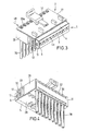
- the inner housing 1 has the front plug-in face end wall 3 with plug-in openings 4 a arranged in a row in the longitudinal direction of the housing for gripping through, for example, mating plug contact pins (not shown).
- the inner housing 1 is also formed by the broad side walls 4, 5, the narrow side end walls 6, 7 and the rear open 8.
- contact chambers 9, which extend from the open rear 8 to the plug face end wall 3 and are arranged next to one another in the longitudinal direction of the housing , in each of which there is an insulation displacement contact element 10 formed from a stamped sheet metal part.
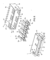
- the insulation displacement contact elements 10 inserted in the chambers 9 have in their longitudinal center a U-shaped spring arm base 14 with a spring arm base web 15 and two spring arm leg webs 16, 17.
- Contact spring arms 18 extend from the spring arm leg webs 16, 17 to the plug face end wall 3 as far as the mouth of the plug openings 4a.
- an insulation displacement arm base web 19 which is also U-shaped, is connected to the spring arm base web 15 and is wider than the spring arm base web 15 and from which the insulation displacement arm webs 21, 22 are angled in the same direction as the spring arm leg webs 16, 17 from Spring arm base web 15.
- the cutting clamps 23 extend from the insulation displacement leg webs 21, 22 opposite to the spring arms 18, each with the two cutting edges 24 running parallel to one another and the insulation displacement slot 25 therebetween.
- Short plug-in holes 34 are formed in the broad side wall 27 and short-hole holes 35 are formed in the broad side wall 28, just above the bottom wall 31, each of which is arranged in a row at a distance from one another, the holes 34, 35 being of equal size and in each case in alignment with one another.
- the holes 35 have an insertion funnel 36 on the outer wall side and the holes 34 are connected on the outer wall side to a respective blind groove 37 extending from the bottom wall 31.
- slots 38 are made in the bottom wall 31, so that each hole 34, 35 is assigned a slot 38 into which the free end areas of the cutting edges 24 can engage.
- the connector is assembled by inserting the insulation displacement contact elements 10 into the chambers 9 and then pushing the filled inner housing 1 with the blades protruding from the housing into the outer housing 2 until the locking webs 12 snap into the associated locking slots 32, from which one The locking position of the housings 1 and 2 results (Fig. 3,4).
- the cutting edges 24 are then still above the holes 34, 35.
- An electrical line 39 is then inserted through each hole 35 until its end region engages in the associated hole 34, penetrates the groove 37 and aligns its end 39a with the surface of the broad side wall 27.
- the inner housing is then pressed deeper into the surrounding housing 2 until each latching web 11 engages in the associated latching slot 32 and each latching web 12 in the associated latching slot 33.
- FIGS. 5 to 8 The further embodiment of a plug according to the invention shown in FIGS. 5 to 8 is for contacting a thin, e.g. 1.3 to 1.8 mm thick printed circuit board.
- the plug openings 4a are missing; instead, the inner housing 1 has a slot 4b which extends from the narrow side end wall 6 to the narrow side end wall 7 and passes through the housing body and opens towards the mating face end wall 3, which is only interrupted by coding or positioning webs 42 which extend transversely to the mating slot and which are broken into corresponding ones slot-shaped coding or positioning recesses 43 of the circuit board 41 grip.
- slot-shaped recesses 44 are made in the narrow side walls 29, 30 of the surrounding housing 2, into which the circuit board 41 also engages and the bottom edge 45 of which can form a stop or a plug-in limitation for the circuit board 41.
- the housing detents 11, 12 and 32, 33 are on the wide side walls 4, 5 and 27, respectively , 28, whereby a plurality of locking webs 11 and 12 and, accordingly, a plurality of locking slots 32 and 33 are expediently provided next to one another.
- the insulation displacement contact elements 10a which are shown in FIGS. 5 and 6, are particularly suitable for contacting the printed circuit board 41 and are similar to the insulation displacement contact elements 10 in the insulation displacement area.
- the plug-in contact area with the spring arm base 14a has two U-shaped spring arm connections 15a arranged at a lateral distance from one another, whose U-leg webs 16a, 17a with the insulation displacement arm leg webs 21, 22 and whose base webs 15b with the insulation displacement arm base web 19 are aligned, U-leg webs 15c extending parallel to the U-leg webs 16a, 17a are angled at right angles from the respective base web 15b and the contact spring arms 18 are connected to the U-leg webs 15c.
- the plug contact area is expediently equipped with an essentially U-shaped outer spring 46, the spring arms 48 of which rest in the area of the spring arm base 47 in the space between the U-leg webs 16a, 17a and 15c and press from the outside onto the contact spring arms 18, their spring arm base 47 on the rear edges of the spring arm connections 15a. It is expedient to secure the spring arms 48 with a tab 49 bent from the U-leg webs 16a, 17a.
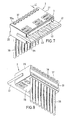
- the insulation displacement contact element 61 has a spring arm base 62 with a U-shaped cross section with a spring arm base web 63 and two spring arm leg webs 64, 65.
- a contact spring arm 66 extends forwards from the spring arm leg webs 64, 65, so that the two contact spring arms 66 lie opposite one another in the form of a flat fork spring.
- the spring arm leg webs 64, 65 are connected to the longitudinal edges of the spring arm base web 63 and angled opposite one another at right angles upwards, so that they stand upright with respect to the spring arm base web 63.
- the contact spring arms 66 are arranged and shaped symmetrically to a longitudinal center plane 67 extending between them and perpendicular to the spring arm base web 63.
- an insulation displacement arm base web 71 of an insulation displacement base base 73 Aligned to the rear on the spring arm base web 63, an insulation displacement arm base web 71 of an insulation displacement base base 73, which is also U-shaped in cross section, which is wider than the spring arm base web 63 is connected 71 angled upwards at a right angle, like the spring arm leg webs 64, 65 from the spring arm base web 63.
- an insulation displacement clamp 76 With the two extending in the longitudinal direction of the insulation displacement contact element 61 extends opposite to the contact spring arms 66, that is to the rear Cut 77 and the insulation displacement slot 78 between them.
- the Insulation clamps 76 protrude beyond the rear end or the rear transverse edge of insulation displacement arm base web 71.
- a form-fitting holder 88 is provided, which is formed by latching cams 89 on the spring arm leg webs 84, 85 and fixing cams 91 on the spring arm leg webs 64, 65, which in the attached position of the outer spring 81 belong to the locking cutouts 92 in of the contact spring arm base 62 or fixing cutouts 93 in the spring arm base 82.
- the elements of the form-fitting holder 88 are provided in a transverse plane with respect to the longitudinal direction of the insulation displacement contact element in the central region of the contact spring arm base 62 and spring arm base 82.
- the fixing cams 91 protrude from the free longitudinal edges of the spring arm webs 64, 65 and are each bent at about 30 ° towards each other.
- the latching cams 89 are also arranged and bent toward one another in the region of the free longitudinal edges of the spring spring webs 84, 85, the latching cams 89 also being able to be bent in at a right angle.
- the latching cutouts 92 are arranged, into which the latching cams 89 snap due to the elasticity of the spring arm base 82.
- the fixing recesses 93 for the fixing cams 91 are punched opposite them in the spring arm base web 83.
- the spring arm leg webs 84, 85 are elastically bent out when the latching cams 89 strike the ramps formed by the roof-shaped oblique fixing cams 91, so that the outer spring 81 can be pushed on further until the locking cams 89 snap into the locking cutouts 92.
- the latching cams 89 preferably do not protrude from the free longitudinal edges of the spring arm leg webs 84, 85, but are formed by transverse incisions 95.
- the outer spring 81 is positively held against shifting on the contact spring arm base 62 in that the width of the locking cams 89 and / or fixing cams 91 is adapted to the corresponding dimension of the associated locking or fixing cutout 92, 93.
- FIGS. 6 to 9 differs essentially only by a different embodiment of the contact spring arm base and the form-fitting holder 88.
- two contact spring arm connections are provided, two contact spring arm base webs 96 , 97 are arranged which are spaced apart from one another and extend from the insulation displacement arm base web 71 extend forward in its plane.
- the spring arm leg webs 64, 65 are connected here to the longitudinal inner edges of the contact spring arm base webs 96, 97 and are also angled upwards at right angles.
- the width measured via the contact spring arm base webs 96, 97 corresponds to the width of the insulation displacement arm base web 71, the insulation displacement arm leg webs 74, 75 extending to the front ends of the contact spring arm base webs 96, 97. This stabilizes the latter. It is also possible to view the insulation displacement arm base web 71 and the contact spring arm base webs 96, 97 as a common base plate. In this case, the distance between the contact spring arm base webs 96, 97 is formed by a recess 98 in the common base web, which results after the spring arm leg webs 64, 65 have been bent up. The spring arm leg webs 64, 65 are cut out or free from the material area located between them and then bent up.
- the outer spring 81 is basically of the same design apart from the form-fitting holder 88, the spring arm webs 84, 85 overlapping the spring arm webs 64, 65, the spring arm base 82 extending from the front ends of the contact spring arm webs 96, 97 to extends to the trailing edge of the IDC base web 71.
- the free longitudinal edges of the spring arm leg webs 84, 85 rest on the insulation displacement arm base web 71 and the contact spring arm base webs 96, 97.
- the spring arm base web 83 lies on the free longitudinal edges of the contact spring arm webs 64, 65.
- the form-fitting holder 88 is formed by two bending tabs 101, which originally protrude upward from the free longitudinal edges of the insulation displacement arm webs 74, 75 and are bent or angled into suitably arranged fixing cutouts 102 on the spring arm base 82.
- the fixing cutouts 102 are located in the corner region of the spring arm base 82, so that the bending tabs 101 on contact edges formed by the fixing cutouts 102 103 of the spring arm leg webs 84, 85 rest and are countersunk in the fixing cutouts 102.
- the fixing cutouts 102 are adapted along the insulation displacement contact element 61 to the width of the bending tabs 102 with little movement play.
- the outer spring 81 is thus held in a positive manner on the contact spring arm base 82 in all directions.
- the insulation displacement arm webs 74, 75 are dimensioned somewhat higher than the contact arm arm webs 64, 65, so that the latter - as seen in the side view - are arranged centrally to the insulation displacement arm webs 74, 75.
- the outer spring 81 in particular in the embodiment according to FIGS. 1 to 5, is made of steel, as a result of which a satisfactory elasticity and strength is achieved.
- the material thickness of the outer spring 81 can be made thinner than the thickness of the blank forming the insulation displacement contact element 61.
- the insulation displacement contact element 61 and the outer spring 81 are integral sheet metal stampings.
Landscapes
- Connector Housings Or Holding Contact Members (AREA)
Applications Claiming Priority (4)
| Application Number | Priority Date | Filing Date | Title |
|---|---|---|---|
| DE9000483U | 1990-01-17 | ||
| DE9000483U DE9000483U1 (de) | 1990-01-17 | 1990-01-17 | Elektrischer Stecker |
| DE9001065U DE9001065U1 (de) | 1990-01-31 | 1990-01-31 | Elektrisches Schneidklemmkontaktelement |
| DE9001065U | 1990-01-31 |
Publications (2)
| Publication Number | Publication Date |
|---|---|
| EP0437782A2 true EP0437782A2 (fr) | 1991-07-24 |
| EP0437782A3 EP0437782A3 (en) | 1993-01-13 |
Family
ID=25956092
Family Applications (1)
| Application Number | Title | Priority Date | Filing Date |
|---|---|---|---|
| EP19900124797 Withdrawn EP0437782A3 (en) | 1990-01-17 | 1990-12-19 | Electric plug connector |
Country Status (1)
| Country | Link |
|---|---|
| EP (1) | EP0437782A3 (fr) |
Cited By (10)
| Publication number | Priority date | Publication date | Assignee | Title |
|---|---|---|---|---|
| US5364288A (en) * | 1992-07-24 | 1994-11-15 | North American Philips Corporation | Electrical connecting device |
| FR2709606A1 (fr) * | 1993-09-03 | 1995-03-10 | Grote & Hartmann | Elément de contact électrique. |
| DE19945412B4 (de) * | 1998-09-24 | 2008-01-10 | The Whitaker Corp., Wilmington | Elektrischer Kontakt und elektrischer Steckverbinder mit einem solchen Kontakt |
| DE102008051286A1 (de) * | 2008-10-10 | 2010-04-15 | Valeo Schalter Und Sensoren Gmbh | Kontaktiereinrichtung für Leiterplatten |
| EP2600470A1 (fr) * | 2011-11-29 | 2013-06-05 | ABB Schweiz AG | Dispositif de raccordement pour un câble plat et appareil électrique doté d'un câble plat raccordé |
| WO2013091009A1 (fr) | 2011-12-23 | 2013-06-27 | Tyco Electronics Services Gmbh | Système de câblage de télécommunications, et module de connexion électrique et interface de blindage associée |
| DE102012006500A1 (de) * | 2012-03-29 | 2013-10-02 | Abb Ag | Polklemme für einen Steckdoseneinsatz |
| DE102012103601A1 (de) * | 2012-04-24 | 2013-10-24 | Wago Verwaltungsgesellschaft Mbh | Gabelkontaktelement |
| IT201800005498A1 (it) * | 2018-05-18 | 2019-11-18 | Contatto da taglioe connettore elettrico per contattare un cavo isolato attraverso l'isolamento | |
| EP4026203B1 (fr) * | 2019-09-05 | 2024-10-09 | Harting Electronics GmbH | Connecteur encartable |
Citations (6)
| Publication number | Priority date | Publication date | Assignee | Title |
|---|---|---|---|---|
| DE2537421A1 (de) * | 1974-08-23 | 1976-07-08 | Thomas & Betts Corp | Verbinder |
| US4066316A (en) * | 1976-11-11 | 1978-01-03 | Bell Telephone Laboratories, Incorporated | Electrical connector construction |
| FR2463523A2 (fr) * | 1979-08-10 | 1981-02-20 | Bunker Ramo | Organe de raccordement, element de contact et connecteur electrique pour le raccordement sans denudage de fils electriques |
| EP0220884A2 (fr) * | 1985-10-18 | 1987-05-06 | Reliance Electric Company | Bloc à bornes avec des connecteurs à déplacement d'isolant |
| US4682839A (en) * | 1986-01-30 | 1987-07-28 | Crane Electronics, Inc. | Multi-row modular electrical connector |
| DE8806979U1 (de) * | 1988-05-27 | 1988-09-08 | Siemens AG, 1000 Berlin und 8000 München | Elektrischer Steckverbinder |
-
1990
- 1990-12-19 EP EP19900124797 patent/EP0437782A3/de not_active Withdrawn
Patent Citations (6)
| Publication number | Priority date | Publication date | Assignee | Title |
|---|---|---|---|---|
| DE2537421A1 (de) * | 1974-08-23 | 1976-07-08 | Thomas & Betts Corp | Verbinder |
| US4066316A (en) * | 1976-11-11 | 1978-01-03 | Bell Telephone Laboratories, Incorporated | Electrical connector construction |
| FR2463523A2 (fr) * | 1979-08-10 | 1981-02-20 | Bunker Ramo | Organe de raccordement, element de contact et connecteur electrique pour le raccordement sans denudage de fils electriques |
| EP0220884A2 (fr) * | 1985-10-18 | 1987-05-06 | Reliance Electric Company | Bloc à bornes avec des connecteurs à déplacement d'isolant |
| US4682839A (en) * | 1986-01-30 | 1987-07-28 | Crane Electronics, Inc. | Multi-row modular electrical connector |
| DE8806979U1 (de) * | 1988-05-27 | 1988-09-08 | Siemens AG, 1000 Berlin und 8000 München | Elektrischer Steckverbinder |
Cited By (20)
| Publication number | Priority date | Publication date | Assignee | Title |
|---|---|---|---|---|
| US5433626A (en) * | 1992-07-24 | 1995-07-18 | North American Philips Corporation | Electrical connecting device |
| US5492485A (en) * | 1992-07-24 | 1996-02-20 | North American Philips Corporation | Electrical connecting device |
| US5498173A (en) * | 1992-07-24 | 1996-03-12 | North American Philips Corporation | Electrical connecting device |
| US5562480A (en) * | 1992-07-24 | 1996-10-08 | North American Philips Corporation | Electrical connecting device |
| US5364288A (en) * | 1992-07-24 | 1994-11-15 | North American Philips Corporation | Electrical connecting device |
| FR2709606A1 (fr) * | 1993-09-03 | 1995-03-10 | Grote & Hartmann | Elément de contact électrique. |
| DE19945412B4 (de) * | 1998-09-24 | 2008-01-10 | The Whitaker Corp., Wilmington | Elektrischer Kontakt und elektrischer Steckverbinder mit einem solchen Kontakt |
| DE102008051286B4 (de) | 2008-10-10 | 2020-01-09 | Valeo Schalter Und Sensoren Gmbh | Kontaktiereinrichtung für Leiterplatten |
| DE102008051286A1 (de) * | 2008-10-10 | 2010-04-15 | Valeo Schalter Und Sensoren Gmbh | Kontaktiereinrichtung für Leiterplatten |
| EP2600470A1 (fr) * | 2011-11-29 | 2013-06-05 | ABB Schweiz AG | Dispositif de raccordement pour un câble plat et appareil électrique doté d'un câble plat raccordé |
| CN103138064A (zh) * | 2011-11-29 | 2013-06-05 | Abb瑞士有限公司 | 用于平带式缆线的联接装置和带有平带式缆线的电气装置 |
| WO2013091009A1 (fr) | 2011-12-23 | 2013-06-27 | Tyco Electronics Services Gmbh | Système de câblage de télécommunications, et module de connexion électrique et interface de blindage associée |
| EP2795742A4 (fr) * | 2011-12-23 | 2015-08-12 | Tyco Electronics Services Gmbh | Système de câblage de télécommunications, et module de connexion électrique et interface de blindage associée |
| DE102012006500A1 (de) * | 2012-03-29 | 2013-10-02 | Abb Ag | Polklemme für einen Steckdoseneinsatz |
| DE102012103601A1 (de) * | 2012-04-24 | 2013-10-24 | Wago Verwaltungsgesellschaft Mbh | Gabelkontaktelement |
| DE102012103601B4 (de) * | 2012-04-24 | 2014-07-31 | Wago Verwaltungsgesellschaft Mbh | Gabelkontaktelement |
| IT201800005498A1 (it) * | 2018-05-18 | 2019-11-18 | Contatto da taglioe connettore elettrico per contattare un cavo isolato attraverso l'isolamento | |
| EP3570378A1 (fr) * | 2018-05-18 | 2019-11-20 | TE Connectivity Italia S.r.l. | Contact tranchant et connecteur électrique pour contacter un fil isolé par isolation |
| CN110504575A (zh) * | 2018-05-18 | 2019-11-26 | 泰连意大利公司 | 用于穿过绝缘体接触绝缘导线的切割触头和电连接器 |
| EP4026203B1 (fr) * | 2019-09-05 | 2024-10-09 | Harting Electronics GmbH | Connecteur encartable |
Also Published As
| Publication number | Publication date |
|---|---|
| EP0437782A3 (en) | 1993-01-13 |
Similar Documents
| Publication | Publication Date | Title |
|---|---|---|
| DE69315966T2 (de) | Elektrischer Verbinder für einen Kartenleser | |
| DE2426373A1 (de) | Elektrischer verbinder | |
| DE9115318U1 (de) | Elektrischer Verbinder mit reduzierter Einführkraft | |
| DE1016344B (de) | Elektrisches Anschlussbrett | |
| EP0621661A2 (fr) | Socle pour appareillage électrique | |
| EP3490075A1 (fr) | Ensemble composé de connecteur enfichable et d'élément de retenue ainsi que connecteur enfichable et élément de retenue correspondant | |
| DE4305194A1 (fr) | ||
| EP0437782A2 (fr) | Fiche électrique | |
| DE3441416C2 (de) | Elektrische Steckverbindung | |
| DE19949387A1 (de) | Kontaktteil für Anschlussklemme | |
| DE2013883C3 (de) | Aus elastischem Kunststoffmaterial geformtes Isoliergehäuse | |
| EP0189730A1 (fr) | Fiche pour haute fréquence de commutation | |
| WO2000055943A1 (fr) | Connecteur electrique enfichable comprenant au moins un element de contact a guillotine constitue par une partie estampee en tole, et contre-connecteur correspondant | |
| DE4034094C2 (de) | Elektrisches Kontaktelement mit Kontaktfederarmen | |
| DE19945412B4 (de) | Elektrischer Kontakt und elektrischer Steckverbinder mit einem solchen Kontakt | |
| DE29613694U1 (de) | Steckverbinder | |
| EP0693801A1 (fr) | Connecteur électrique | |
| DE4205974C1 (en) | Electrical plug connector with built-in latching for pins - provides section formed on housing that locates against pin flange and is held by latch stage | |
| DE4433617C2 (de) | Elektrisches Steckverbindungsteil | |
| DE102014114352B3 (de) | Stiftleiste | |
| DE9000483U1 (de) | Elektrischer Stecker | |
| EP0742607A2 (fr) | Ressort de contact | |
| EP1286420B1 (fr) | Barette de connection pour télécommunication | |
| EP0892997A1 (fr) | Connecteur a fiches pour cables | |
| DE19519771C2 (de) | Führungsplatte für die Anschlußbeine eines Winkelsteckverbinders |
Legal Events
| Date | Code | Title | Description |
|---|---|---|---|
| PUAI | Public reference made under article 153(3) epc to a published international application that has entered the european phase |
Free format text: ORIGINAL CODE: 0009012 |
|
| AK | Designated contracting states |
Kind code of ref document: A2 Designated state(s): DE FR GB IT SE |
|
| PUAL | Search report despatched |
Free format text: ORIGINAL CODE: 0009013 |
|
| AK | Designated contracting states |
Kind code of ref document: A3 Designated state(s): DE FR GB IT SE |
|
| 17P | Request for examination filed |
Effective date: 19930113 |
|
| 17Q | First examination report despatched |
Effective date: 19940209 |
|
| STAA | Information on the status of an ep patent application or granted ep patent |
Free format text: STATUS: THE APPLICATION HAS BEEN WITHDRAWN |
|
| 18W | Application withdrawn |
Withdrawal date: 19950112 |