EP0437272A1 - Séchoir vertical - Google Patents
Séchoir vertical Download PDFInfo
- Publication number
- EP0437272A1 EP0437272A1 EP91100305A EP91100305A EP0437272A1 EP 0437272 A1 EP0437272 A1 EP 0437272A1 EP 91100305 A EP91100305 A EP 91100305A EP 91100305 A EP91100305 A EP 91100305A EP 0437272 A1 EP0437272 A1 EP 0437272A1
- Authority
- EP
- European Patent Office
- Prior art keywords
- air
- web
- shaft
- drying
- air flow
- Prior art date
- Legal status (The legal status is an assumption and is not a legal conclusion. Google has not performed a legal analysis and makes no representation as to the accuracy of the status listed.)
- Withdrawn
Links
Images
Classifications
-
- F—MECHANICAL ENGINEERING; LIGHTING; HEATING; WEAPONS; BLASTING
- F26—DRYING
- F26B—DRYING SOLID MATERIALS OR OBJECTS BY REMOVING LIQUID THEREFROM
- F26B3/00—Drying solid materials or objects by processes involving the application of heat
- F26B3/28—Drying solid materials or objects by processes involving the application of heat by radiation, e.g. from the sun
- F26B3/283—Drying solid materials or objects by processes involving the application of heat by radiation, e.g. from the sun in combination with convection
-
- F—MECHANICAL ENGINEERING; LIGHTING; HEATING; WEAPONS; BLASTING
- F26—DRYING
- F26B—DRYING SOLID MATERIALS OR OBJECTS BY REMOVING LIQUID THEREFROM
- F26B13/00—Machines and apparatus for drying fabrics, fibres, yarns, or other materials in long lengths, with progressive movement
- F26B13/10—Arrangements for feeding, heating or supporting materials; Controlling movement, tension or position of materials
Definitions
- the invention relates to a drying chute, e.g. Predrying shaft, for the heat treatment of a vertically guided web of material having a certain width, with radiation heaters arranged on top of each other on both sides of the web at a distance and above the height of the drying shaft, on the back of which there is also an air flow duct to the width of the web Air flow guide directed upward downward, the outflow opening of which is arranged on the underside of the drying shaft and is directed against the associated web side.
- a drying chute e.g. Predrying shaft
- Predrying shaft for the heat treatment of a vertically guided web of material having a certain width
- radiation heaters arranged on top of each other on both sides of the web at a distance and above the height of the drying shaft, on the back of which there is also an air flow duct to the width of the web Air flow guide directed upward downward, the outflow opening of which is arranged on the underside of the drying shaft and is directed against the associated web side.
- a device of this type is known from DE-OS 14 60 660.
- the radiant heaters are arranged at a greater distance from one another and between the radiators nozzles through which the air circulated in the drying shaft is blown onto the web. It is important when drying by means of radiant heating elements that the liquid evaporated by the high radiation energy be removed as quickly as possible in order to bring the radiation energy to the remaining liquid and thus to be able to evaporate further liquid. It is therefore also known from the aforementioned publication to heat the transport air before contact with the goods by separate radiators and - as usual during drying - to repel the air saturated with liquid and to add fresh air accordingly.
- the invention has for its object to build a drying shaft that is simple in construction and thus inexpensive to manufacture, and additionally ensures effective evacuation of the vaporized liquid by skillful air conduction, possibly even without additional heat energy is required.
- the invention advantageously takes other paths.
- the required amount of air is not circulated in the system, but always only fresh air is led through the treatment channel parallel to the web.
- the air necessary to remove the resulting amount of steam is not blown onto the web between the individual radiant heaters, but is only guided from bottom to top along the web, at high speed. Since, of course, this air necessary for removal must not be cold, i.e.
- the ambient air at the top of the dryer is introduced into the air flow duct through an air slot and then guided from top to bottom along the back of the radiant heater, whereby on the one hand the flowing air forms an insulation to the outside atmosphere and on the other hand this air flowing there is sufficiently heated by the waste heat from the radiant heater. Due to these measures, an effective removal of the amounts of steam generated during drying of the web is guaranteed, simply because the fresh air now flowing parallel to the web is not yet filled with essential steam and, as a result, can absorb a lot of the steam generated by the radiation energy. Since no additional heating energy is required to heat this amount of air, it is also possible to remove all of the air flowing through the treatment duct from the system on the top of the drying shaft without additional heating energy loss and to lead to the exhaust duct.
- the material web is generally guided from top to bottom through the drying shafts, that is to say the treatment air is washed around it in countercurrent.
- This driving style has several advantages. On the one hand, the countercurrent system is always implemented, so that the material web that runs out at the lower exit of the drying shaft and therefore drier does not come into contact with moist, but with dry air. Furthermore, with this mode of operation there is no problem of condensate formation on the deflection rollers, especially above the drying shaft.
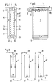
- the outer wall 1 of the drying shaft 2 is formed from a normal sheet metal wall, that is to say without or without substantial thermal insulation. However, it can be advantageous to design the inner sides 3 of the outer walls 1 to reflect heat rays. Immediately behind the outer wall 1 extends over the substantial height of the shaft 2, over the entire treatment width of the shaft, the air flow guide channel 4, the inner wall 1 'of which is also closed to the radiant heaters 5 adjacent on the inside, that is to say there are no openings for air nozzles to the radiators 5 are.
- an air inflow opening 6 over the entire treatment width which is simply open to the outside or, according to the other example 7, is provided with a supply duct 8 to which the fresh air is supplied with pressure by means of a driven fan 9.
- the sucked-in and dry fresh air is heated as it flows along the back of the radiant heater 5 and at the same time represents an insulation layer to the outside atmosphere.
- the air On the underside of the shafts 4, the air is deflected upwards and is via air slots 10, which also extend over the working width , blown against the web 11. According to the arrows 12, the web of material meets the air flow 13.
- the material web has passed through the radiant heating channel 14 in which it was heated on both sides with the radiant energy of the radiators 5.
Landscapes
- Engineering & Computer Science (AREA)
- Mechanical Engineering (AREA)
- General Engineering & Computer Science (AREA)
- Life Sciences & Earth Sciences (AREA)
- Microbiology (AREA)
- Textile Engineering (AREA)
- Drying Of Solid Materials (AREA)
Applications Claiming Priority (2)
| Application Number | Priority Date | Filing Date | Title |
|---|---|---|---|
| DE19904000622 DE4000622A1 (de) | 1990-01-11 | 1990-01-11 | Trockenschacht |
| DE4000622 | 1990-01-11 |
Publications (1)
| Publication Number | Publication Date |
|---|---|
| EP0437272A1 true EP0437272A1 (fr) | 1991-07-17 |
Family
ID=6397878
Family Applications (1)
| Application Number | Title | Priority Date | Filing Date |
|---|---|---|---|
| EP91100305A Withdrawn EP0437272A1 (fr) | 1990-01-11 | 1991-01-11 | Séchoir vertical |
Country Status (2)
| Country | Link |
|---|---|
| EP (1) | EP0437272A1 (fr) |
| DE (1) | DE4000622A1 (fr) |
Cited By (2)
| Publication number | Priority date | Publication date | Assignee | Title |
|---|---|---|---|---|
| EP0631098A1 (fr) * | 1993-06-22 | 1994-12-28 | Ciba-Geigy Ag | Sécheur en continu pour articles de forme plane, et installation de revêtement incorporant un tel sécheur |
| CN110631344A (zh) * | 2019-09-21 | 2019-12-31 | 阜阳恒泰纺织有限公司 | 一种纺织棉线用干燥装置 |
Families Citing this family (2)
| Publication number | Priority date | Publication date | Assignee | Title |
|---|---|---|---|---|
| CN116379735B (zh) * | 2023-03-23 | 2023-11-10 | 佛山市科蓝环保科技股份有限公司 | 布料预烘干装置及布料烘干系统 |
| CN116294507B (zh) * | 2023-03-23 | 2024-04-05 | 佛山市科蓝环保科技股份有限公司 | 一种布料烘干系统 |
Citations (9)
| Publication number | Priority date | Publication date | Assignee | Title |
|---|---|---|---|---|
| FR68000E (fr) * | 1955-07-28 | 1958-03-26 | Perfectionnements au séchage de tissus, papiers, cartons et autres matières en bandes | |
| DE1460660A1 (de) * | 1963-09-21 | 1969-08-28 | Friedr Haas Gmbh & Co Maschf | Vorrichtung zum Trocknen von Textilgewebebahnen |
| FR2399633A1 (fr) * | 1977-08-04 | 1979-03-02 | Brueckner Apparatebau Gmbh | Dispositif de sechage d'une bande de materiau en deplacement continu |
| US4379435A (en) * | 1981-10-19 | 1983-04-12 | Northern Telecom Limited | Drying oven for indefinite length material |
| EP0141227A2 (fr) * | 1983-09-23 | 1985-05-15 | FLEISSNER Maschinenfabrik AG | Séchoir vertical |
| EP0177774A2 (fr) * | 1984-09-10 | 1986-04-16 | Lohmann GmbH & Co. KG | Dispositif de séchage pour des matériaux en bande |
| GB2177187A (en) * | 1985-06-25 | 1987-01-14 | Monforts Gmbh & Co A | Infra-red web drier |
| FR2598495A1 (fr) * | 1986-05-09 | 1987-11-13 | Monforts Gmbh & Co A | Secheur a rayonnement infrarouge pouvant etre chauffe au gaz ou a l'electricite |
| DE3710787A1 (de) * | 1987-03-31 | 1988-10-13 | Babcock Textilmasch | Vorrichtung zur waermebehandlung von textilbahnen und dgl. |
-
1990
- 1990-01-11 DE DE19904000622 patent/DE4000622A1/de not_active Withdrawn
-
1991
- 1991-01-11 EP EP91100305A patent/EP0437272A1/fr not_active Withdrawn
Patent Citations (9)
| Publication number | Priority date | Publication date | Assignee | Title |
|---|---|---|---|---|
| FR68000E (fr) * | 1955-07-28 | 1958-03-26 | Perfectionnements au séchage de tissus, papiers, cartons et autres matières en bandes | |
| DE1460660A1 (de) * | 1963-09-21 | 1969-08-28 | Friedr Haas Gmbh & Co Maschf | Vorrichtung zum Trocknen von Textilgewebebahnen |
| FR2399633A1 (fr) * | 1977-08-04 | 1979-03-02 | Brueckner Apparatebau Gmbh | Dispositif de sechage d'une bande de materiau en deplacement continu |
| US4379435A (en) * | 1981-10-19 | 1983-04-12 | Northern Telecom Limited | Drying oven for indefinite length material |
| EP0141227A2 (fr) * | 1983-09-23 | 1985-05-15 | FLEISSNER Maschinenfabrik AG | Séchoir vertical |
| EP0177774A2 (fr) * | 1984-09-10 | 1986-04-16 | Lohmann GmbH & Co. KG | Dispositif de séchage pour des matériaux en bande |
| GB2177187A (en) * | 1985-06-25 | 1987-01-14 | Monforts Gmbh & Co A | Infra-red web drier |
| FR2598495A1 (fr) * | 1986-05-09 | 1987-11-13 | Monforts Gmbh & Co A | Secheur a rayonnement infrarouge pouvant etre chauffe au gaz ou a l'electricite |
| DE3710787A1 (de) * | 1987-03-31 | 1988-10-13 | Babcock Textilmasch | Vorrichtung zur waermebehandlung von textilbahnen und dgl. |
Cited By (3)
| Publication number | Priority date | Publication date | Assignee | Title |
|---|---|---|---|---|
| EP0631098A1 (fr) * | 1993-06-22 | 1994-12-28 | Ciba-Geigy Ag | Sécheur en continu pour articles de forme plane, et installation de revêtement incorporant un tel sécheur |
| US5567237A (en) * | 1993-06-22 | 1996-10-22 | Ciba-Geigy Corporation | Continuous drier for board-shaped piece material and coating installation comprising such a continuous drier |
| CN110631344A (zh) * | 2019-09-21 | 2019-12-31 | 阜阳恒泰纺织有限公司 | 一种纺织棉线用干燥装置 |
Also Published As
| Publication number | Publication date |
|---|---|
| DE4000622A1 (de) | 1991-07-18 |
Similar Documents
| Publication | Publication Date | Title |
|---|---|---|
| DE3637737C2 (fr) | ||
| EP0167899B1 (fr) | Dispositif de séchage, notamment pour le bois de charpente | |
| DE4228698C2 (de) | Vorrichtung und Verfahren zur Kondensationstrocknung | |
| DE1410814B1 (de) | Chemischreinigungsmaschine | |
| AT401429B (de) | Vorrichtung zum trocknen von holz | |
| DE3019922C2 (fr) | ||
| DE2613963C2 (de) | Textilwärmebehandlungsvorrichtung insbesondere Spannrahmen | |
| DE8017935U1 (de) | Luftgekühlter Kondensations-Wärmetrockner | |
| DE3423561A1 (de) | Vorrichtung zur lufttrocknung | |
| DE2351280B2 (de) | Prallstrahltrockner für bahnförmiges Gut | |
| EP0298299B1 (fr) | Dispositif pour guider des bandes sans contact direct | |
| EP3341518B1 (fr) | Appareil ménager comprenant un dispositif de nettoyage pour échangeur de chaleur | |
| EP0437272A1 (fr) | Séchoir vertical | |
| EP0141227B1 (fr) | Séchoir vertical | |
| WO2008128887A1 (fr) | Lave-linge automatique apte au séchage | |
| DE4026107A1 (de) | Konvektions-trocken und/oder -fixiermaschine | |
| DE2132265B2 (de) | Verdunstungskühler zum Kühlen von in einem Rohrsystem geförderten Dämpfen oder Flüssigkeiten | |
| EP0130579B1 (fr) | Dispositif pour le traitement en continu par la chaleur, par exemple le séchage, de matière textile en bande ou ruban | |
| EP0080573B1 (fr) | Machine à repasser à rouleaux, en particulier à plusieurs rouleaux | |
| DE641090C (de) | Verfahren und Vorrichtung zum Trocknen von Textilgut | |
| AT378469B (de) | Backofen | |
| DE2115640C3 (de) | Trocknungsanlage zum trocknen von einseitig offenen behaeltern, z.b. dosen | |
| DE3822624C2 (fr) | ||
| DE522029C (de) | Mehretagen-Spann- und -Trockenmaschine | |
| DE1927839A1 (de) | Trockenanlage fuer keramische,insbesondere grobkeramische Erzeugnisse |
Legal Events
| Date | Code | Title | Description |
|---|---|---|---|
| PUAI | Public reference made under article 153(3) epc to a published international application that has entered the european phase |
Free format text: ORIGINAL CODE: 0009012 |
|
| AK | Designated contracting states |
Kind code of ref document: A1 Designated state(s): CH DE FR GB IT LI |
|
| STAA | Information on the status of an ep patent application or granted ep patent |
Free format text: STATUS: THE APPLICATION IS DEEMED TO BE WITHDRAWN |
|
| 18D | Application deemed to be withdrawn |
Effective date: 19920118 |