EP0436859A2 - Shuttering for making prestressed concrete sleepers with immediate anchoring - Google Patents
Shuttering for making prestressed concrete sleepers with immediate anchoring Download PDFInfo
- Publication number
- EP0436859A2 EP0436859A2 EP90123890A EP90123890A EP0436859A2 EP 0436859 A2 EP0436859 A2 EP 0436859A2 EP 90123890 A EP90123890 A EP 90123890A EP 90123890 A EP90123890 A EP 90123890A EP 0436859 A2 EP0436859 A2 EP 0436859A2
- Authority
- EP
- European Patent Office
- Prior art keywords
- anchor plate
- wire
- formwork
- threshold
- tensioning
- Prior art date
- Legal status (The legal status is an assumption and is not a legal conclusion. Google has not performed a legal analysis and makes no representation as to the accuracy of the status listed.)
- Withdrawn
Links
Images


Classifications
-
- B—PERFORMING OPERATIONS; TRANSPORTING
- B28—WORKING CEMENT, CLAY, OR STONE
- B28B—SHAPING CLAY OR OTHER CERAMIC COMPOSITIONS; SHAPING SLAG; SHAPING MIXTURES CONTAINING CEMENTITIOUS MATERIAL, e.g. PLASTER
- B28B23/00—Arrangements specially adapted for the production of shaped articles with elements wholly or partly embedded in the moulding material; Production of reinforced objects
- B28B23/02—Arrangements specially adapted for the production of shaped articles with elements wholly or partly embedded in the moulding material; Production of reinforced objects wherein the elements are reinforcing members
- B28B23/04—Arrangements specially adapted for the production of shaped articles with elements wholly or partly embedded in the moulding material; Production of reinforced objects wherein the elements are reinforcing members the elements being stressed
- B28B23/06—Arrangements specially adapted for the production of shaped articles with elements wholly or partly embedded in the moulding material; Production of reinforced objects wherein the elements are reinforcing members the elements being stressed for the production of elongated articles
Definitions
- the invention relates to a formwork for producing prestressed concrete sleepers with an immediate bond, as described in the preamble of claim 1.
- the lost anchor plates each anchor, for example, two or four rods and have on their side facing away from the threshold means for connecting to tension rods, to which a clamping press can be attached.
- the smooth tension wires are cut to the desired length, passed through bores in the anchor plate with a slightly larger diameter than that of the rod cross-section, and then provided at their ends with swaged heads that anchor the tension wires in the anchor plate.
- the bundle of tensioning wires with anchor plates prepared in this way is installed in the sleeper formwork and prestressed against the end faces of the formwork. Then concrete is poured into the formwork and after it has hardened sufficiently, the anchors are loosened and the tension rods are unscrewed from the anchor plate and removed. This transfers the pre-tension from the tension wires to the concrete of the sleeper via the anchor plates.
- the threshold can be lifted out of the formwork.
- the anchor plates are lost.
- the former production method A it is only possible to pretension a limited number of tension wires.
- the points of attack for the drawing heads at the rod ends are relocated in front of the level of the formwork into the concrete of the sleeper, so that the sleeper is unimpeded after the concrete has hardened and the pulling heads removed from the threshold tension wire ends protruding into the formwork can be lifted out of the formwork.
- These sinking constructions do not allow the use of conventional bundle presses.
- the pulling head to be attached to each individual tension wire has a minimum size, which requires a corresponding minimum distance to the next pulling head. This minimum distance corresponds to a maximum number of tension wires assigned to the predetermined end face of the threshold, which can be arranged on this end face.
- Manufacturing method B uses smooth reinforcement bars and therefore cannot apply the prestressing forces to the threshold concrete via composite.
- the tension wire anchors become part of the threshold and are therefore lost.
- the loss of the anchor plates means that sleeper production becomes more expensive.
- the wire heads must also be pushed onto the bars mounted in the reinforcement cage for at least one anchoring side, which represents a considerable hindrance to this operation.
- the tension wires are temporarily anchored in an anchor plate, which - as is known from manufacturing process B - has means for fastening a tension rod to which the Clamping press can be used.
- the anchor plate enables the arrangement of practically any number of tensioning wires in the sleeper and their simultaneous prestressing with a press in one operation, without the need for a pulling head which requires space at each tensioning wire end.
- the anchor plate is recovered in order to economically exploit the property of the ribbed tensioning wire in introducing its tension into the threshold concrete via adhesive bond.
- the subclaims relate to configurations of the formwork by means of different designs of the anchor plate forming part of the end formwork, which allow the anchor plates to be recovered after the concrete of the threshold has sufficiently hardened and after the tension member for the tensioning press has been released from the anchor plate.
- the anchoring devices in the formwork according to claims 6 to 14 additionally solve the task of being able to emerge the wire heads on both tension wire ends independently of the anchoring in the anchor plate and of the assembly of the tensioning bundle. This significantly simplifies the upsetting process and the assembly of the tension bundle in the formwork.
- the tension wire anchors for the recovery of the anchor plates can be released non-destructively in these devices.
- the claims 15 to 20 specify expedient shapes of the anchor plate, which should facilitate the removal of the threshold and the recovery of the anchor plate.
- the anchoring device comprises the anchor plate 2 with bushings 3 for the tensioning wires 5.
- the tie rod 4 is detachably connected to the anchor plate 2. It can be connected to it via a bore 40 arranged in the center of gravity of the tensioning wires 5, for example by means of a threaded connection.
- the tensioning wires 5 are anchored on the side of the anchor plate 2 facing away from the threshold 7 by upset wire heads 6.
- An intermediate layer 9 with reduced strength or a flexible layer 10 can be arranged between the anchor plate 2 and the end face 8 of the threshold 7.
- the intermediate layer 9 is intended to reduce the cutting effort when severing the wire heads according to claim 4. Due to the flexibility of the layer 10, the anchor plate 2 can be pressed against the end face 8 of the threshold 7. The resulting gap 11 between the anchor plate 2 and the wire head makes a method according to claim 5 or a device according to claim 10 applicable.
- FIG. 5 shows a milling cutter with which the wire heads 6 are milled.
- tools 14 that are moved in slots 13 of an anchor plate 2.2 separate the wire heads 6.
- the wire heads 6 are blasted off by sudden heating with an arc 15.
- FIGS. 8 to 16 show examples of anchor plates in which the tension wire anchorings can be detached from the threshold without being destroyed.
- the anchor plate 2.3 according to FIG. 8 has keyhole-shaped feedthroughs 16, consisting of a bore 17 and a slot 18 that widens the bore 17 in one direction.
- the diameter of the bore 17 is slightly larger than the diameter of the wire head 6, the width of the slot 18 is slightly wider than the thickness of the tension wire 5.
- the centers of the bores 17 and the axes of the slots 18 have at least one circle 19 around as a common geometric location the common pivot point 20.
- the prestressing reinforcement is preassembled by inserting the wire heads 6 through the bores 17 and pushing the shafts of the tensioning wires 5 into the slots 18.
- the wire heads 6 When the tensioning wires 5 are tensioned after the tensioning reinforcement has been installed in the formwork, the wire heads 6 rest on the edges of the slots 18 and anchor the tension wires 5. After striking the concrete threshold, pressing the plate - for example if an elastic layer 10 is provided - loosens the contact pressure of the wire heads 6 in the slots 18, and the plate can be rotated and released in the direction of the arrow. Correspondingly, the wire heads 6 are anchored in the anchor plate 2.4 according to FIG. 9 and, after stripping the threshold, are loosened again by pushing the shafts of the tension wires 5 into the slots 18, 21 by pressing down the anchor plate 2.4 and moving them upward.
- FIGS. 10 and 11 instead of an anchor plate with keyhole-shaped bushings 16, according to FIGS. 10 and 11, anchor plates 2.5 with bores 22 which are round in cross section and have a diameter slightly larger than the diameter of the wire head 6, and fork-shaped disks 23 provided with a slot 24 for anchoring the tension wires 5 to be used.
- the slot 24 of the disk 23 encompasses the shaft of the tensioning wire 5 behind the wire head 6.
- FIG. 11 also shows the example of a bushing 3.4 with bushing 3.4 that widens conically on the threshold side to a larger part 27 of the plate thickness.
- the tension wires 5 are by conical anchoring parts 25, which are self-locking around their shaft. If the wire head 6 is relieved by pressing the anchor plate 2.6 against a resilient layer 10, springs 39 press the anchoring parts 25 apart and the anchor plate 2.6 can be pulled off over the wire heads.
- the tension wire 5 protrudes as little as possible from the end face 8 of the finished sleeper 7 after the anchor plate 2 has been released.
- This is achieved by countersinking the wire heads 6 on the side of the anchor plate facing away from the threshold 7. Sufficiently, this is done in the anchor plate 2.1, for example in FIGS. 5 and 7, where the wire heads 6 have to be removed to release the anchor plate.
- an even deeper depression of the wire head 6 is expedient in order to make the wire head 6 also disappear in the plane of the end face 8 of the threshold 7.
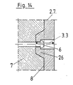
- anchor plates 2.7 according to FIG. 14 which have templates 26 on the bushings 3.3 on the side facing the concrete. By means of the template 26, the shoulder for the clamping head anchoring can be sunk in the implementation 3.3 beyond the thickness of the anchor plate 2.7.
- a bushing 28.1 or 28.2 is provided in the anchor plate 2.8 or 2.9 for each tensioning wire 5, the lower section 29.1 or 29.2 facing the threshold 7 has a clear diameter which is slightly larger than the outer diameter of the wire head 6, and whose outer section 30.1 or 30.2 facing away from the threshold 7 is considerably widened to accommodate multi-part wire head anchorings 31.1 or 31.2 and is provided with an internal thread 32.1 or 32.2.
- the wire head anchoring 31.1 or 31.2 comprises the chuck 36.1 or 36.2 consisting of several segments, which rests on the shoulder 33.1 or 33.2 formed by the cross-sectional jump of the bushing 28.1 or 28..2 and the packer 34.1 or 34.2.
- the packer 34.1 or 34.2 has an external diameter and an external thread which corresponds to the internal diameter and internal thread of the outer section 30.1 or 30.2 of the bushing 28.1 or 28.2. Its head 35.1 or 35.2 corresponds to the shape of the chuck 36.1 or 36.2.
- the chuck 36.1 or 36.2 is pressed firmly against the shaft of the tensioning wire 5 inserted through the lower section 29.1 or 29.2 of the leadthrough 28.1 or 28.2 immediately behind the wire head 6 by screwing in the packer 34.1 or 34.2.
- the tension wire anchoring and thus the anchor plate 2.8 or 2.9 can be released again.
- the anchor plate 2.10 shows a suitable trapezoidal shape in the view according to FIG. 17.
- the tapering of the anchor plate 2.11 in the cross section according to FIG. 18, which is proposed in cross section after the side 38 facing away from the end face 8 of the threshold 7, serves to compensate for a possibly obstructing inclined position of the anchor plate when Clamping process.
- An anchor plate 2.12 according to claim 13 with a conical template 26 is provided with holes 40 perpendicular to the tension wire axis.
- Tubes 41 are rotatably arranged in the bores 40, for example by means of a key which engages in an Allen key 44 at their upper end.
- Each tube 41 has an opening 42 at the level of the section with a tensioning wire axis, with an adjoining slot 43 extending perpendicular to the axis of rotation of the tube 41 on the tube jacket.
- the wire head 6 of the tension wire 5 is pushed into the interior of the tube 41 through a bore 39 arranged in the axis of the tension wire 5 and the approximately 42 opening lying behind it, and by rotating the tube so that the slot 43 is in front of the wire head 6 slides over the shaft of the tensioning wire, anchored in the anchor plate 2.12.
- the anchor plate 2.12 in FIG. 21 offers a further variant for anchoring.
- the tension wire 5.1 is provided with a threaded head 45 which anchors by means of a threaded spindle 46 which rests in a conical passage 3.2 corresponding to the shape of the spindle.
- the threaded spindle 46 has means 47, by means of which it can be screwed onto the threaded head 45.
Abstract
Description
Die Erfindung betrifft eine Schalung zur Herstellung von Spannbetonschwellen mit sofortigem Verbund, wie es im Oberbegriff des Anspruches 1 gattungsmäßig beschrieben ist.The invention relates to a formwork for producing prestressed concrete sleepers with an immediate bond, as described in the preamble of
Es gibt verschiedene Verfahren zur Herstellung von Spannbetonschwellen. Eine einfache Herstellungsweise ist die in langem Spannbett, wie sie z.B. für Weichenschwellen üblich ist. Von zahlreichen Bahnbetriebsunternehmen wird jedoch eine Schwelle mit dem Kräfteverlauf angepaßtem, über die Länge der Schwelle variablem Querschnitt verlangt. Eine derartige Schwelle ist - weil sie eine hohe Maßgenauigkeit erfordert - im langen Spannbett nur mit hohem Aufwand und für zahlreiche Schwellentypen nicht wirtschaftlich herstellbar. Schwellen mit einer komplizierten Formgebung werden daher in Einzelschalungen bzw. in Batterien von Einzelschalungen gefertigt. Bei der Schwellenfertigung in Einzelschalungen gibt es wiederum zwei grundsätzlich unterschiedliche Herstellungsverfahren:
- - mit nachträglichem Verbund in leichten billigen Schalungen; es wird nachträglich gegen den erhärteten Beton der entschalten Schwelle vorgespannt mit dem Nachteil des nachträglichen Einfädelns und nachträglichen Spannens und der Notwendigkeit des Verpressens,
- - mit sofortigem Verbund, wobei die Spanndrähte gegen die dafür wesentlich schwerer und aufwendiger ausgebildete Schalung vor dem Einbringen des Betons gespannt werden; die betonierte Schwelle muß in der teuren Schalung länger verweilen und erfordert hohe Investitionen in eine große Anzahl umlaufender Schalsätze.
- - with subsequent joining in light, inexpensive formwork; it is subsequently pre-stressed against the hardened concrete of the deactivated threshold with the disadvantage of subsequent threading and subsequent tensioning and the need for pressing,
- - With immediate bond, the tensioning wires being tensioned against the formwork, which is much heavier and more complex, before the concrete is placed; the concrete threshold must remain in the expensive formwork for longer and requires high investments in a large number of rotating formwork sets.
Nach dem eingeführten Herstellungsverfahren A der Anmelderin in DE-GM 18 33 644 ist bekannt, Spannbetonschwellen mit gerippten Spanndrähten und sofortigem Verbund vorzuspannen, indem gerippte Spanndrähte gegen die Stirnwände der Schalung mit Mehrfachpressen in einem Arbeitsgang gespannt und verankert werden. Die Vorspannkraft wird nach Erhärtung des Betons durch Lösen de Spanndrahtverankerung in den Stirnwänden der Schalung durch Haftverbund von den Spanndrähten in den Schwellenbeton eingeleitet.
Nach DE-GM 17 44 448 ist ein weiteres Herstellungsverfahren B für Spannbetonschwellen mit sofortigem Verbund bekannt, bei dem die Spannkräfte aus glatten Spanndrähten durch verlorene Ankerplatten an den Stirnseiten der Schwellen in den Schwellenbeton eingeleitet werden. Die verlorenen Ankerplatten verankern jeweils z.B. zwei oder vier Stäbe und weisen auf ihrer der Schwelle abgekehrten Seite Mittel zum Verbinden mit Zugstäben auf, an denen eine Spannpresse ansetzbar ist. Die glatten Spanndrähte werden auf Sollänge geschnitten, durch Bohrungen in der Ankerplatte mit geringfügig größerem Durchmesser als dem des Stabquerschnitts hindurchgeführt und anschließend an ihren Enden mit aufgestauchten Köpfen versehen, die die Spanndrähte in der Ankerplatte verankern. Das so vorbereitete Bündel von Spanndrähten mit Ankerplatten wird in die Schwellenschalung eingebaut und gegen die Stirnflächen der Schalung vorgespannt. Danach wird Beton in die Schalung eingefüllt und nach dessen ausreichender Erhärtung werden die Verankerungen gelöst und die Zugstäbe aus der Ankerplatte herausgeschraubt und entfernt. Damit überträgt sich die Vorspannung aus den Spanndrähten über die Ankerplatten auf den Beton der Schwelle. Die Schwelle kann aus der Schalung ausgehoben werden. Die Ankerplatten sind verloren.According to the introduced manufacturing method A of the applicant in DE-GM 18 33 644 it is known to prestress prestressed concrete sleepers with ribbed tension wires and immediate bond by tensioning and anchoring ribbed tension wires against the end walls of the formwork with multiple presses in one operation. The prestressing force is introduced after the concrete has hardened by loosening the prestressing wire anchor in the end walls of the formwork by means of an adhesive bond from the prestressing wires into the threshold concrete.
According to DE-GM 17 44 448, another manufacturing process B for prestressed concrete sleepers with an immediate bond is known, in which the prestressing forces are made of smooth tension wires are introduced into the threshold concrete by lost anchor plates on the end faces of the sleepers. The lost anchor plates each anchor, for example, two or four rods and have on their side facing away from the threshold means for connecting to tension rods, to which a clamping press can be attached. The smooth tension wires are cut to the desired length, passed through bores in the anchor plate with a slightly larger diameter than that of the rod cross-section, and then provided at their ends with swaged heads that anchor the tension wires in the anchor plate. The bundle of tensioning wires with anchor plates prepared in this way is installed in the sleeper formwork and prestressed against the end faces of the formwork. Then concrete is poured into the formwork and after it has hardened sufficiently, the anchors are loosened and the tension rods are unscrewed from the anchor plate and removed. This transfers the pre-tension from the tension wires to the concrete of the sleeper via the anchor plates. The threshold can be lifted out of the formwork. The anchor plates are lost.
Nach dem erstgenannten Herstellungsverfahren A ist es nur möglich, eine begrenzte Zahl von Spanndrähten vorzuspannen. Mit Hilfe von platzaufwendigen, tief in die Stirnwand der Schalung eingesenkten Konstruktionen werden die Angriffspunkte für die Ziehköpfe an den Stabenden innen vor die Ebene der Schalung in den Beton der Schwelle verlegt, so daß die Schwelle nach dem Erhärten des Betons und dem Entfernen der Ziehköpfe unbehindert von aus der Schwelle in die Schalung hineinstehenden Spanndrahtenden aus der Schalung nach oben ausgehoben werden kann. Diese Einsenkkonstruktionen lassen den Einsatz herkömmlicher Bündelpressen nicht zu. Der an jedem einzelnen Spanndraht anzusetzende Ziehkopf besitzt eine Mindestbaugröße, die einen entsprechenden Mindestabstand zum nächsten Ziehkopf erfordert. Diesem Mindestabstand entspricht eine der vorgegebenen Stirnfläche der Schwelle zugeordnete maximale Anzahl von Spanndrähten, die auf dieser Stirnfläche angeordnet werden können.According to the former production method A, it is only possible to pretension a limited number of tension wires. With the help of space-consuming constructions deeply recessed into the front wall of the formwork, the points of attack for the drawing heads at the rod ends are relocated in front of the level of the formwork into the concrete of the sleeper, so that the sleeper is unimpeded after the concrete has hardened and the pulling heads removed from the threshold tension wire ends protruding into the formwork can be lifted out of the formwork. These sinking constructions do not allow the use of conventional bundle presses. The pulling head to be attached to each individual tension wire has a minimum size, which requires a corresponding minimum distance to the next pulling head. This minimum distance corresponds to a maximum number of tension wires assigned to the predetermined end face of the threshold, which can be arranged on this end face.
Das Herstellverfahren B verwendet glatte Bewehrungsstäbe und kann daher die Spannkräfte nicht über Verbund in den Schwellenbeton einleiten. Die Spanndrahtverankerungen werden Teil der Schwelle und sind damit verloren. Da die Ankerplatten jedoch einen nicht unbeachtlichen Kostenfaktor darstellen, bedeutet der Verlust der Ankerplatten eine Verteuerung der Schwellenherstellung. Bei dem Herstellverfahren B müssen außerdem die Drahtköpfe mindestens für eine Verankerungsseite auf die im Bewehrungskorb montierten Stäbe aufgestaucht werden, was eine erhebliche Behinderung dieses Arbeitsganges darstellt.Manufacturing method B uses smooth reinforcement bars and therefore cannot apply the prestressing forces to the threshold concrete via composite. The tension wire anchors become part of the threshold and are therefore lost. However, since the anchor plates represent a not inconsiderable cost factor, the loss of the anchor plates means that sleeper production becomes more expensive. In manufacturing method B, the wire heads must also be pushed onto the bars mounted in the reinforcement cage for at least one anchoring side, which represents a considerable hindrance to this operation.
Wechselnde Anforderungen an die Schwellentypen stellten die Aufgabe, unter Nutzung des Standes der Technik, wie er sich aus dem Herstellverfahren B ergibt, das Herstellverfahren A so weiterzuentwickeln, daß auf der gleichbleibenden Stirnfläche einer nach dem Verfahren A hergestellten Schwelle eine größere Anzahl von Spanndrähten untergebracht und mit einem einfachen und wirtschaftlichen Spannverfahren vorgespannt werden kann.Changing demands on the types of sleepers set the task, using the state of the art, as it results from manufacturing process B, to further develop manufacturing process A in such a way that one manufactured according to process A on the constant end face Threshold accommodates a larger number of tension wires and can be pre-tensioned with a simple and economical tensioning method.
Die Aufgabe wird durch die im kennzeichnenden Teil des Anspruchs 1 beschriebene Schalung gelöst. Um jede statisch erforderliche Anzahl von Spanndrähten in die Schwelle einbauen zu können, werden die Spanndrähte temporär in einer Ankerplatte verankert, die auf der der Stirnseite der Schwelle abgekehrten Seite - wie aus dem Herstellverfahren B bekannt - Mittel aufweist zum Befestigen eines Spannstabes, an dem die Spannpresse ansetzbar ist. Die Ankerplatte ermöglicht die Anordnung einer praktisch beliebigen Anzahl von Spanndrähten in der Schwelle und deren gleichzeitige Vorspannung mit einer Presse in einem Arbeitsgang, ohne daß an jedem Spanndrahtende ein Platz beanspruchender Ziehkopf angesetzt werden muß. Um die Eigenschaft des gerippten Spanndrahtes, seine Spannkraft über Haftverbund in den Schwellenbeton einzuleiten, wirtschaftlich auszunutzen, wird die Ankerplatte wiedergewonnen.The object is achieved by the formwork described in the characterizing part of
Die Unteransprüche betreffen Ausgestaltungen der Schalung durch unterschiedliche Ausbildungsformen der einen Teil der Stirnschalung bildenden Ankerplatte, die die Wiedergewinnung der Ankerplatten nach ausreichender Erhärtung des Betons der Schwelle und nach dem Lösen des Zugglieds für die Spannpresse aus der Ankerplatte zulassen. Dabei lösen die Verankerungsvorrichtungen in den Schalungen nach den Ansprüchen 6 bis 14 zusätzlich die Aufgabe, die Drahtköpfe an beiden Spanndrahtenden unabhängig von der Verankerung in der Ankerplatte und von der Montage des Spannbündels aufstauchen zu können. Der Aufstauchvorgang und die Montage des Spannbündels in der Schalung werden dadurch wesentlich vereinfacht. Zugleich lassen sich bei diesen Vorrichtungen die Spanndrahtverankerungen zur Wiedergewinnung der Ankerplatten zerstörungsfrei lösen. In den Ansprüchen 2 bis 5 sind Ausbildungen der Ankerplatten angegeben, die ein bequemes Ansetzen bekannter Werkzeuge zum Abtrennen der Drahtköpfe der Verankerung zulassen, um so die Ankerplatte wiederzugewinnen. Die Ansprüche 2, 3 und 5 sehen Schneidwerkzeuge vor, die senkrecht zur Drahtachse den Spanndraht durchtrennen; nach Anspruch 4 wird der Drahtkopf durch in Drahtachse wirkende Werkzeuge zum spanabhebenden Abtragen - wie z.B. Bohr- oder Fräsmaschinen - aber auch Geräte zum Absprengen der Spannköpfe durch schlagartiges Aufheizen mit elektrischen Lichtbogen entfernt.The subclaims relate to configurations of the formwork by means of different designs of the anchor plate forming part of the end formwork, which allow the anchor plates to be recovered after the concrete of the threshold has sufficiently hardened and after the tension member for the tensioning press has been released from the anchor plate. Here the anchoring devices in the formwork according to
Die Ansprüche 15 bis 20 geben zweckmäßige Formgebungen der Ankerplatte an, die das Entschalen der Schwelle und die Wiedergewinnung der Ankerplatte erleichtern sollen.The
Die Erfindung wird durch Ausführungsbeispiele in den Fig. 1 bis 21 erläutert. Es zeigen:
- Fig. 1 bis 2
- eine Schalung mit erfindungsgemäßer Vorspanneinrichtung; Fig. 1 einen vertikal gelegten Längsschnitt, Fig. 2 einen Querschnitt,
- Fig. 3
- die Verankerung eines Spanndrahtes durch einen aufgestauchten Drahtkopf in der Ankerplatte,
- Fig. 4.1/2
- einen horizontal gelegten Längsschnitt durch eine ausgeschalte Schwelle mit erfindungsgemäßer Vorspanneinrichtung,
Fig. 4.1 mitZwischenlage 9 nachAnspruch 3,
Fig. 4.2 mitSchicht 10 nachAnspruch 5, - Fig. 5
- eine Verankerungsvorrichtung nach
Anspruch 4, an der Mittel zum spanabhebenden Abtragen der Drahtköpfe ansetzbar sind, - Fig. 6
- eine Verankerungsvorrichtung nach
Anspruch 2, - Fig. 7
- eine Verankerungsvorrichtung nach
Anspruch 4, an der Mittel zum Absprengen der Drahtköpfe ansetzbar sind, - Fig. 8
- die Sicht gegen eine Ankerplatte nach
Anspruch 6, - Fig. 9
- die Sicht gegen eine Ankerplatte nach
Anspruch 7, - Fig. 10 + 11
- Verankerungsvorrichtung nach den
Ansprüchen 8 und 17, Fig. 10 Ansicht, Fig. 11 Schnitt in Spanndrahtachse, - Fig. 12 + 13
- Verankerungsvorrichtung
nach den Ansprüchen 10und 12, Fig. 12 Schnitt in Spanndrahtachse, Fig. 13 Ansicht, mit Blickrichtung in Spanndrahtachse, - Fig. 14
- Schnitt durch eine Verankerungsvorrichtung nach Anspruch 16 in Spanndrahtachse,
- Fig. 15 + 16
- Zwei Beispiele einer Verankerungsvorrichtung nach Anspruch 11 . Schnitte in Spanndrahtachse.
- Fig. 17
- Ansicht einer
Ankerplatte nach Anspruch 18, - Fig. 18
- horizontaler Schnitt durch eine Ankerplatte nach Anspruch 19,
- Fig. 19 + 20
- Schnitte durch eine Ankerplatte nach Anspruch 13; Fig. 19 Horizontalschnitt, Fig. 20
Vertikalschnitt das Rohr 41 tangierend, - Fig. 21
- Schnitt durch eine Spanndrahtverankerung nach Anspruch 14.
- 1 to 2
- a formwork with a prestressing device according to the invention; 1 is a vertical longitudinal section, FIG. 2 is a cross section,
- Fig. 3
- the anchoring of a tension wire by an upset wire head in the anchor plate,
- Fig. 4.1 / 2
- a horizontally placed longitudinal section through a deactivated threshold with a pretensioning device according to the invention,
4.1 withintermediate layer 9 according toclaim 3,
4.2 withlayer 10 according toclaim 5, - Fig. 5
- An anchoring device according to
claim 4, on which means for machining the wire heads can be attached, - Fig. 6
- an anchoring device according to
claim 2, - Fig. 7
- an anchoring device according to
claim 4, to which means for detaching the wire heads can be attached, - Fig. 8
- the view against an anchor plate according to
claim 6, - Fig. 9
- the view against an anchor plate according to
claim 7, - Fig. 10 + 11
- Anchoring device according to
claims - Fig. 12 + 13
- Anchoring device according to
claims - Fig. 14
- Section through an anchoring device according to
claim 16 in the tension wire axis, - Figures 15 + 16
- Two examples of an anchoring device according to
claim 11. Cuts in the tension wire axis. - Fig. 17
- View of an anchor plate according to
claim 18, - Fig. 18
- horizontal section through an anchor plate according to
claim 19, - Fig. 19 + 20
- Sections through an anchor plate according to
claim 13; 19 horizontal section, FIG. 20 vertical section tangent to thepipe 41, - Fig. 21
- Section through a tension wire anchor according to
claim 14.
Fig. 1 zeigt eine Schalung 1 zur Herstellung von Spannbetonschwellen, in der Spanndrähte 5 mit einer erfindungsgemäßen Verankerungsvorrichtung vorspannfertig eingelegt sind. Die Verankerungsvorrichtung umfaßt die Ankerplatte 2 mit Durchführungen 3 für die Spanndrähte 5. Mit der Ankerplatte 2 ist der Zugstab 4 lösbar verbunden. Er ist an ihr über eine im Schwerpunkt der Spanndrähte 5 angeordnete Bohrung 40, beispielsweise durch eine Gewindeverbindung, anschließbar. Die Spanndrähte 5 sind auf der Schwelle 7 abgekehrten Seite der Ankerplatte 2 durch aufgestauchte Drahtköpfe 6 verankert. Zwischen der Ankerplatte 2 und der Stirnfläche 8 der Schwelle 7 können eine Zwischenlage 9 mit verminderter Festigkeit oder eine nachgiebige Schicht 10 angeordnet sein. Die Zwischenlage 9 soll den Schneidaufwand beim Abtrennen der Drahtköpfe nach Anspruch 4 vermindern. Durch die Nachgiebigkeit der Schicht 10 wird die Ankerplatte 2 gegen die Stirnfläche 8 der Schwelle 7 anpreßbar. Der dabei entstehende Zwischenraum 11 zwischen der Ankerplatte 2 und dem Drahtkopf macht ein Verfahren nach Anspruch 5 oder eine Vorrichtung nach Anspruch 10 anwendbar.1 shows a
Die Figuren 5 bis 7 zeigen Beispiele von Ankerplattenausbildungen, mit denen die Drahtköpfe 6 von den Spanndrähten 5 abgetrennt und die Ankerplatten 2 von der Schwelle 7 gelöst und wieder gewonnen werden können. Die dort verwendeten Ankerplatten 2.1, 2.2 sind zugleich Beispiele mit auf der der Schwelle 7 abgekehrten Seite 12 einer Ankerplatte 2 versenkt angeordneten Spannköpfen 6. Fig. 5 zeigt eine Bohrfräse, mit der die Drahtköpfe 6 abgefräst werden. Im Beispiel nach Fig. 6 trennen in Schlitzen 13 einer Ankerplatte 2.2 bewegte Werkzeuge 14 die Drahtköpfe 6 ab. Im Beispiel nach Fig. 7 werden die Drahtköpfe 6 durch schlagartige Erhitzung mit einem Lichtbogen 15 abgesprengt.Figures 5 to 7 show examples of anchor plate designs with which the wire heads 6 of the
Die Figuren 8 bis 16 zeigen Beispiele von Ankerplatten, bei denen die Spanndrahtverankerungen zerstörungsfrei von der Schwelle lösbar sind. Die Ankerplatte 2.3 nach Fig. 8 weist schlüssellochförmige Durchführungen 16, bestehend aus einer Bohrung 17 und einem die Bohrung 17 in einer Richtung erweiternden Schlitz 18 auf. Der Durchmesser der Bohrung 17 ist geringfügig größer als der Durchmesser des Drahtkopfes 6, die Breite des Schlitzes 18 geringfügig breiter als die Dicke des Spanndrahtes 5. Die Mittelpunkte der Bohrungen 17 und die Achsen der Schlitze 18 haben als gemeinsamen geometrischen Ort mindestens einen Kreis 19 um den gemeinsamen Drehpunkt 20. Die Spannbewehrung wird vormontiert, indem die Drahtköpfe 6 durch die Bohrungen 17 gesteckt und die Schäfte der Spanndrähte 5 in die Schlitze 18 geschoben werden. Beim Spannen der Spanndrähte 5 nach der Montage der Spannbewehrung in der Schalung legen sich die Drahtköpfe 6 an den Rändern der Schlitze 18 an und verankern die Spanndrähte 5. Nach dem Ausschalen der betonierten Schwelle wird durch Andrücken der Platte - beispielsweise wenn eine elastische Schicht 10 vorgesehen wird - der Anpreßdruck der Drahtköpfe 6 in den Schlitzen 18 gelockert, und die Platte kann in Pfeilrichtung gedreht und gelöst werden. In entsprechender Weise werden die Drahtköpfe 6 in der Ankerplatte 2.4 nach Fig. 9 verankert und nach dem Ausschalen der Schwelle durch Einschieben der Schäfte der Spanndrähte 5 in die Schlitze 18, 21 durch Niederdrücken der Ankerplatte 2.4 und Verschieben nach oben wieder gelöst.FIGS. 8 to 16 show examples of anchor plates in which the tension wire anchorings can be detached from the threshold without being destroyed. The anchor plate 2.3 according to FIG. 8 has keyhole-shaped
Anstelle einer Ankerplatte mit schlüssellochförmigen Durchführungen 16 können entsprechend Fig. 10 und 11 Ankerplatten 2.5 mit im Querschnitt runden Bohrungen 22 mit einem Durchmesser, der geringfügig größer als der Durchmesser des Drahtkopfes 6 ist, und gabelförmige mit Schlitz 24 versehene Scheiben 23 zur Verankerung der Spanndrähte 5 benutzt werden. Der Schlitz 24 der Scheibe 23 umfaßt dabei den Schaft des Spanndrahtes 5 hinter dem Drahtkopf 6. Zum Lösen der Ankerplatten 2.5 werden die Scheiben 23 von den Drahtschäften abgezogen. Fig. 11 zeigt außerdem das Beispiel einer Durchführung 3.4 mit schwellenseitig sich auf einen größeren Teil 27 der Plattendicke konisch erweiternder Durchführung 3.4 nach Anspruch 17.Instead of an anchor plate with keyhole-shaped
In der Ankerplatte 2.6 nach den Fig. 12 und 13 werden die Spanndrähte 5 durch konische Verankerungsteile 25, die sich selbstsperrend um deren Schaft legen, verankert. Wird der Drahtkopf 6 durch Andrücken der Ankerplatte 2.6 gegen eine nachgiebige Schicht 10 entlastet, drücken Federn 39 die Verankerungsteile 25 auseinander und die Ankerplatte 2.6 kann über die Drahtköpfe hinweg abgezogen werden.In the anchor plate 2.6 according to FIGS. 12 and 13, the
Es ist vorteilhaft, daß der Spanndraht 5 nach dem Lösen der Ankerplatte 2 möglichst wenig aus der Stirnfläche 8 der fertigen Schwelle 7 heraussteht. Dies wird durch Versenken der Drahtköpfe 6 auf der der Schwelle 7 abgekehrten Seite der Ankerplatte erreicht. In ausreichender Weise geschieht dies in der Ankerplatte 2.1 beispielsweise in Fig. 5 und 7, wo die Drahtköpfe 6 zum Lösen der Ankerplatte entfernt werden müssen. Bei zerstörungsfreiem Lösen der Ankerplatten ist ein noch tieferes Einsenken des Drahtkopfes 6 zweckmäßig, um auch den Drahtkopf 6 noch in der Ebene der Stirnfläche 8 der Schwelle 7 verschwinden zu lassen. Dies wird mit Ankerplatten 2.7 nach Fig. 14 erreicht, die an den Durchführungen 3.3 Vorlagen 26 auf der dem Beton zugekehrten Seite aufweisen. Durch die Vorlage 26 kann die Schulter für die Spannkopfverankerung in der Durchführung 3.3 über die Dicke der Ankerplatte 2.7 hinaus versenkt werden.It is advantageous that the
Bei den Beispielen von Verankerungsvorrichtungen nach Anspruch 11, die in den Figuren 15 und 16 dargestellt sind, ist in der Ankerplatte 2.8 bzw. 2.9 für jeden Spanndraht 5 eine Durchführung 28.1 bzw. 28.2 vorgesehen, deren unterer, der Schwelle 7 zugekehrter Abschnitt 29.1 bzw. 29.2 einen lichten Durchmesser aufweist, der geringfügig größer ist als der Außendurchmesser des Drahtkopfes 6, und deren der Schwelle 7 abgekehrter äußerer Abschnitt 30.1 bzw. 30.2 zur Aufnahme mehrteiliger Drahtkopfverankerungen 31.1 bzw. 31.2 erheblich aufgeweitet und mit Innengewinde 32.1 bzw. 32.2 versehen ist. Die Drahtkopfverankerung 31.1 bzw. 31.2 umfaßt das aus mehreren Segmenten bestehende Spannfutter 36.1 bzw. 36.2, das auf der durch den Querschnittssprung der Durchführung 28.1 bzw. 28..2 gebildeten Schulter 33.1 bzw. 33.2 ruht und den Packer 34.1 bzw. 34.2. Der Packer 34.1 bzw. 34.2 hat einen Außendurchmesser und ein Außengewinde, das dem Innendurchmesser und Innengewinde des äußeren Abschnitts 30.1 bzw. 30.2 der Durchführung 28.1 bzw. 28.2 entspricht. Sein Kopf 35.1 bzw. 35.2 entspricht der Form des Spannfutters 36.1 bzw. 36.2. Zur Verankerung des Spanndrahtes wird durch Eindrehen des Packers 34.1 bzw. 34.2 das Spannfutter 36.1 bzw. 36.2 fest an den Schaft des durch den unteren Abschnitt 29.1 bzw. 29.2 der Durchführung 28.1 bzw. 28.2 eingeführten Spanndrahtes 5 unmittelbar hinter dem Drahtkopf 6 angepreßt. Durch Herausdrehen des Packers 34.1 bzw. 34.2 ist die Spanndrahtverankerung und damit die Ankerplatte 2.8 bzw. 2.9 wieder lösbar.In the examples of anchoring devices according to
Eine für das Ausheben der Schwelle aus der Schalung zweckmäßige Trapezform zeigt die Ankerplatte 2.10 in der Ansicht nach Fig. 17. Die im Querschnitt nach der der Stirnfläche 8 der Schwelle 7 abgekehrten Seite 38 hin vorgeschlagene Verjüngung der Ankerplatte 2.11 im Querschnitt nach Fig. 18 dient dem Ausgleich einer möglicherweise hinderlichen Schrägstellung der Ankerplatte beim Spannvorgang.One for lifting the threshold out of the formwork The anchor plate 2.10 shows a suitable trapezoidal shape in the view according to FIG. 17. The tapering of the anchor plate 2.11 in the cross section according to FIG. 18, which is proposed in cross section after the
Eine Ankerplatte 2.12 nach Anspruch 13 mit einer konischen Vorlage 26 ist mit Bohrungen 40 senkrecht zur Spanndrahtachse versehen. In den Bohrungen 40 sind Rohre 41 - beispielsweise durch einen in einem Imbus 44 an ihrem oberen Ende angreifenden Schlüssel - drehbar angeordnet. Jedes Rohr 41 weist in Höhe des Schnitts mit einer Spanndrahtachse eine Öffnung 42 mit einem daran anschließenden senkrecht zur Drehachse des Rohres 41 sich auf dem Rohrmantel erstreckenden Schlitz 43 auf. Durch eine in der Achse des Spanndrahts 5 angeordnete Bohrung 39 und die dahinter liegende etwa gleiche große Öffnung 42 wird der Drahtkopf 6 des Spanndrahtes 5 in den Innenraum des Rohres 41 geschoben und durch Drehung des Rohres so, daß sich der Schlitz 43 vor dem Drahtkopf 6 über den Schaft des Spanndrahtes schiebt, in der Ankerplatte 2.12 verankert.An anchor plate 2.12 according to claim 13 with a
Eine weitere Variante für eine Verankerung bietet die Ankerplatte 2.12 in Fig. 21. Der Spanndraht 5.1 ist mit einem Gewindekopf 45 versehen, der mittels einer Gewindespindel 46, die in einer der Spindelform entsprechenden konischen Durchführung 3.2 ruht, verankert. Die Gewindespindel 46 weist Mittel 47 auf, mit deren Hilfe sie auf den Gewindekopf 45 aufdrehbar ist.The anchor plate 2.12 in FIG. 21 offers a further variant for anchoring. The tension wire 5.1 is provided with a threaded
Claims (19)
Applications Claiming Priority (2)
| Application Number | Priority Date | Filing Date | Title |
|---|---|---|---|
| DE4000729 | 1990-01-12 | ||
| DE4000729 | 1990-01-12 |
Publications (2)
| Publication Number | Publication Date |
|---|---|
| EP0436859A2 true EP0436859A2 (en) | 1991-07-17 |
| EP0436859A3 EP0436859A3 (en) | 1992-03-04 |
Family
ID=6397950
Family Applications (1)
| Application Number | Title | Priority Date | Filing Date |
|---|---|---|---|
| EP19900123890 Withdrawn EP0436859A3 (en) | 1990-01-12 | 1990-12-12 | Shuttering for making prestressed concrete sleepers with immediate anchoring |
Country Status (3)
| Country | Link |
|---|---|
| US (1) | US5196209A (en) |
| EP (1) | EP0436859A3 (en) |
| ES (1) | ES2023104A4 (en) |
Cited By (3)
| Publication number | Priority date | Publication date | Assignee | Title |
|---|---|---|---|---|
| DE4203223A1 (en) * | 1991-02-07 | 1992-08-13 | Wayss & Freytag Ag | Reinforcing rods for pre-stressed concrete sleepers - have oblique cross-pieces to receive tensioning nuts |
| EP1360397B2 (en) † | 2001-02-14 | 2009-11-11 | Max Bögl Bauunternehmung GmbH & Co. KG | Method and pallet for the production of a precise pre-cast concrete piece |
| CN111618976A (en) * | 2020-05-13 | 2020-09-04 | 中铁六局集团有限公司 | Construction method for prefabricated part fixed die table of fabricated building |
Families Citing this family (3)
| Publication number | Priority date | Publication date | Assignee | Title |
|---|---|---|---|---|
| US5366672A (en) * | 1993-03-18 | 1994-11-22 | Erico International Corporation | Method of forming concrete structures with a grout splice sleeve which has a threaded connection to a reinforcing bar |
| DE102012217823A1 (en) * | 2012-09-28 | 2014-04-03 | Harsco Infrastructure Services Gmbh | Wall formwork with sealing system |
| JP6384959B2 (en) * | 2015-03-11 | 2018-09-05 | 日本コンクリート工業株式会社 | Concrete product manufacturing apparatus and method for manufacturing concrete product |
Citations (9)
| Publication number | Priority date | Publication date | Assignee | Title |
|---|---|---|---|---|
| DE578768C (en) * | 1931-06-24 | 1933-06-16 | Otto Gloeser | Device for manufacturing reinforced concrete components |
| GB751631A (en) * | 1954-02-23 | 1956-07-04 | Concrete Patents Ltd | An improved method of tensioning and anchoring wires |
| FR1528919A (en) * | 1967-05-05 | 1968-06-14 | Anchoring device for steel wires with high elastic limit, usable in particular in the technique of prestressed concrete | |
| US3427772A (en) * | 1966-09-06 | 1969-02-18 | George W Williams | Apparatus for post-tensioning and interconnecting re-enforcing wires using key hole anchor plates in a concrete structure |
| AU473750B2 (en) * | 1973-04-09 | 1974-10-10 | Nippon Concrete Kogyo K.K. | Method of manufacturing prestressed concrete poles, piles andthe like |
| FR2230807A1 (en) * | 1973-05-21 | 1974-12-20 | Asserback Roy | |
| US3962786A (en) * | 1974-12-30 | 1976-06-15 | Nippon Concrete Industries Co. Ltd. | Apparatus for cutting rivets of tensioned reinforcement in the process of manufacturing concrete products |
| EP0057635A2 (en) * | 1981-02-04 | 1982-08-11 | BORCOMAN, Mircéa | Method, self supporting screens and installations for the improvement of the efficiency of the methods of making prestressed concrete products |
| DE3931201C1 (en) * | 1989-09-19 | 1990-11-22 | Wayss & Freytag Ag, 6000 Frankfurt, De | Concrete railway sleepers mfr. - uses moving frame mechanism which releases each sleeper immediately |
Family Cites Families (6)
| Publication number | Priority date | Publication date | Assignee | Title |
|---|---|---|---|---|
| US2655708A (en) * | 1952-09-23 | 1953-10-20 | Hector X Eschenbrenner | Method and apparatus for molding cementitious bodies |
| US2867884A (en) * | 1954-09-07 | 1959-01-13 | Prestressing Inc | Post-tensioned anchor device |
| US3236486A (en) * | 1958-02-17 | 1966-02-22 | Allen Form Corp | Waler brackets |
| US3462106A (en) * | 1967-10-11 | 1969-08-19 | Frank E Buyken | Waler bracket |
| US3583047A (en) * | 1969-08-20 | 1971-06-08 | Nippon Concrete Ind Co Ltd | Apparatus for manufacturing prestressed concrete poles,piles and the like |
| US3734453A (en) * | 1970-12-18 | 1973-05-22 | A Bailey | Tie rod assembly |
-
1990
- 1990-12-12 EP EP19900123890 patent/EP0436859A3/en not_active Withdrawn
- 1990-12-12 ES ES90123890T patent/ES2023104A4/en active Pending
-
1991
- 1991-01-14 US US07/641,157 patent/US5196209A/en not_active Expired - Lifetime
Patent Citations (9)
| Publication number | Priority date | Publication date | Assignee | Title |
|---|---|---|---|---|
| DE578768C (en) * | 1931-06-24 | 1933-06-16 | Otto Gloeser | Device for manufacturing reinforced concrete components |
| GB751631A (en) * | 1954-02-23 | 1956-07-04 | Concrete Patents Ltd | An improved method of tensioning and anchoring wires |
| US3427772A (en) * | 1966-09-06 | 1969-02-18 | George W Williams | Apparatus for post-tensioning and interconnecting re-enforcing wires using key hole anchor plates in a concrete structure |
| FR1528919A (en) * | 1967-05-05 | 1968-06-14 | Anchoring device for steel wires with high elastic limit, usable in particular in the technique of prestressed concrete | |
| AU473750B2 (en) * | 1973-04-09 | 1974-10-10 | Nippon Concrete Kogyo K.K. | Method of manufacturing prestressed concrete poles, piles andthe like |
| FR2230807A1 (en) * | 1973-05-21 | 1974-12-20 | Asserback Roy | |
| US3962786A (en) * | 1974-12-30 | 1976-06-15 | Nippon Concrete Industries Co. Ltd. | Apparatus for cutting rivets of tensioned reinforcement in the process of manufacturing concrete products |
| EP0057635A2 (en) * | 1981-02-04 | 1982-08-11 | BORCOMAN, Mircéa | Method, self supporting screens and installations for the improvement of the efficiency of the methods of making prestressed concrete products |
| DE3931201C1 (en) * | 1989-09-19 | 1990-11-22 | Wayss & Freytag Ag, 6000 Frankfurt, De | Concrete railway sleepers mfr. - uses moving frame mechanism which releases each sleeper immediately |
Cited By (3)
| Publication number | Priority date | Publication date | Assignee | Title |
|---|---|---|---|---|
| DE4203223A1 (en) * | 1991-02-07 | 1992-08-13 | Wayss & Freytag Ag | Reinforcing rods for pre-stressed concrete sleepers - have oblique cross-pieces to receive tensioning nuts |
| EP1360397B2 (en) † | 2001-02-14 | 2009-11-11 | Max Bögl Bauunternehmung GmbH & Co. KG | Method and pallet for the production of a precise pre-cast concrete piece |
| CN111618976A (en) * | 2020-05-13 | 2020-09-04 | 中铁六局集团有限公司 | Construction method for prefabricated part fixed die table of fabricated building |
Also Published As
| Publication number | Publication date |
|---|---|
| ES2023104A4 (en) | 1992-01-01 |
| EP0436859A3 (en) | 1992-03-04 |
| US5196209A (en) | 1993-03-23 |
Similar Documents
| Publication | Publication Date | Title |
|---|---|---|
| EP1105597B1 (en) | Device for fixing bars, posts, masts and such like in the ground and method for producing such a fixing device | |
| EP0211256A2 (en) | Anchor for embedding large loads in concrete | |
| EP0062155B1 (en) | Anchoring method for anchoring bolts or the like in concrete | |
| EP0317692A1 (en) | Tamping tool for a railway track tamping machine | |
| EP2216455B1 (en) | Connection element for wood compound, wood compound and method for production of same | |
| DE3004568A1 (en) | CUTTING TOOL WITH A REPLACEABLE CARBIDE CUTTING INSERT | |
| EP1722044A2 (en) | Shuttering tie as well as method for tying shuttering elements and method for removing a shuttering tie | |
| EP0436859A2 (en) | Shuttering for making prestressed concrete sleepers with immediate anchoring | |
| DE2925526A1 (en) | FASTENING ELEMENT AND RELATED TOOL | |
| EP2882557B1 (en) | Pre-stressing tendon separation device | |
| DE10114929C2 (en) | Spacers for non-load-bearing facing shells and methods of attachment | |
| DE3539612C1 (en) | Device for achieving a releasable interference fit between a component with a cylindrical bore and a component inserted into this bore | |
| EP1847666A1 (en) | Anchor device for tying of shuttering plates | |
| DE102018102678A1 (en) | Leveling aid, leveling device for plate-shaped floor or wall coverings and method for laying plate-shaped floor or wall coverings | |
| EP3330448A1 (en) | Device and method for connecting two components in a certain relative orientation and concrete structure created using the same | |
| EP1101883A1 (en) | Device for the execution of a reinforcement connection between a concrete construction element and a connected construction element | |
| EP3730263B1 (en) | Method for producing a plurality of cast elements made of prestressed concrete | |
| DE3941313A1 (en) | COMPOSITE STRUCTURE FOR A JOINT FOR SUPPORTING AN UPRISING WALL | |
| DE2424534C3 (en) | Fastening device for sleeper screws or the like | |
| DE10258435B4 (en) | anchoring element | |
| DE2322991A1 (en) | ANCHORING FOR ROPES OR THE SAME, IN PARTICULAR FOR THE TENSIONERS IN PREPARATORY CONCRETE CONSTRUCTION | |
| DE202023103836U1 (en) | Positioning device | |
| AT413581B (en) | METHOD FOR CONNECTING COMPONENTS | |
| DE19746111C2 (en) | Multi-part formwork body for producing undercut recesses, especially anchor holes, in concrete | |
| DE3338559A1 (en) | Method of fastening a coupling bolt in a stone and devices for carrying out this method |
Legal Events
| Date | Code | Title | Description |
|---|---|---|---|
| PUAI | Public reference made under article 153(3) epc to a published international application that has entered the european phase |
Free format text: ORIGINAL CODE: 0009012 |
|
| ITCL | It: translation for ep claims filed |
Representative=s name: LENZI & C. |
|
| AK | Designated contracting states |
Kind code of ref document: A2 Designated state(s): AT BE CH DE ES FR GB IT LI NL |
|
| GBC | Gb: translation of claims filed (gb section 78(7)/1977) | ||
| EL | Fr: translation of claims filed | ||
| TCNL | Nl: translation of patent claims filed | ||
| REG | Reference to a national code |
Ref country code: ES Ref legal event code: BA2A Ref document number: 2023104 Country of ref document: ES Kind code of ref document: A4 |
|
| PUAL | Search report despatched |
Free format text: ORIGINAL CODE: 0009013 |
|
| AK | Designated contracting states |
Kind code of ref document: A3 Designated state(s): AT BE CH DE ES FR GB IT LI NL |
|
| STAA | Information on the status of an ep patent application or granted ep patent |
Free format text: STATUS: THE APPLICATION HAS BEEN WITHDRAWN |
|
| 18W | Application withdrawn |
Withdrawal date: 19921009 |