EP0057635A2 - Method, self supporting screens and installations for the improvement of the efficiency of the methods of making prestressed concrete products - Google Patents
Method, self supporting screens and installations for the improvement of the efficiency of the methods of making prestressed concrete products Download PDFInfo
- Publication number
- EP0057635A2 EP0057635A2 EP82400136A EP82400136A EP0057635A2 EP 0057635 A2 EP0057635 A2 EP 0057635A2 EP 82400136 A EP82400136 A EP 82400136A EP 82400136 A EP82400136 A EP 82400136A EP 0057635 A2 EP0057635 A2 EP 0057635A2
- Authority
- EP
- European Patent Office
- Prior art keywords
- self
- supporting
- screens
- hand
- tensioning
- Prior art date
- Legal status (The legal status is an assumption and is not a legal conclusion. Google has not performed a legal analysis and makes no representation as to the accuracy of the status listed.)
- Granted
Links
- 238000000034 method Methods 0.000 title claims abstract description 68
- 238000009434 installation Methods 0.000 title claims description 101
- 239000011513 prestressed concrete Substances 0.000 title claims description 13
- 239000004567 concrete Substances 0.000 claims abstract description 26
- 238000004873 anchoring Methods 0.000 claims abstract description 16
- 230000002787 reinforcement Effects 0.000 claims description 53
- 238000004519 manufacturing process Methods 0.000 claims description 45
- 238000001816 cooling Methods 0.000 claims description 31
- 238000010438 heat treatment Methods 0.000 claims description 31
- 238000005096 rolling process Methods 0.000 claims description 20
- 239000002184 metal Substances 0.000 claims description 15
- 230000035939 shock Effects 0.000 claims description 10
- 238000005520 cutting process Methods 0.000 claims description 8
- 230000000903 blocking effect Effects 0.000 claims description 7
- 238000000926 separation method Methods 0.000 claims description 7
- 238000002635 electroconvulsive therapy Methods 0.000 claims description 5
- 238000007669 thermal treatment Methods 0.000 claims description 5
- 239000000872 buffer Substances 0.000 claims description 4
- 238000009826 distribution Methods 0.000 claims description 4
- 238000000605 extraction Methods 0.000 claims description 4
- 239000012528 membrane Substances 0.000 claims description 4
- 241000237536 Mytilus edulis Species 0.000 claims description 3
- 230000005484 gravity Effects 0.000 claims description 3
- 238000009413 insulation Methods 0.000 claims description 3
- 235000020638 mussel Nutrition 0.000 claims description 3
- 230000009286 beneficial effect Effects 0.000 claims description 2
- 238000001914 filtration Methods 0.000 claims description 2
- 238000012423 maintenance Methods 0.000 claims description 2
- 230000002093 peripheral effect Effects 0.000 claims description 2
- 230000000750 progressive effect Effects 0.000 claims description 2
- 239000002994 raw material Substances 0.000 claims description 2
- 239000011150 reinforced concrete Substances 0.000 claims description 2
- 238000003466 welding Methods 0.000 claims description 2
- 239000000853 adhesive Substances 0.000 claims 2
- 230000001070 adhesive effect Effects 0.000 claims 2
- 230000000295 complement effect Effects 0.000 claims 2
- 238000000465 moulding Methods 0.000 claims 1
- 210000003739 neck Anatomy 0.000 claims 1
- 238000010583 slow cooling Methods 0.000 claims 1
- 241001417494 Sciaenidae Species 0.000 description 3
- 230000001464 adherent effect Effects 0.000 description 2
- 238000004140 cleaning Methods 0.000 description 2
- 230000002040 relaxant effect Effects 0.000 description 2
- 241000288673 Chiroptera Species 0.000 description 1
- 238000007654 immersion Methods 0.000 description 1
- 239000004576 sand Substances 0.000 description 1
- 238000007789 sealing Methods 0.000 description 1
Images


Classifications
-
- B—PERFORMING OPERATIONS; TRANSPORTING
- B28—WORKING CEMENT, CLAY, OR STONE
- B28B—SHAPING CLAY OR OTHER CERAMIC COMPOSITIONS; SHAPING SLAG; SHAPING MIXTURES CONTAINING CEMENTITIOUS MATERIAL, e.g. PLASTER
- B28B23/00—Arrangements specially adapted for the production of shaped articles with elements wholly or partly embedded in the moulding material; Production of reinforced objects
- B28B23/02—Arrangements specially adapted for the production of shaped articles with elements wholly or partly embedded in the moulding material; Production of reinforced objects wherein the elements are reinforcing members
- B28B23/04—Arrangements specially adapted for the production of shaped articles with elements wholly or partly embedded in the moulding material; Production of reinforced objects wherein the elements are reinforcing members the elements being stressed
- B28B23/06—Arrangements specially adapted for the production of shaped articles with elements wholly or partly embedded in the moulding material; Production of reinforced objects wherein the elements are reinforcing members the elements being stressed for the production of elongated articles
-
- B—PERFORMING OPERATIONS; TRANSPORTING
- B28—WORKING CEMENT, CLAY, OR STONE
- B28B—SHAPING CLAY OR OTHER CERAMIC COMPOSITIONS; SHAPING SLAG; SHAPING MIXTURES CONTAINING CEMENTITIOUS MATERIAL, e.g. PLASTER
- B28B15/00—General arrangement or layout of plant ; Industrial outlines or plant installations
-
- B—PERFORMING OPERATIONS; TRANSPORTING
- B28—WORKING CEMENT, CLAY, OR STONE
- B28B—SHAPING CLAY OR OTHER CERAMIC COMPOSITIONS; SHAPING SLAG; SHAPING MIXTURES CONTAINING CEMENTITIOUS MATERIAL, e.g. PLASTER
- B28B23/00—Arrangements specially adapted for the production of shaped articles with elements wholly or partly embedded in the moulding material; Production of reinforced objects
- B28B23/02—Arrangements specially adapted for the production of shaped articles with elements wholly or partly embedded in the moulding material; Production of reinforced objects wherein the elements are reinforcing members
- B28B23/04—Arrangements specially adapted for the production of shaped articles with elements wholly or partly embedded in the moulding material; Production of reinforced objects wherein the elements are reinforcing members the elements being stressed
-
- B—PERFORMING OPERATIONS; TRANSPORTING
- B28—WORKING CEMENT, CLAY, OR STONE
- B28B—SHAPING CLAY OR OTHER CERAMIC COMPOSITIONS; SHAPING SLAG; SHAPING MIXTURES CONTAINING CEMENTITIOUS MATERIAL, e.g. PLASTER
- B28B5/00—Producing shaped articles from the material in moulds or on moulding surfaces, carried or formed by, in, or on conveyors irrespective of the manner of shaping
- B28B5/10—Producing shaped articles from the material in moulds or on moulding surfaces, carried or formed by, in, or on conveyors irrespective of the manner of shaping in moulds carried on the circumference of a rotating drum
- B28B5/12—Producing shaped articles from the material in moulds or on moulding surfaces, carried or formed by, in, or on conveyors irrespective of the manner of shaping in moulds carried on the circumference of a rotating drum intermittently rotated
Definitions
- the invention relates to a method, to devices, to mold-carrying structures and to installations making it possible to improve the efficiency of the processes for the production of prestressed concrete products by adherent reinforcements.
- the "chain” processes manage to use the molds up to twice a day but, since the said molds have the width of the product to be produced, the operations of placing, tensioning and relaxing the reinforcements are laborious, especially for short products.
- the object of the invention is to provide these methods with a method, devices, mold-carrying structures and installations making it possible to improve their efficiency.
- the method for improving the efficiency of the manufacturing processes uses mobile and self-supporting screens, group positioning and tensioning devices, new load-bearing structures. molds and concrete hardening and demoulding installations which on the one hand simplify the respective technological processes and ensure a non-negligible reduction in losses of reinforcements (wires or strands) and which on the other hand allow to advance, in certain case, demolding by transferring via said screens the prestressing force at the end of the elements and to continue hardening of the demolded elements still a period after which, the concrete having an increased resistance, the transfer of the prestressing by adhesion between reinforcements and concrete becomes more efficient.
- the head screens for the group tensioning of the reinforcements have on the one hand either two walls according to the profile of the product to be produced, reinforced with ribs in order to make them self-supporting with respect to the tensioning forces and with respect to the prestressing forces, that is to say a single self-supporting part with respect to said forces and on the other hand means for anchoring the reinforcements and means allowing their rapid attachment to the various devices of group tensioning so that, provided with holes for the passage of the reinforcements, said screens facilitate the operations of setting up, tensioning and demolding, ensuring the reduction of reinforcement losses and taking charge of the prestressing efforts for the required time, after demolding.
- the head screens consist of a self-supporting framework with respect to the stressing and prestressing forces, framework provided on the one hand with means for anchoring the reinforcements and of a wall according to the product to be produced and on the other hand of sloping sliding means relative to the ends of the molds and of locking means relative thereto so that on the one hand said screens make it possible to automate the demolding operation and so that, on the other hand, they facilitate installation, reduce the losses of reinforcements and take charge of the prestressing forces after demolding.
- the mobile and self-supporting separation screens are constituted in the same way as the head screens, not being fitted with means for hooking and sliding, but in certain cases with temporary blocking means inside the mussels.
- the devices for placing the reinforcements in a group comprise several arms, with tilting head, one of which is fixed and the other or the other are movable along the molds so that, in the "arms tight” position ( at one of the two ends of the molds), the screens are fixed, freestanding or not, on said heads, and the frames are threaded through said screens and so that, in the "arms apart” position, the set “screen-frames" in the molds.
- the group tensioning devices by sliding at an angle with respect to the molds have axes sliding inside the sleeves, the latter being fixed at an angle to the ends of the structure for taking charge of the tensioning force, axes provided with means for hooking the head screens and for sliding means, so that, by their approximation relative to the molds, they ensure slow expansion frames, facilitate demoulding in a package and free the head screens which remain pressed against the ends of the demolded products.
- the group tensioning devices by deformable parallelogram comprise on the one hand a series of connecting rods provided with means for hooking the head screens, linked by ordinary articulations to a series of connecting rods by articulation at the ends of the structure for taking charge of the tensioning forces, and on the other hand the locking means so that the assembly described works as a deformable parallelogram which, in the stretched position, is self-locking and which, by unlocking, ensures the slow tensioning of the frames, facilitates demolding and frees the head screens which come out pressed against the ends of the demolded products.
- the group tensioning devices by tilting comprise on the one hand arms provided with tilting means, mounted at the two ends of the structure for taking charge of the tensioning force, and on the other hand resistance beams provided with means for fixing to the tilting arms, means for hanging the head screens and means for blocking said screens.
- said rocking arms are mounted on the heads of the support structure by means of biasing devices.
- the self-supporting mold banks have a metal frame furnished with shells, capable of taking charge of the tensioning efforts, equipped with mobile and self-supporting screens and, in certain cases, group tensioning devices, frame can be provided with rolling means.
- the mobile and self-supporting screens, the group setting-up and tensioning devices and the self-supporting benches of molds, described above, make it possible to improve on the one hand the supporting structures of the molds and on the other hand the concrete hardening and demoulding installations for various processes.
- the self-supporting mold banks of a certain length can either be fixed to the ground, or in particular moved in manufacturing circuits "in chain" of ordinary type or of type using rotation.
- self-supporting floating structures can be produced with respect to the tensioning forces, provided with group tensioning devices and equipped either with a smooth platform or with mold batteries. with mobile and self-supporting screens.
- the method which is the subject of the invention uses mobile and self-supporting screens And, for closing the m molds at both ends and for anchoring the reinforcements to (wires or strands), mobile and self-supporting screens of separation Es, devices for setting up in group MP, devices for tensioning in group MT, using which one can either make benches of self-supporting molds Ba, or directly equip certain supporting structures of molds to improve on the one hand the technological processes of setting up, tensioning and relaxation with at the same time the reduction of losses of reinforcements and so as to realize on the other hand new structures carrying molds, equipped with benches of self-supporting molds or ordinary bm mold batteries, structures which pass the molds through an impact heat treatment installation using covers C (FIG.
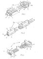
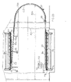
- the Etl head screens (FIGS. 1, 6, 7, 15, 16, 20 and 27), designed for group tensioning of the reinforcements and for enabling them to be cut after demolding, comprise on the one hand two front walls 1, according to the profile of the product to be manufactured and mounted relative to each other at a distance allowing said cutting, walls provided with holes for the passage of said frames and covers 2, (removable or fixed and provided with holes t for cutting frames), and reinforced with vertical ribs 3a, and / or horizontal 3b , in order to make them self-supporting both in relation to the tensioning forces and in relation to the prestressing forces, and on the other hand comprise means 4, for anchoring the reinforcements and means 5, for rapid attachment to the various devices in group tensioning, so that said screens, movable relative to the molds, facilitate the operations of setting up, tensioning and demolding, reduce the losses of reinforcements and can take charge of the prestressing efforts over time wanted after demolding.
- the head screens Et2 (FIG. 2), also designed for group tensioning, consist of a single part 6, in particular cast according to the profile of the product to be produced, a part provided with means 4 for anchoring, and hooking means 5, and provided in certain cases with holes and / or cavities t for cutting the reinforcements when this operation is necessary, so that said screens, movable relative to the molds, provide the same functional advantages as Etl screens.
- the head screens Et3, (FIGS. 3, 5, 17 and 26), designed for tensioning wire by wire of the reinforcements, include a resistance plate 7, self-supporting both with respect to the stressing forces and with respect to the prestressing efforts, plate provided on the one hand with means 4, for anchoring the reinforcements and a wall 8, according to the profile of the product to be produced, wall which penetrates inside the molds over a length ensuring rapid fixing and watertight and, in some cases, cutting the reinforcements through holes and / or cavities t, and on the other hand provided with means 9, for sloping sliding relative to the ends of the molds and means 10 (FIG.
- the Et4 head screens ( Figures 4, 9, 15 and 23), on the one hand, have the same type of frame for anchoring the frames as the Etl screens, but they have feet 9a, sliding in slope, intimately welded to said frame so that, by equipping said feet, with locking devices 10a, said screens are used for tensioning wire by wire of the reinforcements, ensure automatic demolding and so that by equipping said pieces with traction means 11, in particular by screwing, the screens Et4, can ensure on the one hand the group tensioning of the buttoned wires f and on the other hand the automatic demolding.
- the mobile and self-supporting separation screens Es (FIGS. 5 and 20), provided, in certain cases, with temporary fixing means relative to the molds, are constituted in the same way as the head screens, without obviously being provided with means anchoring and hanging.
- the devices for placing in a group MP comprise two or more arms 12, one of which is fixed 12a, and at least one sliding arm, carrier 12b, arms provided with tilting heads 13, and, for the arms 12b, of means 14, of long rolling molds so that, in the "tight arms” position (at one of the two ends of the molds), the screens are fixed using known means on said heads and the frames are threaded through said screens, blocking them on the screens fixed to the support arm and so that, in the "arms apart” position, the "screen-frames" assembly is tilted in the molds.
- the group tensioning devices by bias bias MT1 (FIGS. 6 and 7), comprise sliding axes 15, inside the sleeves 15a, fixed at an angle on the two ends of the self-supporting benches or self-supporting structures, using gussets 16, axes provided on the one hand with sleeves 17, ensuring the adjustable fixing of the means 18, for attaching the head screens, and on the other hand with means 19, ensuring the back and forth movement.
- the group tensioning devices by deformable parallelogram MT2 include a series of connecting rods 20, provided with hooking means 21, head screens, linked by ordinary articulations 22, to a series of connecting rods 20a , for fixing by articulation at the ends of the structure for taking charge of tensioning forces, and on the other hand for locking means 23, so that the assembly described works as a deformable parallelogram which, in the stretched position, is self-locking and which, by unlocking, ensures the slow relaxation of the armatures, facilitates demolding and frees the head screens which thus remain plated at the ends of the demolded products.
- the devices for tensioning by sliding in parallel MT3 include a few sliding doors 24, of high resistance, provided with hooking means 25, and locking means 26, head screens, and some parts. 27, sliding, beams linked by means of one or more rods 28, provided in particular with screwing means 29, to arms 30, fixed at the two ends of the benches or of the self-supporting structures, using removable means 31, so that, by the screwing operation of the rods, the tensioning is carried out in a group and so that, by unscrewing, the prestressing forces are taken over by said self-supporting screens which remain thus plated at the ends of the unmolded products.
- the MT4 tilting group tensioning devices ( Figures 20, 21, 27 and 28) include arms 32, mounted using pins 33, and two gussets 34, at the two ends of the self-supporting benches or self-supporting structures, arms fitted with beams 35, provided with means 36, for fixing to said arms, means 37, for attaching the head screens and means 38, for blocking said screens, so that, by tightening the arms using in particular tie rods 39, provided with means 40, screwing and means 41, for protection, the reinforcements are slowly and grouped under tension and so that, by loosening, the forces of tensioning in prestressing efforts supported by the same screens which remain pressed against the ends of the demolded products.
- the arms can be tilted 32, on the structures for taking charge of the tensioning forces, by means of available sitifs 42, allowing the bias to slide so as to facilitate the release of the products into packages.
- the Bal self-supporting benches (FIGS. 6, 7 and 8), designed for the manufacture of products with group tensioning, comprise on the one hand a framework for taking charge of the tensioning forces constituted in particular at using two main resistance beams 43, provided in certain cases with rails 44, for the distribution of the concrete and using a series of transverse beams 45, provided either with plates 46, for fixing the vibrators 47, or of parts 48, facilitating the attachment of the removable compacting means, and on the other hand one or more batteries of ordinary bm molds, mounted head to head by welding, either in a removable manner, so that said benches equipped with devices group tensioning, mobile and self-supporting screens and, in some cases, own rolling means 49, can be used with increased efficiency in "ground", "chain” and "rotary" processes.
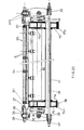
- the Ba2 self-supporting benches ( Figures 17, 18, 19, 25 and 26), designed in particular for the production of linear products with tensioning wire by wire, include on the one hand a series of beams for taking charge tensioning, formed using longitudinal beams 50, on which are welded two by two the side walls of the molds 51, linked in advance by a metal profile 52, beams transversely reinforced by the bottom of the molds 51a, and by beams 53, serving at the same time for fixing the compacting means, and provided with sloping sliding parts 54, so that, by equipping said benches with self-supporting screens, in particular of the Et3 or Et4 type, and in certain in the case of own rolling means 49, they can be used with increased efficiency "on the ground", "in chain” or by "rotation".
- the self-supporting benches Ba3, (FIGS. 9 and 10), designed for the manufacture of surface products (slabs, floors, etc.), include a framework 55, for taking charge of the tensioning forces covered with a smooth sheet metal 55a , and equipped in certain cases with own rolling means 49, framework provided with a series of niches 56, having the front walls 56a, sloping so as to be able to receive the head screens Et4, in a position fixed to one ends and in a variable position, depending on the length of the products, at the other end.
- Mobile and self-supporting screens, group placement and tensioning devices and self-supporting benches allow, according to the method described, to produce new mold-carrying structures and new shock heat treatment, mold release and cooling which improve the efficiency of the known processes for the manufacture of prestressed concrete products by adherent reinforcements.
- the self-supporting benches equipped with self-supporting screens and, in some cases, group tensioning devices, can be, in particular for small production units, fixed "to the ground” either head to head or side beside.
- the benches can be moved "in chain” either head to head, in particular on rollers, or side by side using own rolling means, or finally by rotation with vertical axis or horizontal axis.
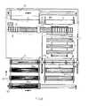
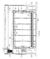
- FIG. 8 shows a chain equipped with benches of self-supporting molds provided with own rolling means, benches moving on rails in a manufacturing circuit, in horizontal plane, closed by means of two head ferries 57, so as to pass the molds filled with concrete and closed with covers C, through two adjacent chambers F1, of intensive heating in a tunnel and to present them at the demoulding station d, below an installation Dl, consisting either of an overhead crane, or in particular of a gantry 58, provided with a cantilever beam false 58a, and lifting and hooking means, which performs on the one hand the transfer of the covers between the demoulding station d and the introduction station i in the tunnel, and on the other hand the transfer of the demolded products to said tunnel where cooling r, finishing and evacuation are carried out successively e.
- an installation Dl consisting either of an overhead crane, or in particular of a gantry 58, provided with a cantilever beam false 58a, and lifting and hooking means, which performs on the one
- FIG. 10 a manufacturing circuit of the two-way "multi-purpose chain” type 59 is shown, superimposed in vertical plane, circuit equipped with self-supporting mold banks, in particular of the Ba3 type, and equipped with an installation shock thermal treatment comprising covers C, closing the molds and an intensive heating chamber-tunnel F2, and on the other hand means D2, for transferring said covers between the demoulding station d and the concreting station b, for demolding and transferring the demolded products p above said chamber F2, for cooling, so that by providing the concreting station with a device for introducing tubes 60, through the screens Et4, it is possible to compacting the concrete in two stages, the last of which is done "bench-closed", an operation which allows the extraction of said tubes, by traction combined with a few rotational movements in both directions, without danger of erasing the concrete during the extraction of tubes or after.
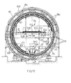
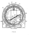
- FIGS. 11 and 12 a rotary chain with a vertical axis is shown, equipped on the one hand with self-supporting benches Ba4, in particular for the manufacture of poles for electric lines, and on the other hand provided with a rotary table 61, which passes, by its rotation step by step, said benches fixed on elastic pads 62, and closed with covers C, through towards a circular chamber F3, of intensive heating and presents them at the exit of the latter at the demolding station d, below an installation D3, which, using a rotary gantry with central pivot 63, and on the outside foot 63a, rolling on a circular rail 64, performs on the one hand the transfer of the covers between the stations d and i, and on the other hand the demolding and the transfer of the demolded products between said demolding station and the station cooling r, and between it and the evacuation station e.
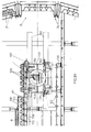
- FIGS. 13 and 14 show a rotary chain with a horizontal axis, provided with a fixed structure having two head gantries 65, equipped with circular guides 66, and connected on the one hand by the working platforms 67, and on the other hand by the walls 68, of the heating chamber F4, provided with heating means, in particular by infrared radiators 69, (electric or gas) so that the benches of molds Ba, equipped with own rolling means 70, and closed by means of covers C, are moved in a rotary circuit, a circuit which can be combined with demolding and cooling installations of the types described below for the "rotary hall" process.
- Another preferred embodiment example is that of the "rotary hall", improved both with regard to the support structure and with regard to the heat treatment, demolding and cooling installations (FIGS. 19, 20, 21, 22, 23 and 24).
- the arrangement of the two rings at the ends of the supporting structure makes it possible to produce a thermal shock installation using a series of metal covers C1, movable relative to the benches, and a chamber F4, of intensive heating, arranged in an arc of a circle between the concreting station b and the demolding station d (the latter, placed at 270 ° relative to the first), chamber provided on the one hand with a wall of heat treatment 81, placed to facilitate sealing between the two rings, wall having the upper part suspended from the roof 83 which, for its part, is placed using rollers 84, on the two rings, chamber equipped on the other hand intensive heating means either by steam 85 or by means of electric or gas infrared radiant heaters.
- the metal covers C1 (FIGS. 14, 17, 18, 19 and 21), closing in one piece each bench of molds between the concreting station and the demolding station, consist of a resistance framework on the one hand 86, covered with a smooth sheet 87, and are provided on the other hand with automatic hooking-detaching means 88, on said benches by means of locking pieces 89, so that the transfer of said covers, between the demoulding station d and the concreting station b, is carried out using the demoulding installation D on the one hand, and using a short chain 90, on the other hand, and a rolling beam 91, which releases said chain and descends the covers in the vertical axis of the hall by hanging them on the bench located at the concreting station.
- the mold banks are closed using several covers C2 (FIGS. 23 and 24), made up of a smaller frame 86a, also covered by a smooth sheet 87, and provided with rollers 92, so that by fixing pieces 93 on the benches, with the head sloping, it is possible to block said covers on the bench filled at the concreting station by pushing them against each other, and so that the release and the return of the covers takes place automatically using an installation, placed in particular in the vertical plane of the hall, comprising a tilting device 94, equipped with a jack 95, linked to a rod with vertical fingers 95a, which, at each stop of the hall, unlocks said covers and deposits them by tilting it over two guide rails 96, mounted on a slope 96a, at the release station and in a loop 96b, between the latter and the concreting station, loop fixed by reinforcements 82a, and provided with oiling 97, and braking 98, so that once said loop filled with covers, these simply descend by gravity, arriving either directly in a
- the demoulding installation D4 comprises on the one hand a framework, in particular tubular 100, provided with two head walls 101, means 102, back and forth, relative to the mold bank located at the demoulding station and rotation means 103, it also comprises means 104, unlocking and 105, for fitting covers C, on the chain of return 90, means 106, for demolding in a package and means 107, for transferring the demolded products, whether or not provided with self-supporting screens in front of the entrance to the various cooling installations and, in certain cases, it also includes means for cleaning and oiling of molds.
- the cooling installations R used in particular for the "rotary hall” and for the “rotary drum”, are designed horizontally R1, on a slope R2, or by rotation R3.
- the installation Rl (FIGS. 14 and 19), arranged horizontally between the demoulding station d, and that of evacuation e, comprises on the one hand a support floor 108, and an enclosure provided with a ceiling 109, two head walls 110, and some closure membranes 111, and furthermore comprises means for step by step transfer of the demolded products, in particular using channels 112.
- the R2 installation ( Figures 21, 22 and 23), arranged on a slope inside or outside the "rotating hall", comprises on the one hand a support frame 113, two main walls of thermal insulation 114, two head walls 115, closing membranes 111, and a few sliding beams 116, and on the other hand comprises a device 117, for introducing and pushing cured products at the top and a device 118, for receiving in bottom and transfer of said products to the finishing line.
- the installation R3, (FIG. 25), comprises on the one hand an independent support frame 119, provided with a chamber 120, in particular circular, with thermal insulation walls 121, inside which rotates, at the using a device 122, of step-by-step rotation, a cylinder 123, provided with a few removable niches 124, having the outline of the demolded products, products which are thus transferred between the demoulding installation D, and the chain of evacuation e, with progressive cooling.
- the method according to the invention allows on the one hand either to equip the ordinary rotary structure with self-supporting benches of molds, or to produce a new structure, self-supporting itself with respect to the forces of tensioning, and on the other hand to provide said process with new installations so as to be able to produce fixed or mobile units by land or sea, improving the manufacture of prestressed concrete products.
- Figures 27 and 28 show a structure self-supporting rotary, consisting of an axial beam 126, of support and rotation, linked by two head walls 127, and by some radial bracing elements 128, to a series of peripheral beams 129, for taking charge of the forces of tensioning, beams also braced in a circular direction, using the elements 130, and equipped on the one hand either with self-supporting screens Et4, or with tensioning devices in group MT4, and with ordinary mold batteries bm, fitted with self-supporting screens And, and also equipped with a shock thermal treatment installation comprising tilting covers C3, fixed to the structure or to the batteries, a series of intensive heating chambers F5, nested in the within said structure, and a rotating device 131, steam supply, so that said structure constitutes the centerpiece of factory to a fixed, movable or floating in the manufacture of prestressed concrete products.
- a shock thermal treatment installation comprising tilting covers C3, fixed to the structure or to the batteries, a series of intensive heating chambers F5,
- a final example of embodiment is that of a floating plant of the "rotating drum" type (FIGS. 25 and 26), comprising either a self-supporting structure equipped with batteries of ordinary molds, provided with tilting C3 lids, for closure, or a structure non-load-bearing 132, equipped with self-supporting benches also equipped with tilting closing lids, structures mounted using two a-pui and rotation devices 133, in a hull 134, in particular in reinforced concrete, hull provided on the one hand with some consoles 135, for mounting and with two walls 136, for supporting said structures and for transverse reinforcement, shell provided on the other hand with a metal frame having the lower part 137, securely fixed to its walls and the upper part 138, removable or even sliding in the lower part, in order to reduce the height during transport so that by equipping with a from the said plant, a device for setting up an MP group, a concreting installation with a fixed buffer hopper 139, and with a mobile distribution hopper 140, a chamber F6, intensive heating and an installation
Abstract
Méthode selon laquelle on utilise des ecrans de têtes mobiles et autoportants (Et) pour la fermeture des moules (m) aux deux extrémités et pour l'ancrage des armatures (a); on réalise le démoulage des produits avec transfert des efforts de précontrainte aux écrans de tête, puis lorsque le béton a acquis une résistance supplémentaire par rapport à celle existant au moment du démoulage, on réalise le transfert des efforts de précontrainte au béton par adhérence et on récupère les écrans autoportants (Et).Method according to which mobile and self-supporting head screens (Et) are used for closing the molds (m) at both ends and for anchoring the frames (a); the products are demolded with transfer of the prestressing forces to the head screens, then when the concrete has acquired an additional resistance compared to that existing at the time of demolding, the prestressing forces are transferred to the concrete by adhesion and recovers freestanding screens (And).
Description
L'invention est relative à une méthode, à des dispositifs, à des structures porteuses de moules et à des installations permettant d'améliorer l'efficacité des procédés pour la fabrication des produits en béton précontraint par armatures adhérentes.The invention relates to a method, to devices, to mold-carrying structures and to installations making it possible to improve the efficiency of the processes for the production of prestressed concrete products by adherent reinforcements.
On sait que la fabrication des produits en béton précontraint impose souvent le coulage et le durcissement du béton dans les moules et une exigence particulière pour les opérations de mise en place, mise en tension et en détension des armatures (fils ou torons).It is known that the production of prestressed concrete products often imposes the pouring and hardening of concrete in the molds and a particular requirement for the operations of placing, tensioning and relaxing the reinforcements (wires or strands).
De ce fait, l'efficacité de n'importe quel procédé pour la fabrication des éléments en béton précontraint est déterminée principalement par le cycle d'utilisation des moules et par des moyens utilisés pour la mise en place, la mise en tension et la détension des armatures.Therefore, the effectiveness of any process for the manufacture of prestressed concrete elements is mainly determined by the cycle of use of the molds and by means used for the establishment, tensioning and expansion reinforcements.
Dans les procédés dits "bancs au sol", les moules sont utilisés une seule fois par jour, ce qui rend inefficace l'exploitation industrielle de ces procédés.In the so-called "ground benches" processes, the molds are used only once a day, which makes industrial exploitation of these processes ineffective.
Les procédés "en chaine" arrivent à utiliser les moules jusqu'à deux fois par jour mais, du fait que lesdits moules ont la largeur du produit à fabriquer, les opérations de mise en place, mise en tension et détension des armatures sont laborieuses, surtout pour des produits courts.The "chain" processes manage to use the molds up to twice a day but, since the said molds have the width of the product to be produced, the operations of placing, tensioning and relaxing the reinforcements are laborious, especially for short products.
Le procédé "chaine à flotteurs", qui dispose de certaines facilités pour le durcissement du béton, n'a été doté à ce jour de moyens pour la fabrication d'éléments en béton précontraint.The "float chain" process, which has certain facilities for hardening concrete, has so far been provided with means for the production of prestressed concrete elements.
Les procédés "hall rotatif" et "tambour rotatif" ont des réserves encore non exploitées tant pour la rotation rapide des moules que pour les divers processus technologiques.The "rotary hall" and "rotary drum" processes have still unexploited reserves both for the rapid rotation of the molds and for the various technological processes.
L'invention a pour but de mettre à la disposition de ces procédés une méthode, des dispositifs, des structures porteuses des moules et des installations permettant d'améliorer leur efficacité.The object of the invention is to provide these methods with a method, devices, mold-carrying structures and installations making it possible to improve their efficiency.
Selon l'invention, la méthode d'amélioration de l'efficacité des procédés de fabrication, ci-avant cités, utilise des écrans mobiles et autoportants, des dispositifs de mise en place et de mise en tension en groupe, de nouvelles structures porteuses des moules et des installations de durcissement du béton et de démoulage qui d'une part simplifient les processus technologiques respectifs et assurent une diminution non-négligeable des pertes d'armatures (fils ou torons) et qui d'autre part permettent de devancer, dans certains cas, le démoulage en transférant par l'intermédiaire desdits écrans la force de précontrainte au bout des éléments et de continuer le durcissement des éléments démoulés encore une période après laquelle, le béton ayant une résistance accrue, le transfert de la précontrainte par adhérence entre armatures et béton devient plus efficace.According to the invention, the method for improving the efficiency of the manufacturing processes, mentioned above, uses mobile and self-supporting screens, group positioning and tensioning devices, new load-bearing structures. molds and concrete hardening and demoulding installations which on the one hand simplify the respective technological processes and ensure a non-negligible reduction in losses of reinforcements (wires or strands) and which on the other hand allow to advance, in certain case, demolding by transferring via said screens the prestressing force at the end of the elements and to continue hardening of the demolded elements still a period after which, the concrete having an increased resistance, the transfer of the prestressing by adhesion between reinforcements and concrete becomes more efficient.
Selon l'invention, les dispositifs, les structures porteuses et les installations, permettant d'améliorer l'efficacité des divers procédés de fabrication des produits en béton précontraint, consistent principalement en :
- - écrans de tête, mobiles par rapport aux moules et autoportants par rapport aux efforts de mise en tension et de précontrainte
- - écrans de séparation, mobiles et autoportants ;
- - dispositifs de mise en place en groupe des armatures ;
- - dispositifs de mise en tension en groupe des armatures, par coulissement en biais par rapport aux moules ;
- - dispositifs de mise en tension en groupe par parallélogramme déformable ;
- - dispositifs de mise en tension en groupe par. glissement en parallèle ;
- - dispositifs de mise en tension en groupe par basculement ;
- - bancs de moules, fixes ou mobiles, autoportants par rapport aux efforts de mise en tension, dotés d'écrans mobiles autoportants et, dans certains cas, de' dispositifs de mise en tension en groupe ;
- - structures porteuses de moules équipées d'un ou plusieurs moyens décrits ci-avant ;
- - installations de traitement thermique de choc dotées de couvercles notamment métalliques et de chambres de chauffage intensif ;
- - installations de transfert des couvercles par gravitation ;
- - installations de démoulage à fonctions multiples : transfert des couvercles, démoulage en paquet, transfert des produits démoulés et, dans certains cas, nettoyage et huilage ;
- - installation de refroidissement des produits démoulés.
- - head screens, movable with respect to molds and self-supporting with respect to tensioning and prestressing efforts
- - separation screens, mobile and freestanding;
- - devices for grouping reinforcement;
- - group tensioning devices for reinforcements, by sliding at an angle to the molds;
- - group tensioning devices by deformable parallelogram;
- - group tensioning devices par. sliding in parallel;
- - group tensioning devices by tilting;
- - mold benches, fixed or mobile, self-supporting with respect to tensioning efforts, provided with self-supporting mobile screens and, in some cases, 'group tensioning devices;
- - mold-carrying structures equipped with one or more means described above;
- - shock thermal treatment installations with covers, in particular of metal, and intensive heating chambers;
- - gravity lids transfer facilities;
- - multipurpose demolding installations: transfer of covers, demoulding in packages, transfer of demolded products and, in some cases, cleaning and oiling;
- - cooling installation for demolded products.
De préférence, les écrans de tête pour la mise en tension en groupe des armatures, mobiles par rapport aux moules, comportent d'une part soit deux parois suivant le profil du produit à fabriquer, renforcées à l'aide de nervures afin de les rendre autoportantes par rapport aux efforts de mise en tension et par rapport aux efforts de précontrainte, soit une seule pièce autoportante par rapport auxdits efforts et d'autre part des moyens d'ancrage des armatures et des moyens permettant leur accrochage rapide sur les divers dispositifs de mise en tension en groupe de manière que, pourvus de trous pour le passage des armatures, lesdits écrans facilitent les opérations de mise en place, mise en tension et démoulage, assurent la réduction des pertes d'armatures et prennent en charge les efforts de précontrainte le temps voulu, après démoulage.Preferably, the head screens for the group tensioning of the reinforcements, movable relative to the molds, have on the one hand either two walls according to the profile of the product to be produced, reinforced with ribs in order to make them self-supporting with respect to the tensioning forces and with respect to the prestressing forces, that is to say a single self-supporting part with respect to said forces and on the other hand means for anchoring the reinforcements and means allowing their rapid attachment to the various devices of group tensioning so that, provided with holes for the passage of the reinforcements, said screens facilitate the operations of setting up, tensioning and demolding, ensuring the reduction of reinforcement losses and taking charge of the prestressing efforts for the required time, after demolding.
Dans le cas de mise en tension fil par fil des armatures, les écrans de tête sont constitués d'une ossature autoportante par rapport aux efforts de mise en tension et de précontrainte, ossature dotée d'une part de moyens d'ancrage des armatures et d'une paroi suivant le produit à fabriquer et d'autre part de moyens de glissement en pente par rapport aux extrémités des moules et de moyens de blocage par rapport à celles-ci de manière que d'une part lesdits écrans permettent d'automatiser l'opération de démoulage et de manière que d'autre part ils facilitent la mise en place, réduisent les pertes d'armatures et prennent en charge les efforts de précontrainte après démoulage.In the case of tensioning wire by wire of the reinforcements, the head screens consist of a self-supporting framework with respect to the stressing and prestressing forces, framework provided on the one hand with means for anchoring the reinforcements and of a wall according to the product to be produced and on the other hand of sloping sliding means relative to the ends of the molds and of locking means relative thereto so that on the one hand said screens make it possible to automate the demolding operation and so that, on the other hand, they facilitate installation, reduce the losses of reinforcements and take charge of the prestressing forces after demolding.
De préférence, les écrans mobiles et autoportants de séparation sont constitués de la même façon que les écrans de tête, n'étant pas dotés de moyens d'accrochage et de glissement, mais dans certains cas de moyens de blocage temporaires à l'intérieur des moules.Preferably, the mobile and self-supporting separation screens are constituted in the same way as the head screens, not being fitted with means for hooking and sliding, but in certain cases with temporary blocking means inside the mussels.
De préférence, les dispositifs de mise en place en groupe des armatures comportent plusieurs bras, à tête basculante, dont l'un fixe et l'autre ou les autres mobiles au long des moules de manière que, dans la position "bras serrés" (à l'une des deux extrémités des moules), on fixe les écrans, autoportants ou non, sur lesdites têtes, et on enfile les armatures à travers lesdits écrans et de manière que, dans la position "bras écartés", on bascule l'ensemble "écrans-armatures" dans les moules.Preferably, the devices for placing the reinforcements in a group comprise several arms, with tilting head, one of which is fixed and the other or the other are movable along the molds so that, in the "arms tight" position ( at one of the two ends of the molds), the screens are fixed, freestanding or not, on said heads, and the frames are threaded through said screens and so that, in the "arms apart" position, the set "screen-frames" in the molds.
Avantageusement, les dispositifs de mise en tension en groupe par coulissement en biais par rapport aux moules comportent des axes coulissant à l'intérieur des manchons, ceux-ci se trouvant fixés en biais aux extrémités de la structure de prise en charge de la force de mise en tension, axes dotés de moyens d'accrochage des écrans de tête et de moyens de coulissement, de manière que, par leur rapprochement par rapport aux moules, ils assurent la détension lente des armatures, facilitent le démoulage en paquet et libèrent les écrans de tête qui restent plaqués aux extrémités des produits démoulés.Advantageously, the group tensioning devices by sliding at an angle with respect to the molds have axes sliding inside the sleeves, the latter being fixed at an angle to the ends of the structure for taking charge of the tensioning force, axes provided with means for hooking the head screens and for sliding means, so that, by their approximation relative to the molds, they ensure slow expansion frames, facilitate demoulding in a package and free the head screens which remain pressed against the ends of the demolded products.
De préférence, les dispositifs de mise en tension en groupe par parallèlogramme déformable comportent d'une part une série de bielles dotées de moyens d'accrochage des écrans de tête, liées par articulations ordinaires à une série de bielles de fixation par articulations aux extrémités de la structure de prise en charge des efforts de mise en tension, et d'autre part des moyens de blocage de manière que l'ensemble décrit travaille comme un parallélogramme déformable qui, en position tendue, s'autoverrouille et qui, par déverrouillage, assure la détension lente des armatures, facilite le démoulage et libère les écrans de tête qui sortent ainsi plaqués aux extrémités des produits démoulés.Preferably, the group tensioning devices by deformable parallelogram comprise on the one hand a series of connecting rods provided with means for hooking the head screens, linked by ordinary articulations to a series of connecting rods by articulation at the ends of the structure for taking charge of the tensioning forces, and on the other hand the locking means so that the assembly described works as a deformable parallelogram which, in the stretched position, is self-locking and which, by unlocking, ensures the slow tensioning of the frames, facilitates demolding and frees the head screens which come out pressed against the ends of the demolded products.
De préférence, les dispositifs de mise en tension en groupe par glissement en parallèle par rapport aux moules comportent d'une part des bras dotés de moyens de fixation sur les deux estrémités de la structure de prise en charge de la force de mise en tension, et d'autre part des poutres glissantes pourvues de moyens d'accrochage des écrans de tête et de tiges pour la mise en tension.Preferably, the group tensioning devices by sliding in parallel with respect to the molds comprise on the one hand arms provided with fixing means on the two ends of the structure for taking charge of the tensioning force, and on the other hand sliding beams provided with means for hooking the head screens and rods for tensioning.
Avantageusement, les dispositifs de mise en tension en groupe par basculement comportent d'une part des bras dotés de moyens de basculement, montés aux deux extrémités de la structure de prise en charge de la force de mise en tension, et d'autre part des poutres de résistance pourvues de moyens de fixation aux bras basculants, de moyens d'accrochage des écrans de tête et de moyens de blocage desdits écrans. Dans certains cas, lorsque la détension des armatures est appelée à aider la sortie des produits hors des moules, on monte lesdits bras basculants sur les têtes de la structure porteuse par l'intermédiaire d'appareils de glissement en biais.Advantageously, the group tensioning devices by tilting comprise on the one hand arms provided with tilting means, mounted at the two ends of the structure for taking charge of the tensioning force, and on the other hand resistance beams provided with means for fixing to the tilting arms, means for hanging the head screens and means for blocking said screens. In certain cases, when the slackening of the reinforcements is called upon to aid the exit of the products from the molds, said rocking arms are mounted on the heads of the support structure by means of biasing devices.
De préférence, les bancs de moules autoportants comportent une ossature métallique garnie de coquilles, capable de prendre en charge les efforts de mise en tension, équipée d'écrans mobiles et autoportants et, dans certains cas, de dispositifs de mise en tension en groupe, ossature pouvant être dotée de moyens de roulement.Preferably, the self-supporting mold banks have a metal frame furnished with shells, capable of taking charge of the tensioning efforts, equipped with mobile and self-supporting screens and, in certain cases, group tensioning devices, frame can be provided with rolling means.
Les écrans mobiles et autoportants, les dispositifs de mise en place et de mise en tension en groupe et les bancs de moules autoportants, ci-avant décrits, permettent d'améliorer d'une part les structures porteuses des moules et d'autre part les installations de durcissement du béton et de démoulage des divers procédés.The mobile and self-supporting screens, the group setting-up and tensioning devices and the self-supporting benches of molds, described above, make it possible to improve on the one hand the supporting structures of the molds and on the other hand the concrete hardening and demoulding installations for various processes.
Ainsi, les bancs de moules autoportants d'une certaine longueur peuvent être soit fixés au sol, soit notamment déplacés dans des circuits de fabrication "en chaine" de type ordinaire ou de type utilisant la rotation.Thus, the self-supporting mold banks of a certain length can either be fixed to the ground, or in particular moved in manufacturing circuits "in chain" of ordinary type or of type using rotation.
Pour le procédé "chaine à flotteurs", on peut réaliser des structures flottantes autoportantes par rapport aux efforts de mise en tension, dotées de dispositifs de mise en tension en groupe et équipées soit d'une plate-forme lisse, soit de batteries de moules dotées d'écrans mobiles et autoportants.For the "float chain" process, self-supporting floating structures can be produced with respect to the tensioning forces, provided with group tensioning devices and equipped either with a smooth platform or with mold batteries. with mobile and self-supporting screens.
Pour les procédés "hall rotatif" et "tambour rotatif", procédés utilisant la rotation à axe horizontal, la méthode et les divers dispositifs permettent de réaliser des nouvelles structures porteuses qui passent les bancs de moules autoportants ou des batteries de moules ordinaires à travers une installation de traitement thermique de choc et les présentent face à une installation de démoulage à fonctions multiples, de manière que les produits démoulés en paquet, munis dans certains cas d'écrans autoportants, soient transférés à travers une chambre de refroidissement sur une chaine d'évacuation où peuvent être récupérés les écrans autoportants.For the "rotary hall" and "rotary drum" processes, processes using rotation with a horizontal axis, the method and the various devices make it possible to produce new load-bearing structures which pass the banks of self-supporting molds or bats ries of ordinary molds through a shock heat treatment installation and present them facing a multi-function demolding installation, so that the products demoulded in a package, provided in some cases with self-supporting screens, are transferred through a chamber cooling on an evacuation chain where freestanding screens can be recovered.
L'invention consiste, mises à part les dispositions exposées ci-dessus, en certaines autres dispositions dont il sera explicitement question ci-après, à propos de plusieurs exemples préférentiels de réalisation décrits avec référence aux dessins ci-annexés, mais qui ne sont nullement limitatifs.
- - La figure 1 de ces dessins est une vue en perspective des écrans, mobiles et autoportants, conçus pour la mise en tension en groupes des armatures et pour permettre la coupure de celles-ci après démoulage.
- - La figure 2 est une vue en perspective des écrans, mobiles et autoportants, conçus d'une seule pièce pour la mise en tension en groupe des armatures avec ou sans la coupe finale de celles-ci.
- - La figure 3 est une vue en perspective de deux écrans de tête, mobiles et autoportants, conçus pour la mise en tension fil par fil des armatures.
- - La figure 4 est une coupe longitudinale d'une structure autoportante dotée d'écrans de tête, mobiles et autoportants, conçus de manière à servir d'une part à la mise en tension fil par fil et de manière à réaliser, dans certains cas, la mise en tension en groupe par rangée de moules.
- - La figure 5 est une vue en perspective d'un dispositif de mise en place en groupe des armatures à l'aide desdits écrans autoportants.
- - La figure 6 est une coupe longitudinale à travers un banc de moules autoportants, doté d'une part d'écrans autoportants et de dispositifs de mise en tension en groupe par coulissement en biais et d'autre part, dans certains cas, de moyens propres de roulement.
- - La figure 7 est une coupe transversale suivant 1-1 (figure 6) à travers ledit banc autoportant.
- - La figure 8 est une vue en plan d'une chaîne équipée de bancs de moules autoportants et d'une installation de traitement thermique de choc.
- - La figure 9 est une coupe longitudinale à travers un banc autoportant pour la fabrication de dalles alvéolées, doté d'écrans autoportants pour la mise en tension fil par fil.
- - La figure 10 est une coupe à travers un circuit de fabrication du type "chaine polyvalente" équipé de bancs autoportants selon la figure 9.
- - La figure 11 est une coupe longitudinale à travers un banc de moules autoportant, conçu pour la fabrication de poteaux pour lignes électriques, banc doté d'écrans autoportants de mise en tension en groupe et monté sur une chaine à axe vertical.
- - La figure 12 est une vue en plan d'une chaine rotative, à axe vertical, équipée de bancs de moules autoportants, selon la figure 11, et dotée d'une installation de traitement thermique de choc.
- - La figure 13 est une coupe longitudinale à travers un banc de moules autoportant, doté d'écrans autoportants et de dispositifs de mise en tension en groupe par parallélogramme déformable, banc doté de moyens propres de roulement et monté sur une structure permettant son déplacement selon un circuit du type "hall rotatif".
- - La figure 14 est une coupe transversale d'une chaine rotative à axe horizontal, équipée de bancs de moules autoportants et dotée des installations du type utilisé dans le procédé "hall rotatif".
- - La figure 15 est une coupe longitudinale à travers une structure flottante autoportante, dotée de dispositifs de mise en tension en groupe, notamment par coulissement en parallèle, et d'une plate-forme lisse montée sur des plots élastiques et équipée d'écrans autoportants.
- - La figure 16 est une coupe transversale suivant I-I (figure 15) à travers ladite structure flottante.
- - La figure 17 est une coupe longitudinale à travers un banc de moules autoportant,, doté d'écrans autoportants pour la mise en tension fil par fil des armatures, banc équipé d'un couvercle métallique enfermant le béton dans les moules.
- - La figure 18 est une coupe transversale suivant I-I (figure 17) à travers ledit banc autoportant.
- - La figure 19 est une coupe transversale d'un "hall rotatif" doté d'une part d'une structure rotative équipée de bancs de moules autoportants (figures 17 et 18), et doté d'autre part d'un dispositif de mise en place en groupe d'une installation de traitement thermique de choc à la vapeur, d'une installation de démoulage à fonctions multiples et d'une installation de refroidissement disposée à l'horizontale.
- - La figure 20 est une coupe longitudinale à travers une structure rotative du type "hall rotatif", autoportante par rapport aux efforts de mise en tension, structure dotée de dispositifs de mise en tension en groupe par basculement et équipée de batteries de moules ordinaires dotées d'écrans autoportants.
- - La figure 21 est une coupe transversale d'un "hall rotatif", doté d'une part de ladite structure autoportante (figure 20), et d'autre part d'une installation de traitement thermique de choc, d'une installation de démoulage à fonctions multiples et d'une installation de refroidissement disposée en pente à l'extérieur.
- - La figure 22 est une coupe transversale de l'installation de refroidissement disposée en pente à l'extérieur du "hall rotatif" (figure 21).
- - La figure 23 est une coupe longitudinale d'un "hall rotatif" doté d'une part d'une structure équipée elle-même d'écrans autoportants de mise en tension fil par fil et d'autre part d'une installation de transfert des couvercles par gravitation et d'une installation de refroidissement en pente disposée à l'intérieur du hall.
- - La figure 24 est une coupe transversale du "hall rotatif" (figure 23).
- - La figure 25 est une coupe transversale d'un "tambour rotatif flottant" équipé de bancs de moules autoportants, selon l'une des solutions décrites ci-avant, et doté d'un dispositif de mise en place en groupe, d'une installation de traitement thermique de choc à couvercles basculants, d'une installation de démoulage à fonctions multiples et d'une installation rotative de refroidissement.
- - La figure 26 est une coupe longitudinale à travers le "tambour rotatif" (figure 25).
- - La figure 27 est une coupe transversale d'une structure du type "tambour rotatif", autoportants par rapport aux efforts de mise en tension, structure dotée principalement de dispositifs de mise en tension en groupe par basculement et d'une installation de traitement thermique de choc incorporée.
- - La figure 28 est une coupe longitudinale à travers la structure ci-dessus (figure 24).
- - La figure 29 est une coupe transversale à travers l'installation de démoulage à fonctions multiples.
- - Figure 1 of these drawings is a perspective view of screens, mobile and self-supporting, designed for the tensioning in groups of the frames and to allow the cutting thereof after demolding.
- - Figure 2 is a perspective view of screens, mobile and self-supporting, designed in one piece for the group tensioning of the frames with or without the final cut thereof.
- - Figure 3 is a perspective view of two head screens, mobile and self-supporting, designed for tensioning wire by wire of the frames.
- - Figure 4 is a longitudinal section of a self-supporting structure with head screens, mobile and self-supporting, designed so as to serve on the one hand for the tensioning wire by wire and so as to achieve, in some cases , group tensioning by row of molds.
- - Figure 5 is a perspective view of a device for grouping the reinforcement using said self-supporting screens.
- - Figure 6 is a longitudinal section through a bench of self-supporting molds, provided with screens self-supporting and group tensioning devices by sliding at an angle and on the other hand, in certain cases, own rolling means.
- - Figure 7 is a cross section along 1-1 (Figure 6) through said self-supporting bench.
- - Figure 8 is a plan view of a chain equipped with self-supporting mold banks and a thermal shock treatment installation.
- - Figure 9 is a longitudinal section through a self-supporting bench for the manufacture of honeycomb slabs, with self-supporting screens for tensioning wire by wire.
- FIG. 10 is a section through a manufacturing circuit of the "multipurpose chain" type equipped with self-supporting benches according to FIG. 9.
- - Figure 11 is a longitudinal section through a self-supporting bench of molds, designed for the manufacture of poles for power lines, bench with self-supporting screens for group tensioning and mounted on a chain with vertical axis.
- - Figure 12 is a plan view of a rotary chain, with a vertical axis, equipped with self-supporting mold banks, according to Figure 11, and provided with a thermal shock treatment installation.
- - Figure 13 is a longitudinal section through a bench of self-supporting molds, with self-supporting screens and group tensioning devices by deformable parallelogram, bench with own rolling means and mounted on a structure allowing its movement according a "rotary hall" type circuit.
- - Figure 14 is a cross section of a rotatable chain with horizontal axis, equipped with mussel beds self p ortants and with installations of the type used in the process "rotary hall".
- - Figure 15 is a longitudinal section through through a self-supporting floating structure, equipped with group tensioning devices, in particular by sliding in parallel, and with a smooth platform mounted on elastic pads and equipped with self-supporting screens.
- - Figure 16 is a cross section along II (Figure 15) through said floating structure.
- - Figure 17 is a longitudinal section through a self-supporting bench of molds, with self-supporting screens for tensioning wire by wire of the frames, bench equipped with a metal cover enclosing the concrete in the molds.
- - Figure 18 is a cross section along II (Figure 17) through said self-supporting bench.
- - Figure 19 is a cross section of a "rotary hall" with on the one hand a rotary structure equipped with self-supporting mold banks (Figures 17 and 18), and on the other hand with a setting device in place as a group of a thermal shock treatment steam installation, a multi-function demolding installation and a cooling installation arranged horizontally.
- FIG. 20 is a longitudinal section through a rotary structure of the "rotary hall" type, self-supporting with respect to the tensioning forces, structure provided with group tensioning devices by tilting and equipped with ordinary mold batteries provided with freestanding screens.
- - Figure 21 is a cross section of a "rotary hall", provided on the one hand with said self-supporting structure (FIG. 20), and on the other hand with an impact heat treatment installation, with an installation for multipurpose demoulding and a cooling installation sloping outside.
- - Figure 22 is a cross section of the cooling installation arranged on a slope outside the "rotating hall" (Figure 21).
- - Figure 23 is a longitudinal section of a "rotating hall" provided on the one hand with a structure itself equipped with self-supporting screens for tensioning wire by wire and on the other hand with a transfer installation gravitational covers and a sloping cooling system located inside the hall.
- - Figure 24 is a cross section of the "rotating hall" (Figure 23).
- - Figure 25 is a cross section of a "floating rotating drum" equipped with self-supporting mold banks, according to one of the solutions described above, and provided with a device for group placement, a installation for shock heat treatment with tilting covers, a multi-function demolding installation and a rotary cooling installation.
- - Figure 26 is a longitudinal section through the "rotary drum" (Figure 25).
- - Figure 27 is a cross section of a structure of the "rotary drum" type, self-supporting with respect to the tensioning forces, structure provided mainly with group tensioning devices by tilting and a heat treatment installation shock incorporated.
- - Figure 28 is a longitudinal section through the above structure (Figure 24).
- - Figure 29 is a cross section through the multi-function demolding installation.
La méthode, objet de l'invention, utilise des écrans mobiles et autoportants Et, de fermeture des moules m aux deux extrémités et d'ancrage des armatures a (fils ou torons), des écrans mobiles et autoportants de séparation Es, des dispositifs de mise en place en groupe MP, des dispositifs de mise en tension en groupe MT, à l'aide desquels on peut soit réaliser des bancs de moules autoportants Ba, soit équiper directement certaines structures porteuses des moules de manière à améliorer d'une part les processus technologiques de mise en place, mise en tension et détension avec en même temps la réduction des pertes d'armatures et de manière à réaliser d'autre part de nouvelles structures porteuses de moules, équipées de bancs de moules autoportants ou de batteries de moules bm ordinaires, structures qui passent les moules à travers une installation de traitement thermique de choc utilisant des couvercles C (figure 8), notamment métalliques, pour la fermeture des moules et une chambre fixe F, suivant la trajectoire des moules, dotée de moyens de chauffage intensif, au bout de laquelle une installation à fonctions multiples D, décroche et transfère lesdits couvercles, réalise dans un deuxième temps le démoulage des produits P, en paquet, avec transfert lent des efforts de précontrainte aux écrans de tête et effectue dans un troisième temps la pose des produits démoulés, munis desdits écrans, devant une installation de refroidissement R, de manière que, après le passage desdits produits à travers cette dernière installation, ils arrivent sur une chaine d'évacuation où l'on récupère les écrans autoportants et on réalise ainsi le transfert des efforts de précontrainte au béton par adhérence, celui-ci ayant acquis une résistance supplémentaire par rapport à celle existant au démoulage.The method which is the subject of the invention uses mobile and self-supporting screens And, for closing the m molds at both ends and for anchoring the reinforcements to (wires or strands), mobile and self-supporting screens of separation Es, devices for setting up in group MP, devices for tensioning in group MT, using which one can either make benches of self-supporting molds Ba, or directly equip certain supporting structures of molds to improve on the one hand the technological processes of setting up, tensioning and relaxation with at the same time the reduction of losses of reinforcements and so as to realize on the other hand new structures carrying molds, equipped with benches of self-supporting molds or ordinary bm mold batteries, structures which pass the molds through an impact heat treatment installation using covers C (FIG. 8), in particular metal, for closing the molds and a fixed chamber F, along the path molds, with intensive heating means, at the end of which a multi-function installation D, unhooks and transfers said covers, produces in a second te mps the release of the products P, in a package, with slow transfer of the prestressing forces to the head screens and then performs the installation of the demolded products, fitted with said screens, in front of a cooling installation R, so that, after the passage of said products through this last installation, they arrive on a discharge chain where the self-supporting screens are recovered and the transfer of the prestressing forces to the concrete is thus carried out by adhesion, the latter having acquired an additional resistance compared to to that existing at demolding.
Les écrans de tête Etl, (figures 1, 6, 7, 15, 16, 20 et 27), conçus pour la mise en tension en groupe des armatures et pour permettre la coupure de celles-ci après démoulage, comportent d'une part deux parois frontales 1, suivant le profil du produit à fabriquer et montées l'une par rapport à l'autre à une distance permettant ladite coupure, parois pourvues de trous pour le passage desdites armatures et des couvercles 2, (démontables ou fixes et pourvus de trous t pour la coupure des armatures), et renforcées à l'aide de nervures verticales 3a, ou/et horizontales 3b, afin de les rendre autoportantes tant par rapport aux efforts de mise en tension que par rapport aux efforts de précontrainte, et comportent d'autre part des moyens 4, d'ancrage des armatures et des moyens 5, d'accrochage rapide aux divers dispositifs de mise en tension en groupe, de manière que lesdits écrans, mobiles par rapport aux moules, facilitent les opérations de mise en place, mise en tension et démoulage, diminuent les pertes d'armatures et puissent prendre en charge les efforts de précontrainte le temps voulu après le démoulage.The Etl head screens (FIGS. 1, 6, 7, 15, 16, 20 and 27), designed for group tensioning of the reinforcements and for enabling them to be cut after demolding, comprise on the one hand two
Les écrans de tête Et2, (figure 2), conçus eux aussi pour la mise en tension en groupe, sont constitués d'une seule pièce 6, notamment coulée suivant le profil du produit à fabriquer, pièce dotée de moyens 4 d'ancrage, et de moyens 5 d'accrochage, et pourvue dans certains cas de trous et/ou cavités t pour la coupure des armatures lorsque cette opération est nécessaire, de manière que lesdits écrans, mobiles par rapport aux moules, assurent les mêmes avantages fonctionnels que les écrans Etl.The head screens Et2 (FIG. 2), also designed for group tensioning, consist of a single part 6, in particular cast according to the profile of the product to be produced, a part provided with
Les écrans de tête Et3, (figures 3, 5, 17 et 26), conçus pour la mise en tension fil par fil des armatures, comportent une plaque de résistance 7, autoportante tant par rapport aux efforts de mise en tension que par rapport aux efforts de précontrainte, plaque dotée d'une part de moyens 4, d'ancrage des armatures et d'une paroi 8, suivant le profil du produit à fabriquer, paroi qui pénètre à l'intérieur des moules sur une longueur assurant la fixation rapide et étanche et, dans certains cas, la coupure des armatures par l'intermédiaire de trous et/ou cavités t, et dotée d'autre part de moyens 9, de glissement en pente par rapport aux extrémités des moules et de moyens 10 (figure 17) de blocage par rapport à celles-ci, de manière que d'une part lesdits écrans, mobiles par rapport aux moules, permettent, en fonction de la pente donnée aux moyens de glissement, d'effectuer le démoulage tout simplement par le déblocage des moyens 10, et de manière que d'autre part lesdits écrans facilitent la mise en place, assurent la réduction des pertes d'armatures, et puissent prendre en charge les efforts de précontrainte, le temps voulu après le démoulage.The head screens Et3, (FIGS. 3, 5, 17 and 26), designed for tensioning wire by wire of the reinforcements, include a resistance plate 7, self-supporting both with respect to the stressing forces and with respect to the prestressing efforts, plate provided on the one hand with
Les écrans de tête Et4, (figures 4, 9, 15 et 23), comportent d'une part le même type d'ossature pour l'ancrage des armatures que les écrans Etl, mais ils sont dotés de pieds 9a, de glissement en pente, soudés intimement à ladite ossature de manière que, en équipant lesdits pieds, de dispositifs de blocage 10a, lesdits écrans servent à la mise en tension fil par fil des armatures, assurent le démoulage automatique et de manière qu'en équipant lesdites pièces de moyens de traction 11, notamment par vissage, les écrans Et4, puissent assurer d'une part la mise en tension en groupe des fils boutonnés f et d'autre part le démoulage automatique.The Et4 head screens (Figures 4, 9, 15 and 23), on the one hand, have the same type of frame for anchoring the frames as the Etl screens, but they have
Les écrans mobiles et autoportants de séparation Es, (figures 5 et 20), dotés, dans certains cas, de moyens de fixation temporaire par rapport aux moules, sont constitués de la même façon que les écrans de tête, sans être évidemment pourvus de moyens d'ancrage et d'accrochage.The mobile and self-supporting separation screens Es (FIGS. 5 and 20), provided, in certain cases, with temporary fixing means relative to the molds, are constituted in the same way as the head screens, without obviously being provided with means anchoring and hanging.
Les dispositifs de mise en place en groupe MP, (figures 5, 19 et 25), comportent deux ou plusieurs bras 12, dont un fixe 12a, et au moins un bras coulissant, porteur 12b, bras dotés de têtes basculantes 13, et, pour les bras 12b, de moyens 14, de roulement au long des moules de manière que, dans la position "bras serrés" (à l'une des deux extrémités des moules), on fixe les écrans à l'aide de moyens connus sur lesdites têtes et on enfile les armatures à travers lesdits écrans, en les bloquant sur les écrans fixés au bras porteur et de manière que, dans la position "bras écartés", on bascule l'ensemble "écrans-armatures" dans les moules.The devices for placing in a group MP, (FIGS. 5, 19 and 25), comprise two or more arms 12, one of which is fixed 12a, and at least one sliding arm,
Les dispositifs de mise en tension en groupe par coulissement en biais MT1, (figures 6 et 7), comportent des axes coulissants 15, à l'intérieur des manchons 15a, fixés en biais sur les deux extrémités des bancs autoportants ou des structures autoportantes, à l'aide de goussets 16, axes dotés d'une part de manchons 17, assurant la fixation réglable des moyens 18, d'accrochage des écrans de tête, et d'autre part de moyens 19, assurant le mouvemenl de va-et-vient, de manière que, par le coulissement avec écartement par rapport aux moules, on réalise la mise en tension en groupe des armatures et de manière que, par leur coulissement en sens inverse avec rapprochement, on assure d'une part la détension lente des armatures avec la prise en charge des efforts de précontrainte par les écrans autoportants qui restent ainsi plaqués aux extrémités des produits démoulés et on facilite d'autre part le démoulage desdits produits.The group tensioning devices by bias bias MT1, (FIGS. 6 and 7), comprise sliding
Les dispositifs de mise en tension en groupe par parallélogramme déformable MT2, (figure 13), comportent une série de bielles 20, dotées de moyens d'accrochage 21, des écrans de tête, liées par articulations ordinaires 22, à une série de bielles 20a, de fixation par articulation aux extrémités de la structure de prise en charge des efforts de mise en tension, et d'autre part de moyens de blocage 23, de manière que l'ensemble décrit travaille comme un parallélogramme déformable qui, en position tendue, s'autoverrouille et qui, par déverrouillage, assure la détension lente des armatures, facilite le démoulage et libère les écrans de tête qui restent ainsi plaqués aux extrémités des produits démoulés.The group tensioning devices by deformable parallelogram MT2 (FIG. 13) include a series of connecting
Les dispositifs de mise en tension par glissement en parallèle MT3, (figures 15), comportent quelques pou tres glissantes 24, de haute résistance, dotées de moyens d'accrochage 25, et de blocage 26, des écrans de tête, et de quelques pièces 27, de glissement, poutres liées par l'intermédiaire d'une ou plusieurs tiges 28, dotées notamment de moyens de vissage 29, à des bras 30, fixés aux deux extrémités des bancs ou des structures autoportantes, à l'aide de moyens démontables 31, de manière que, par l'opération de vissage des tiges, on réalise la mise en tension en groupe et de manière que, par le dévissage, on réalise la prise en charge des efforts de précontrainte par lesdits écrans autoportants qui restent ainsi plaqués aux extrémités des produits démoulés.The devices for tensioning by sliding in parallel MT3 (FIGS. 15) include a few sliding
Les dispositifs de mise en tension en groupe par basculement MT4, (figures 20, 21, 27 et 28), comportent des bras 32, montés à l'aide d'axes 33, et de deux goussets 34, aux deux extrémités des bancs autoportants ou des structures autoportantes, bras équipés de poutres 35, dotées de moyens 36, de fixation auxdits bras, de moyens 37, d'accrochage des écrans de tête et de moyens 38, de blocage desdits écrans, de manière que, par le serrage des bras à l'aide notamment de tirants 39, dotés de moyens 40, de vissage et de moyens 41, de protection, on réalise la mise en tension lente et en groupe des armatures et de manière que, par desserrage, on transforme les efforts de mise en tension en efforts de précontrainte prise en charge par les mêmes écrans qui restent ainsi plaqués aux extrémités des produits démoulés.The MT4 tilting group tensioning devices (Figures 20, 21, 27 and 28) include
Dans certains cas, on peut monter les bras basculait 32, sur les structures de prise en charge des efforts de mise en tension, par l'intermédiaire de dispositifs 42, permettant le coulissement en biais de manière à faciliter le démoulage en paquet des produits.In certain cases, the arms can be tilted 32, on the structures for taking charge of the tensioning forces, by means of
Les bancs autoportants Bal, (figures 6, 7 et 8), conçus pour la fabrication des produits avec la mise en tension en groupe, comportent d'une part une ossature de prise en charge des efforts de mise en tension constituée notamment à l'aide de deux poutres principales de résistance 43, pourvues dans certains cas de rails 44, pour la distribution du béton et à l'aide d'une série de poutres transversales 45, pourvues soit de plaques 46, pour la fixation des vibrateurs 47, soit de pièces 48, facilitant l'accrochage des moyens amovibles de compactage, et d'autre part une ou plusieurs batteries de moules ordinaires bm, montés tête à tête par soudure, soit d'une façon démontable, de manière que lesdits bancs équipés de dispositifs de mise en tension en groupe, d'écrans mobiles et autoportants et, dans certains cas, de moyens propres de roulement 49, puissent être utilisés avec efficacité accrue dans les procédés "au sol", "en chaine" et "rotatifs".The Bal self-supporting benches (FIGS. 6, 7 and 8), designed for the manufacture of products with group tensioning, comprise on the one hand a framework for taking charge of the tensioning forces constituted in particular at using two main resistance beams 43, provided in certain cases with
Les bancs autoportants Ba2, (figures 17, 18, 19, 25 et 26), conçus notamment pour la fabrication des produits linéaires avec la mise en tension fil par fil, comportent d'une part une série de longerons de prise en charge des efforts de mise en tension, constitués à l'aide de poutres longitudinales 50, sur lesquelles on soude deux par deux les parois latérales des moules 51, liées d'avance par un profil métallique 52, longerons renforcés transversalement par le fond des moules 51a, et par des poutres 53, servant en même temps à la fixation des moyens de compactage, et dotés de pièces de glissement en pente 54, de manière que, en équipant lesdits bancs d'écrans autoportants, notamment de type Et3 ou Et4, et dans certains cas de moyens propres de roulement 49, on peut les utiliser avec efficacité accrue "au sol", "en chaine" ou par "rotation".The Ba2 self-supporting benches (Figures 17, 18, 19, 25 and 26), designed in particular for the production of linear products with tensioning wire by wire, include on the one hand a series of beams for taking charge tensioning, formed using
Les bancs autoportants Ba3, (figures 9 et 10), conçus pour la fabrication de produits de surface (dalles, planchers, etc), comportent une ossature 55, de prise en charge des efforts de mise en tension couverte d'une tôle lisse 55a, et équipée dans certains cas de moyens propres de roulement 49, ossature pourvue d'une série de niches 56, ayant les parois frontales 56a, en pente de manière à pouvoir recevoir les écrans de tête Et4, dans une position fixe à l'une des extrémités et dans une position variable, selon la longueur des produits, à l'autre extrémité.The self-supporting benches Ba3, (FIGS. 9 and 10), designed for the manufacture of surface products (slabs, floors, etc.), include a
Les écrans mobiles et autoportants, les dispositifs de mise en place et de mise en tension en groupe et les bancs autoportants permettent, selon la méthode décrite, de réaliser de nouvelles structures porteuses de moules et de nouvelles installations de traitement thermique de choc, démoulage et refroidissement qui améliorent l'efficacité des procédés connus pour la fabrication des produits en béton précontraint par armatures adhérentes.Mobile and self-supporting screens, group placement and tensioning devices and self-supporting benches allow, according to the method described, to produce new mold-carrying structures and new shock heat treatment, mold release and cooling which improve the efficiency of the known processes for the manufacture of prestressed concrete products by adherent reinforcements.
Ainsi, les bancs autoportants, équipés d'.écrans autoportants et, dans certains cas, de dispositifs de mise en tension en groupe, peuvent être, notamment pour des petites unités de production, fixés "au sol" soit tête à tête, soit côte à côte.Thus, the self-supporting benches, equipped with self-supporting screens and, in some cases, group tensioning devices, can be, in particular for small production units, fixed "to the ground" either head to head or side beside.
Les bancs peuvent être déplacés "en chaine" soit tête à tête, notamment sur des rouleaux, soit côte à côte à l'aide de moyens propres de roulement, soit enfin par rotation à axe vertical ou à axe horizontal.The benches can be moved "in chain" either head to head, in particular on rollers, or side by side using own rolling means, or finally by rotation with vertical axis or horizontal axis.
A la figure 8, on montre une chaine équipée de bancs de moules autoportants dotés de moyens propres de roulement, bancs se déplaçant sur des rails dans un circuit de fabrication, en plan horizontal, fermé à l'aide de deux transbordeurs de tête 57, de manière à passer les moules remplis de béton et fermés à l'aide de couvercles C, à travers deux chambres adjacentes F1, de chauffage intensif en tunnel et à les présenter au poste de démoulage d, au-dessous d'une installation Dl, constituée soit d'un pont roulant, soit notamment d'un portique 58, doté d'une poutre en porte-à-faux 58a, et de moyens de levage et d'accrochage, qui effectue d'une part le transfert des couvercles entre le poste de démoulage d et le poste d'introduction i en tunnel, et d'autre part le transfert des produits démoulés sur ledit tunnel où l'on réalise successivement le refroidissement r, la finition et l'évacuation e.FIG. 8 shows a chain equipped with benches of self-supporting molds provided with own rolling means, benches moving on rails in a manufacturing circuit, in horizontal plane, closed by means of two head ferries 57, so as to pass the molds filled with concrete and closed with covers C, through two adjacent chambers F1, of intensive heating in a tunnel and to present them at the demoulding station d, below an installation Dl, consisting either of an overhead crane, or in particular of a
Sur la figure 10, on montre un circuit de fabrication du type "chaine polyvalente" à deux voies 59, superposées en plan vertical, circuit équipé de bancs de moules autoportants, notamment du type Ba3, et doté d'une part d'une installation de traitement thermique de choc comportant des couvercles C, de fermeture des moules et une chambre-tunnel de chauffage intensif F2, et d'autre part de moyens D2, de transfert desdits couvercles entre le poste de démoulage d et le poste de bétonnage b, de démoulage et de transfert des produits démoulés p au-dessus de ladite chambre F2, pour le refroidissement, de manière qu'en dotant le poste de bétonnage d'un dispositif d'introduction des tubes 60, à travers les écrans Et4, on puisse réaliser le compactage du béton en deux temps, dont le dernier s'effectue "banc-fermé", opération qui permet l'extraction desdits tubes, par traction combinée à quelques mouvements de rotation dans les deux sens, sans danger d'effacement du béton pendant l'extraction des tubes ou après.In FIG. 10, a manufacturing circuit of the two-way "multi-purpose chain"
Sur les figures 11 et 12, est représentée une chaine rotative à axe vertical, équipée d'une part de bancs autoportants Ba4, notamment pour la fabrication de poteaux pour lignes électriques, et dotée d'autre part d'une table rotative 61, qui passe, par sa rotation pas à pas, lesdits bancs fixés sur des plots élastiques 62, et fermés à l'aide de couvercles C, à travers une chambre circulaire F3, de chauffage intensif et les présente à la sortie de celle-ci au poste de démoulage d, au-dessous d'une installation D3, qui, à l'aide d'un portique rotatif à pivot central 63, et à pied extérieur 63a, roulant sur un rail circulaire 64, effectue d'une part le transfert des couvercles entre les postes d et i, et d'autre part le démoulage et le transfert des produits démoulés entre ledit poste de démoulage et le poste de refroidissement r, et entre celui-ci et le poste d'évacuation e.In FIGS. 11 and 12, a rotary chain with a vertical axis is shown, equipped on the one hand with self-supporting benches Ba4, in particular for the manufacture of poles for electric lines, and on the other hand provided with a rotary table 61, which passes, by its rotation step by step, said benches fixed on
Sur les figures 13 et 14, on montre une chaine rotative à axe horizontal, dotée d'une structure fixe ayant deux portiques de tête 65, équipés de guidages circulaires 66, et liés d'une part par les plate-formes de travail 67, et d'autre part par les parois 68, de la chambre de chauffage F4, dotée de moyens de chauffage, notamment par radiants infrarouges 69, (électriques ou à gaz) de manière que les bancs de moules Ba, équipés de moyens propres de roulement 70, et fermés à l'aide de couvercles C, soient déplacés dans un circuit rotatif, circuit pouvant être assorti d'installations de démoulage et de refroidissement de types décrits ci-après pour le procédé "hall rotatif".FIGS. 13 and 14 show a rotary chain with a horizontal axis, provided with a fixed structure having two
Pour le procédé "chaine à flotteurs", on peut concevoir des structures flottantes, autoportantes par rapport aux efforts de mise en tension, constituées à l'aide notamment de tubes de flottement et de résistance 71, rigidifiés par des parois de tête 72, et par divers goussets 73, et dotés de tampon 74, de manière qu'en équipant lesdites structures de dispositifs de mise en tension en groupe ou d'écrans autoportants Et4, et d'une plate-forme lisse pi, fixée sur des plots élastiques 62, et équipée à son tour d'écrans autoportants, elles puissent être portées, selon ledit procédé, dans un circuit de fabrication par flottement ou par flottement et immersion, notamment pour la fabrication de produits ayant une largeur et/ou une longueur importante.For the "float chain" process, it is possible to design floating structures, self-supporting with respect to the tensioning forces, formed using in particular floating and
Un autre exemple préférentiel de réalisation est celui du "hall rotatif", amélioré tant en ce qui concerne la structure porteuse qu'en ce qui concerne les installations de traitement thermique, de démoulage et de refroidissement (figures 19, 20, 21, 22, 23 et 24).Another preferred embodiment example is that of the "rotary hall", improved both with regard to the support structure and with regard to the heat treatment, demolding and cooling installations (FIGS. 19, 20, 21, 22, 23 and 24).
Ainsi, en utilisant deux anneaux constitués en caisson de forte inertie, à l'aide de deux parois 75, en tôle épaisse, renforcée par des goussets radiaux 76a, et/ou circulaires 76b, et à l'aide d'une semelle intérieure 77a, et d'une semelle extérieure 77b, cette dernière pouvant soit être dotée d'un bandage de roulement 78, soit servir elle-même de bandage de roulement et, en plaçant lesdits anneaux aux deux extrémités de la structure, celle-ci peut être réalisée en deux variantes (figure 19), dont l'une non-portante ayant lesdits anneaux liés par une ossature métallique contreventée 79, dotée de plots élastiques 62, et équipée de bancs autoportants Ba, et l'autre autoportante par rapport aux efforts de mise en tension (figure 21), ayant les anneaux liés par une ossature 80, de forte résistance, capables de prendre en charge les efforts de mise en tension et de supporter, par l'intermédiaire des plots élastiques, les batteries de moules bm, structure équipée soit de dispositifs de mise en tension en groupe, notamment du type MT4, soit d'écrans autoportants du type Et4, de manière que les deux types de structures décrites permettent la filtration des vibrations d'amplitudes de plus en plus petites aux postes qui suivent le bétonnage, avec des effets bénéfiques pour le durcissement rapide et la résistance finale du béton.Thus, by using two rings made up of a box of high inertia, using two
La disposition des deux anneaux aux extrémités de la structure porteuse permet de réaliser une installation thermique de choc utilisant une série de couvercles métalliques C1, mobiles par rapport aux bancs, et une chambre F4, de chauffage intensif, disposée en arc de cercle entre le poste de bétonnage b et le poste de démoulage d (ce dernier, placé à 270° par rapport au premier), chambre dotée d'une part d'une paroi de traitement thermique 81, placée pour faciliter l'étanchéité entre les deux anneaux, paroi ayant la partie supérieure suspendue à la toiture 83 qui, elle, est posée à l'aide de galets 84, sur les deux anneaux, chambre équipée d'autre part de moyens de chauffage intensif soit à la vapeur 85, soit à l'aide de radiants infrarouges électriques ou à gaz.The arrangement of the two rings at the ends of the supporting structure makes it possible to produce a thermal shock installation using a series of metal covers C1, movable relative to the benches, and a chamber F4, of intensive heating, arranged in an arc of a circle between the concreting station b and the demolding station d (the latter, placed at 270 ° relative to the first), chamber provided on the one hand with a wall of
Les couvercles métalliques C1, (figures 14, 17, 18, 19 et 21), fermant d'une seule pièce chaque banc de moules entre le poste de bétonnage et celui de démoulage, sont constitués d'une part d'une ossature de résistance 86, couverte d'une tôle lisse 87, et sont dotés d'autre part de moyens d'accrochage-décrochage automatique 88, sur lesdits bancs par l'intermédiaire de pièces de blocage 89, de manière que le transfert desdits couvercles, entre le poste de démoulage d et le poste de bétonnage b, s'effectue à l'aide d'une part de l'installation de démoulage D, et à l'aide d'autre part d'une courte chaine 90, et d'une poutre roulante 91, qui dégage ladite chaine et descend les couvercles dans l'axe vertical du hall en les accrochant sur le banc se trouvant au poste de bétonnage.The metal covers C1, (FIGS. 14, 17, 18, 19 and 21), closing in one piece each bench of molds between the concreting station and the demolding station, consist of a resistance framework on the one
Dans certains cas, on ferme les bancs de moules à l'aide de plusieurs couvercles C2, (figures 23 et 24), constitués d'une ossature moins importante 86a, couverte elle aussi par une tôle lisse 87, et dotés de galets 92, de manière qu'en fixant sur les bancs des pièces 93, avec la tête en pente, on puisse réaliser le blocage desdits couvercles sur le banc rempli au poste de bétonnage en les poussant les uns contre les autres, et de manière que le déblocage et le retour des couvercles s'effectuent automatiquement à l'aide d'une installation, placée notamment dans le plan vertical du hall, comportant un dispositif basculant 94, équipé d'un vérin 95, lié à une tige à doigts verticaux 95a, qui, à chaque arrêt du hall, débloque lesdits couvercles et les dépose par son basculement sur deux rails-guidage 96, montés en pente 96a, au poste de déblocage et en boucle 96b, entre celui-ci et le poste de bétonnage, boucle fixée par des renforts 82a, et dotée de moyens de huilage 97, et de freinage 98, de manière qu'une fois ladite boucle remplie de couvercles, ceux-ci descendent tout simplement par gravité, arrivant soit directement dans un dispositif de pose 99, au-dessus du banc rempli, soit dans certains cas au bout dudit banc d'où ils sont repris pour la pose à l'aide de moyens ordinaires de manutention.In some cases, the mold banks are closed using several covers C2 (FIGS. 23 and 24), made up of a smaller frame 86a, also covered by a
L'installation de démoulage D4, à fonctions multiples (figures 14, 19, 21, 24, 25 et 29), comporte d'une part une ossature, notamment tubulaire 100, dotée de deux parois de tête 101, de moyens 102, de va-et-vient, par rapport au banc de moules se trouvant au poste de démoulage et de moyens de rotation 103, elle comporte d'autre part des moyens 104, de déverrouillage et 105, de pose des couvercles C, sur la chaine de retour 90, des moyens 106, de démoulage en paquet et des moyens 107, de transfert des produits démoulés, munis ou non d'écrans autoportants devant l'entrée des diverses installations de refroidissement et, dans certains cas, elle comporte également des moyens de nettoyage et huilage des moules.The demoulding installation D4, with multiple functions (FIGS. 14, 19, 21, 24, 25 and 29), comprises on the one hand a framework, in
Les installations de refroidissement R, utilisées notamment pour le "hall rotatif" et pour le "tambour rotatif", sont conçues à l'horizontale R1, en pente R2, ou par rotation R3.The cooling installations R, used in particular for the "rotary hall" and for the "rotary drum", are designed horizontally R1, on a slope R2, or by rotation R3.
L'installation Rl (figures 14 et 19), disposée à l'horizontale entre le poste de démoulage d, et celui d'évacuation e, comporte d'une part un plancher support 108, et une enceinte dotée d'un plafond 109, de deux parois de tête 110, et de quelques membranes de fermeture 111, et comporte d'autre part des moyens de transfert pas à pas des produits démoulés, notamment à l'aide des chaines 112.The installation Rl (FIGS. 14 and 19), arranged horizontally between the demoulding station d, and that of evacuation e, comprises on the one hand a
L'installation R2, (figures 21, 22 et 23), disposée en pente à l'intérieur ou à l'extérieur du "hall rotatif", comporte d'une part une ossature-support 113, deux parois principales d'isolation thermique 114, deux parois de tête 115, des membranes de fermeture 111, èt quelques poutres de glissement 116, et comporte d'autre part un dispositif 117, d'introduction et de poussage des produits durcis en haut et un dispositif 118, de réception en bas et de transfert desdits produits sur la chaîne de finition.The R2 installation (Figures 21, 22 and 23), arranged on a slope inside or outside the "rotating hall", comprises on the one hand a
L'installation R3, (figure 25), comporte d'une part une ossature-support indépendante 119, dotée d'une chambre 120, notamment circulaire, à parois d'isolation thermique 121, à l'intérieur de laquelle tourne, à l'aide d'un dispositif 122, de rotation pas à pas, un cylindre 123, doté de quelques niches démontables 124, ayant le contour des produits démoulés, produits qui sont ainsi transférés entre l'installation de démoulage D, et la chaine d'évacuation e, avec refroidissement progressif.The installation R3, (FIG. 25), comprises on the one hand an
Pour le procédé "tambour rotatif", la méthode, selon l'invention, permet d'une part soit d'équiper la structure rotative ordinaire de bancs de moules autoportants, soit de réaliser une nouvelle structure, autoportante elle-même par rapport aux efforts de mise en tension, et d'autre part de doter ledit procédé de nouvelles installations de manière à pouvoir réaliser des unités fixes ou mobiles par voies terrestres ou maritimes, améliorant la fabrication des produits en béton précontraint.For the "rotary drum" process, the method according to the invention allows on the one hand either to equip the ordinary rotary structure with self-supporting benches of molds, or to produce a new structure, self-supporting itself with respect to the forces of tensioning, and on the other hand to provide said process with new installations so as to be able to produce fixed or mobile units by land or sea, improving the manufacture of prestressed concrete products.
Dans les figures 27 et 28, on montre une structure rotative autoportante, constituée d'une poutre axiale 126, d'appui et de rotation, liée par deux parois de tête 127, et par quelques éléments de contreventement radial 128, à une série de poutres périphériques 129, de prise en charge des efforts de mise en tension, poutres contreventées également dans le sens circulaire, à l'aide des éléments 130, et équipée d'une part soit d'écrans autoportants Et4, soit de dispositifs de mise en tension en groupe MT4, et de batteries de moules ordinaires bm, dotées d'écrans autoportants Et, et dotée d'autre part d'une installation de traitement thermique de choc comportant des couvercles basculants C3, fixés à la structure ou aux batteries, une série de chambres de chauffage intensif F5, nichées à l'intérieur de ladite structure, et un dispositif rotatif 131, d'alimentation en vapeur, de manière que ladite structure constitue la pièce maitresse diune usine fixe, mobile ou flottante pour la fabrication des produits en béton précontraint.Figures 27 and 28 show a structure self-supporting rotary, consisting of an
Un dernier exemple de réalisation est celui d'une usine flottante de type "tambour rotatif", (figures 25 et 26), comportant soit une structure autoportante équipée de batteries de moules ordinaires, dotées de couvercles basculants C3, de fermeture, soit une structure non-portante 132, équipée de bancs autoportants dotés, eux aussi, de couvercles basculants de fermeture, structures montées à l'aide de deux dispositifs d'a-pui et de rotation 133, dans une coque 134, notamment en béton armé, coque pourvue d'une part de quelques consoles 135, de montage et de deux parois 136, de support desdites structures et de renforcement transversal, coque dotée d'autre part d'une charpente métallique ayant la partie inférieure 137, solidement fixée à ses parois et la partie supérieure 138, démontable ou même coulissante dans la partie inférieure, afin de réduire la hauteur pendant le transport de manière qu'en équipant d'une part ladite usine d'un dispositif de mise en place en groupe MP, d'une installation de bétonnage à trémie-tampon fixe 139, et à trémie de distribution mobile 140, d'une chambre F6, de chauffage intensif et d'une installation rotative de refroidissement R3, elle aussi, démontable pour le transport, et qu'en dotant d'autre part ladite usine d'une série d'annexes, notamment chaudière à vapeur, groupe électrogène, atelier d'entretien, laboratoire, magasins, bureau, sanitaires, etc, on obtienne une unité flottante autonome de très haut rendement qui permette en même temps de réduire la distance de transport tant pour les matières premières (sable et granulats sur place) que pour les produits finis.A final example of embodiment is that of a floating plant of the "rotating drum" type (FIGS. 25 and 26), comprising either a self-supporting structure equipped with batteries of ordinary molds, provided with tilting C3 lids, for closure, or a structure non-load-bearing 132, equipped with self-supporting benches also equipped with tilting closing lids, structures mounted using two a-pui and rotation devices 133, in a hull 134, in particular in reinforced concrete, hull provided on the one hand with some consoles 135, for mounting and with two walls 136, for supporting said structures and for transverse reinforcement, shell provided on the other hand with a metal frame having the lower part 137, securely fixed to its walls and the upper part 138, removable or even sliding in the lower part, in order to reduce the height during transport so that by equipping with a from the said plant, a device for setting up an MP group, a concreting installation with a fixed buffer hopper 139, and with a mobile distribution hopper 140, a chamber F6, intensive heating and an installation rotary cooling R3, also demountable for transport, and that on the other hand providing said plant with a series of appendices, including steam boiler, generator, maintenance workshop, laboratory, stores, office , sanitary, etc., we obtain an autonomous floating unit of very high efficiency which allows at the same time to reduce the distance of transport as well for the raw materials (sand and aggregates on site) as for the finished products.
Claims (31)
Priority Applications (1)
| Application Number | Priority Date | Filing Date | Title |
|---|---|---|---|
| AT82400136T ATE20848T1 (en) | 1981-02-04 | 1982-01-25 | METHODS, SELF-SUPPORTING SHAFT WALLS AND INSTALLATIONS FOR IMPROVING THE EFFICIENCY OF METHODS FOR THE MANUFACTURE OF PRECAST CONCRETE ELEMENTS. |
Applications Claiming Priority (2)
| Application Number | Priority Date | Filing Date | Title |
|---|---|---|---|
| FR8102087 | 1981-02-04 | ||
| FR8102087A FR2498976A1 (en) | 1981-02-04 | 1981-02-04 | METHOD, DEVICES, MOLD-SUPPORTING STRUCTURES AND FACILITIES FOR IMPROVING THE EFFICIENCY OF PROCESSES FOR THE MANUFACTURE OF PRE-STRESSED CONCRETE PRODUCTS |
Publications (3)
| Publication Number | Publication Date |
|---|---|
| EP0057635A2 true EP0057635A2 (en) | 1982-08-11 |
| EP0057635A3 EP0057635A3 (en) | 1982-08-18 |
| EP0057635B1 EP0057635B1 (en) | 1986-07-23 |
Family
ID=9254805
Family Applications (1)
| Application Number | Title | Priority Date | Filing Date |
|---|---|---|---|
| EP82400136A Expired EP0057635B1 (en) | 1981-02-04 | 1982-01-25 | Method, self supporting screens and installations for the improvement of the efficiency of the methods of making prestressed concrete products |
Country Status (12)
| Country | Link |
|---|---|
| US (1) | US4421710A (en) |
| EP (1) | EP0057635B1 (en) |
| JP (1) | JPS57181816A (en) |
| KR (1) | KR830008813A (en) |
| AR (1) | AR228300A1 (en) |
| AT (1) | ATE20848T1 (en) |
| BR (1) | BR8200571A (en) |
| CA (1) | CA1178795A (en) |
| DE (1) | DE3272060D1 (en) |
| ES (1) | ES509288A0 (en) |
| FR (1) | FR2498976A1 (en) |
| ZA (1) | ZA82680B (en) |
Cited By (5)
| Publication number | Priority date | Publication date | Assignee | Title |
|---|---|---|---|---|
| EP0436859A2 (en) * | 1990-01-12 | 1991-07-17 | Wayss & Freytag Aktiengesellschaft | Shuttering for making prestressed concrete sleepers with immediate anchoring |
| FR2657382A1 (en) * | 1990-01-22 | 1991-07-26 | Rector Sa | INDEPENDENT MODULE FOR MANUFACTURING PRE-STRESSED CONCRETE AND ITS IMPLEMENTING METHOD. |
| FR2685885A1 (en) * | 1992-01-08 | 1993-07-09 | Mircea Borcoman | Method, workshops and machines with barrels, support installations and assembly structures for manufacturing mouldable products, especially based on concrete |
| EP0666157A1 (en) * | 1994-01-11 | 1995-08-09 | Alvistranvi, S.A. | Multipurpose sleepers fabrication method |
| WO2003012225A2 (en) | 2001-07-20 | 2003-02-13 | Rwp Entwicklungs Gmbh | Building and construction method |
Families Citing this family (17)
| Publication number | Priority date | Publication date | Assignee | Title |
|---|---|---|---|---|
| JPS59133008A (en) * | 1983-01-21 | 1984-07-31 | 富士ピ−・エス・コンクリ−ト株式会社 | Facility for manufacturing concrete material through slidingmolding |
| US5824246A (en) * | 1991-03-29 | 1998-10-20 | Engineered Composites | Method of forming a thermoactive binder composite |
| US5356278A (en) * | 1991-03-29 | 1994-10-18 | Reetz William R | Apparatus for making a thermoplastic composite |
| DE4203895C2 (en) * | 1992-02-11 | 1996-08-29 | Dyckerhoff & Widmann Ag | Device for producing prefabricated components from prestressed concrete with immediate bond, in particular prestressed concrete sleepers |
| AUPN119495A0 (en) * | 1995-02-17 | 1995-03-16 | Panelcrete Pty Limited | An apparatus & method to manufacture cast panels |
| US5766648A (en) * | 1996-10-21 | 1998-06-16 | Cxt Incorporated | Road transportable segmental concrete railroad tie long-line production system |
| FI20000489A (en) * | 2000-03-03 | 2001-09-04 | Addtek Res & Dev Oy Ab | Process for the preparation of prestressed concrete products |
| US6773650B1 (en) | 2001-03-21 | 2004-08-10 | Power Poles, Inc. | Prestressed concrete casting apparatus and method |
| DE102007004038B4 (en) * | 2007-01-22 | 2016-10-27 | Rail.One Gmbh | Method for producing switch sleepers and switch points produced by this method |
| DE102007008704B4 (en) * | 2007-02-20 | 2014-04-17 | Rail.One Gmbh | Method for producing a concrete sleeper |
| WO2011008783A1 (en) * | 2009-07-14 | 2011-01-20 | 21St Century Structures, Llc | Movable pallet and method of use |
| FI125007B (en) | 2013-12-31 | 2015-04-30 | Elematic Oy Ab | Arrangement for casting concrete products |
| CN104960089A (en) * | 2015-07-06 | 2015-10-07 | 天津银龙预应力材料股份有限公司 | Production line of bidirectional earlier-opened track plates for high-speed railway ballast-less tracks |
| CN106142329A (en) * | 2015-05-13 | 2016-11-23 | 艾乐迈铁科集团 | The method of casting concrete goods |
| PL3730263T3 (en) * | 2019-04-23 | 2022-06-20 | Voestalpine Railway Systems GmbH | Method for producing a plurality of cast elements made of prestressed concrete |
| CN111906916A (en) * | 2019-05-09 | 2020-11-10 | 沃勒特工厂设备有限公司 | Method and apparatus for producing hollow concrete elements |
| IT202100026966A1 (en) * | 2021-10-20 | 2023-04-20 | Stam Carpenterie S R L | PLANT FOR THE CREATION OF STRUCTURAL ELEMENTS IN PRE-PRESSURE CONCRETE |
Citations (7)
| Publication number | Priority date | Publication date | Assignee | Title |
|---|---|---|---|---|
| GB1181226A (en) * | 1966-08-16 | 1970-02-11 | Cheshire Ferroconcrete Ltd | Improvements in Lintels |
| FR2062090A5 (en) * | 1969-10-10 | 1971-06-25 | Borcoman Mirdea | |
| FR2166656A5 (en) * | 1971-12-29 | 1973-08-17 | Solytra | |
| GB1377189A (en) * | 1971-03-05 | 1974-12-11 | Hollandsche Betongroep Nv | Mould for casting concrete |
| FR2305284A1 (en) * | 1975-03-27 | 1976-10-22 | Borcoman Mircea | SINGLE-BLOCK PLANT OR PLANT FOR THE MANUFACTURING OF CONCRETE PRODUCTS, IN PARTICULAR PRE-STRESSED CONCRETE AND / OR REINFORCED CONCRETE |
| EP0007852A1 (en) * | 1978-07-17 | 1980-02-06 | Mircéa Borcoman | Production line for the making of concrete elements |
| EP0012069A1 (en) * | 1978-11-22 | 1980-06-11 | Mircéa Borcoman | Factory-type installation with a rotating drum for producing concrete, reinforced concrete and/or prestressed concrete products |
Family Cites Families (5)
| Publication number | Priority date | Publication date | Assignee | Title |
|---|---|---|---|---|
| US3726461A (en) * | 1969-01-29 | 1973-04-10 | Nippon Concrete Ind Co Ltd | Apparatus for forming pc concrete pipe reinforcing |
| US4038355A (en) * | 1971-10-27 | 1977-07-26 | Concrete Industries (Monier) Limited | Production method and means for concrete articles |
| US4051216A (en) * | 1971-10-27 | 1977-09-27 | Concrete Industries (Monier) Limited | In-line moulding of prestressed concrete articles |
| US3903222A (en) * | 1974-04-11 | 1975-09-02 | Jr Patrick F Brown | Method for producing prestressed concrete |
| US4242071A (en) * | 1978-08-14 | 1980-12-30 | Martin Concrete Engineering Company | Concrete railroad tie casting and handling system |
-
1981
- 1981-02-04 FR FR8102087A patent/FR2498976A1/en active Granted
-
1982
- 1982-01-25 US US06/342,090 patent/US4421710A/en not_active Expired - Lifetime
- 1982-01-25 EP EP82400136A patent/EP0057635B1/en not_active Expired
- 1982-01-25 AT AT82400136T patent/ATE20848T1/en not_active IP Right Cessation
- 1982-01-25 DE DE8282400136T patent/DE3272060D1/en not_active Expired
- 1982-01-27 AR AR288254A patent/AR228300A1/en active
- 1982-01-27 CA CA000394997A patent/CA1178795A/en not_active Expired
- 1982-02-03 ZA ZA82680A patent/ZA82680B/en unknown
- 1982-02-03 BR BR8200571A patent/BR8200571A/en not_active IP Right Cessation
- 1982-02-03 ES ES509288A patent/ES509288A0/en active Granted
- 1982-02-04 KR KR1019820000469A patent/KR830008813A/en unknown
- 1982-02-04 JP JP57015623A patent/JPS57181816A/en active Pending
Patent Citations (7)
| Publication number | Priority date | Publication date | Assignee | Title |
|---|---|---|---|---|
| GB1181226A (en) * | 1966-08-16 | 1970-02-11 | Cheshire Ferroconcrete Ltd | Improvements in Lintels |
| FR2062090A5 (en) * | 1969-10-10 | 1971-06-25 | Borcoman Mirdea | |
| GB1377189A (en) * | 1971-03-05 | 1974-12-11 | Hollandsche Betongroep Nv | Mould for casting concrete |
| FR2166656A5 (en) * | 1971-12-29 | 1973-08-17 | Solytra | |
| FR2305284A1 (en) * | 1975-03-27 | 1976-10-22 | Borcoman Mircea | SINGLE-BLOCK PLANT OR PLANT FOR THE MANUFACTURING OF CONCRETE PRODUCTS, IN PARTICULAR PRE-STRESSED CONCRETE AND / OR REINFORCED CONCRETE |
| EP0007852A1 (en) * | 1978-07-17 | 1980-02-06 | Mircéa Borcoman | Production line for the making of concrete elements |
| EP0012069A1 (en) * | 1978-11-22 | 1980-06-11 | Mircéa Borcoman | Factory-type installation with a rotating drum for producing concrete, reinforced concrete and/or prestressed concrete products |
Cited By (9)
| Publication number | Priority date | Publication date | Assignee | Title |
|---|---|---|---|---|
| EP0436859A2 (en) * | 1990-01-12 | 1991-07-17 | Wayss & Freytag Aktiengesellschaft | Shuttering for making prestressed concrete sleepers with immediate anchoring |
| EP0436859A3 (en) * | 1990-01-12 | 1992-03-04 | Wayss & Freytag Aktiengesellschaft | Shuttering for making prestressed concrete sleepers with immediate anchoring |
| FR2657382A1 (en) * | 1990-01-22 | 1991-07-26 | Rector Sa | INDEPENDENT MODULE FOR MANUFACTURING PRE-STRESSED CONCRETE AND ITS IMPLEMENTING METHOD. |
| FR2685885A1 (en) * | 1992-01-08 | 1993-07-09 | Mircea Borcoman | Method, workshops and machines with barrels, support installations and assembly structures for manufacturing mouldable products, especially based on concrete |
| WO1993013924A1 (en) * | 1992-01-08 | 1993-07-22 | Borcoman Mircea | Method, barrel subunits and units, service installations and assembly structures for the fabrication of mouldable products, particularly based on concrete |
| US5728327A (en) * | 1992-01-08 | 1998-03-17 | Borcoman; Mirce A | Method, barrel subunits and units, service installations and assembly structures for the fabrication of moldable products, particularly based on concrete |
| EP0666157A1 (en) * | 1994-01-11 | 1995-08-09 | Alvistranvi, S.A. | Multipurpose sleepers fabrication method |
| ES2116819A1 (en) * | 1994-01-11 | 1998-07-16 | Alvistranvi S A | Multipurpose sleepers fabrication method. |
| WO2003012225A2 (en) | 2001-07-20 | 2003-02-13 | Rwp Entwicklungs Gmbh | Building and construction method |
Also Published As
| Publication number | Publication date |
|---|---|
| CA1178795A (en) | 1984-12-04 |
| ATE20848T1 (en) | 1986-08-15 |
| ZA82680B (en) | 1982-12-29 |
| BR8200571A (en) | 1982-12-07 |
| AR228300A1 (en) | 1983-02-15 |
| DE3272060D1 (en) | 1986-08-28 |
| FR2498976B1 (en) | 1983-10-21 |
| US4421710A (en) | 1983-12-20 |
| FR2498976A1 (en) | 1982-08-06 |
| ES8305240A1 (en) | 1983-05-01 |
| JPS57181816A (en) | 1982-11-09 |
| EP0057635A3 (en) | 1982-08-18 |
| KR830008813A (en) | 1983-12-14 |
| EP0057635B1 (en) | 1986-07-23 |
| ES509288A0 (en) | 1983-05-01 |
Similar Documents
| Publication | Publication Date | Title |
|---|---|---|
| EP0057635A2 (en) | Method, self supporting screens and installations for the improvement of the efficiency of the methods of making prestressed concrete products | |
| EP0251966B1 (en) | Method and plant for the manufacture of a building element imitating an accumulation of dry stones | |
| FR2519898A1 (en) | PRECONTRAINT WALL CONCRETE ELEMENTS MOLDING ASSEMBLY, IN PARTICULAR TRAVERS, AND METHOD OF MANUFACTURING THESE ELEMENTS | |
| EP0511910B1 (en) | Helicopter-carried workbasket and process for replacing the junction sleeve of an overhead cable | |
| EP0012069B1 (en) | Factory-type installation with a rotating drum for producing concrete, reinforced concrete and/or prestressed concrete products | |
| SU971081A3 (en) | Apparatus for producing prestressed reinforced concrete products | |
| EP0621822B1 (en) | Method, barrel subunits and units, service installations and assembly structures for the fabrication of mouldable products, particularly based on concrete | |
| EP0007852A1 (en) | Production line for the making of concrete elements | |
| EP0439399B1 (en) | Modular unit for making prestressed concrete products | |
| FR2643848A1 (en) | Line for the automatic production of reinforced concrete formwork beams for slab floors | |
| EP2212075A2 (en) | Rigid self-supporting hollow body, constructions produced with one or more such hollow bodies and method for making such constructions | |
| FR2729602A1 (en) | Pressure moulding installation for concrete products | |
| BE892273A (en) | Installation for prefabricating concrete building panels - has casting unit made up of uprights hinged so as to produce planar or right-angled panels | |
| FR2521902A1 (en) | Installation for prefabricating concrete building panels - has casting unit made up of uprights hinged so as to produce planar or right-angled panels | |
| FR2729411A3 (en) | Flooring reinforced concrete coffering slab | |
| FR2815651A1 (en) | Bridge module comprises upper and lower platforms separated by support columns, with upper platform connected to columns by mounting rails | |
| EP0463948B1 (en) | Process for dismantling an underground installation with risk of contamination and intervention box | |
| FR2923176A1 (en) | FLANGE OF A SELF-SUPPORTING RIGID HOLLOW BODY, METHOD OF MANUFACTURING SUCH A HOLLOW BODY BY MEANS OF SUCH FLANGES, AND INSTALLATION FOR CARRYING OUT SAID METHOD | |
| FR2466590A1 (en) | Machine for filling hollow insulating blocks - has mask and frame positioned over blocks to direct filler material from overhead hopper | |
| FR3014464A1 (en) | RETRACTOR FOR THE CONSTRUCTION OF A WALL OF AN EDIFICE | |
| FR2555637A1 (en) | Method for injecting and expanding an insulating material in a construction element and machine for the implementation of this method | |
| BE539465A (en) | ||
| FR2494738A2 (en) | Surface for tennis court - comprises blocks which are supported by adjustable bolts on cast foundations | |
| EP0008276A1 (en) | Method and installations for the mass production of elongated concrete elements such as poles | |
| FR2562465A1 (en) | Installation for prefabricating concrete panels, in particular for walls of accommodation with openings |
Legal Events
| Date | Code | Title | Description |
|---|---|---|---|
| PUAI | Public reference made under article 153(3) epc to a published international application that has entered the european phase |
Free format text: ORIGINAL CODE: 0009012 |
|
| PUAL | Search report despatched |
Free format text: ORIGINAL CODE: 0009013 |
|
| AK | Designated contracting states |
Designated state(s): AT BE CH DE GB IT LU NL SE |
|
| AK | Designated contracting states |
Designated state(s): AT BE CH DE GB IT LU NL SE |
|
| 17P | Request for examination filed |
Effective date: 19830211 |
|
| GRAA | (expected) grant |
Free format text: ORIGINAL CODE: 0009210 |
|
| AK | Designated contracting states |
Kind code of ref document: B1 Designated state(s): AT BE CH DE GB IT LI LU NL SE |
|
| PG25 | Lapsed in a contracting state [announced via postgrant information from national office to epo] |
Ref country code: NL Effective date: 19860723 Ref country code: IT Free format text: LAPSE BECAUSE OF FAILURE TO SUBMIT A TRANSLATION OF THE DESCRIPTION OR TO PAY THE FEE WITHIN THE PRESCRIBED TIME-LIMIT;WARNING: LAPSES OF ITALIAN PATENTS WITH EFFECTIVE DATE BEFORE 2007 MAY HAVE OCCURRED AT ANY TIME BEFORE 2007. THE CORRECT EFFECTIVE DATE MAY BE DIFFERENT FROM THE ONE RECORDED. Effective date: 19860723 Ref country code: AT Effective date: 19860723 |
|
| REF | Corresponds to: |
Ref document number: 20848 Country of ref document: AT Date of ref document: 19860815 Kind code of ref document: T |
|
| PG25 | Lapsed in a contracting state [announced via postgrant information from national office to epo] |
Ref country code: SE Effective date: 19860731 |
|
| REF | Corresponds to: |
Ref document number: 3272060 Country of ref document: DE Date of ref document: 19860828 |
|
| NLV1 | Nl: lapsed or annulled due to failure to fulfill the requirements of art. 29p and 29m of the patents act | ||
| PG25 | Lapsed in a contracting state [announced via postgrant information from national office to epo] |
Ref country code: LU Free format text: LAPSE BECAUSE OF NON-PAYMENT OF DUE FEES Effective date: 19870131 |
|
| PLBE | No opposition filed within time limit |
Free format text: ORIGINAL CODE: 0009261 |
|
| STAA | Information on the status of an ep patent application or granted ep patent |
Free format text: STATUS: NO OPPOSITION FILED WITHIN TIME LIMIT |
|
| 26N | No opposition filed | ||
| PGFP | Annual fee paid to national office [announced via postgrant information from national office to epo] |
Ref country code: GB Payment date: 19960124 Year of fee payment: 15 |
|
| PGFP | Annual fee paid to national office [announced via postgrant information from national office to epo] |
Ref country code: CH Payment date: 19960206 Year of fee payment: 15 |
|
| PG25 | Lapsed in a contracting state [announced via postgrant information from national office to epo] |
Ref country code: GB Effective date: 19970125 |
|
| PGFP | Annual fee paid to national office [announced via postgrant information from national office to epo] |
Ref country code: DE Payment date: 19970128 Year of fee payment: 16 |
|
| PG25 | Lapsed in a contracting state [announced via postgrant information from national office to epo] |
Ref country code: LI Effective date: 19970131 Ref country code: CH Effective date: 19970131 |
|
| PGFP | Annual fee paid to national office [announced via postgrant information from national office to epo] |
Ref country code: BE Payment date: 19970214 Year of fee payment: 16 |
|
| REG | Reference to a national code |
Ref country code: CH Ref legal event code: PL |
|
| GBPC | Gb: european patent ceased through non-payment of renewal fee |
Effective date: 19970125 |
|
| PG25 | Lapsed in a contracting state [announced via postgrant information from national office to epo] |
Ref country code: BE Free format text: LAPSE BECAUSE OF NON-PAYMENT OF DUE FEES Effective date: 19980131 |
|
| BERE | Be: lapsed |
Owner name: BORCOMAN MIRCEA Effective date: 19980131 |
|
| PG25 | Lapsed in a contracting state [announced via postgrant information from national office to epo] |
Ref country code: DE Free format text: LAPSE BECAUSE OF NON-PAYMENT OF DUE FEES Effective date: 19981001 |