EP0436810A1 - Solid sealing strips for windows, doors or the like - Google Patents
Solid sealing strips for windows, doors or the like Download PDFInfo
- Publication number
- EP0436810A1 EP0436810A1 EP90122190A EP90122190A EP0436810A1 EP 0436810 A1 EP0436810 A1 EP 0436810A1 EP 90122190 A EP90122190 A EP 90122190A EP 90122190 A EP90122190 A EP 90122190A EP 0436810 A1 EP0436810 A1 EP 0436810A1
- Authority
- EP
- European Patent Office
- Prior art keywords
- profile
- wall
- seal according
- section
- contact surface
- Prior art date
- Legal status (The legal status is an assumption and is not a legal conclusion. Google has not performed a legal analysis and makes no representation as to the accuracy of the status listed.)
- Granted
Links
Images


Classifications
-
- E—FIXED CONSTRUCTIONS
- E06—DOORS, WINDOWS, SHUTTERS, OR ROLLER BLINDS IN GENERAL; LADDERS
- E06B—FIXED OR MOVABLE CLOSURES FOR OPENINGS IN BUILDINGS, VEHICLES, FENCES OR LIKE ENCLOSURES IN GENERAL, e.g. DOORS, WINDOWS, BLINDS, GATES
- E06B7/00—Special arrangements or measures in connection with doors or windows
- E06B7/16—Sealing arrangements on wings or parts co-operating with the wings
- E06B7/22—Sealing arrangements on wings or parts co-operating with the wings by means of elastic edgings, e.g. elastic rubber tubes; by means of resilient edgings, e.g. felt or plush strips, resilient metal strips
- E06B7/23—Plastic, sponge rubber, or like strips or tubes
- E06B7/2305—Plastic, sponge rubber, or like strips or tubes with an integrally formed part for fixing the edging
- E06B7/2307—Plastic, sponge rubber, or like strips or tubes with an integrally formed part for fixing the edging with a single sealing-line or -plane between the wing and the part co-operating with the wing
- E06B7/2309—Plastic, sponge rubber, or like strips or tubes with an integrally formed part for fixing the edging with a single sealing-line or -plane between the wing and the part co-operating with the wing with a hollow sealing part
Definitions
- the invention relates to an elastic strand seal made of solid material for doors, windows or the like.
- a foot-side holding section for anchoring the strand seal in a holding groove
- a sealing section adjoining the holding section, which has a closed hollow profile, and with an approximately straight line the sealing section up to the holding section extending profile back.
- Seals of this type are often used to seal a door leaf against the frame or to seal a window sash against the window frame.
- four strand sections are generally cut to length in accordance with the length of the receiving groove provided for them, the ends being cut at a miter angle of 45 °.
- the strands are then welded together to form a closed four-sided frame, which is then inserted into the receiving grooves.
- the invention has for its object to provide a strand seal of the type mentioned, which is easy and time-saving to assemble and still allows an exact execution of the miter corners
- the profile back has a reinforcing wall made of a material, which is much harder than the rest of the string seal.
- the design of the profile back according to the invention enables assembly that is considerably easier than in the prior art. It has been shown that it is sufficient to provide the strand seal with a V-shaped miter cut, which is guided so that the strand seal is not completely cut, rather the tip of the V-shaped end at a short distance from the side edge of the profile lies.
- the reinforcement wall in the profile back ensures that no deformation occurs and the cut edges are pressed precisely against each other, so that even without welding the cut edges a precise and largely tight connection the cut edges and thus the two strand sections.
- the reinforcement wall represents at least part of the outer wall of the profile back.
- the reinforcement wall ends at a distance from the head-side end of the profile back, and that a reinforcement strand is arranged at the head-side end of the profile back, which consists of a material that is much harder than the rest of the strand seal, whereas in the case of strand seals according to the state of the art, the profile back often poses at the head end of a frame corner and thus no longer lies flat against the sash rebate. It has been shown that in the above-mentioned embodiment, when the frame corners are turned over, the profile back remains largely flat in the head region and can therefore reliably fulfill its sealing function there.
- the reinforcement wall extends to the foot-side end of the holding section and thus gives the entire profile sufficient rigidity, which ensures a sufficiently precise mutual application of the cut edges in the miter corners.
- the harder material preferably has a Shore A hardness greater than 95 and the softer material has a Shore A hardness of 55 to 70.
- seals also have the disadvantage that they either require a very high closing pressure or the sealing effect is not completely satisfactory. If the seal is made “too hard”, it requires a high closing pressure. However, if it is carried out “too soft”, it can happen that when the door is closed carelessly or when the wind is loaded, the hollow profile is completely squeezed together, so that the door leaf hits the door frame hard.
- a closed cross-section chamber is arranged within the closed hollow profile. This chamber ensures a maximum sealing function with the lowest possible closing pressure. Nevertheless, a complete compression of the seal and a correspondingly hard stop is avoided if possible.
- the hollow profile When a component, for example a door, is closed, the hollow profile is first compressed by applying the door leaf to the frame, which then fits snugly in the space between the two mutually movable parts. If the two parts to be sealed against one another are moved towards one another with further compression of the hollow profile, the chamber is compressed. The chamber must be deformed. Since the chamber is smaller than the hollow profile, much greater forces are required for this, so that with an unusually high compression of the seal, the spring force increases more rapidly than with only a slight compression, and thus the closing movement is blocked without the parts hitting each other hard.
- the chamber is significantly smaller than the hollow profile. This ensures that the chamber only comes into operation in the last section of the closing movement, but then causes a very rapid increase in the spring-back force.
- the chamber is approximately semicircular and thus represents a hose. This shape ensures high restoring forces in the event of an excessively extensive closing movement and thus securely fixes the door leaf or the window sash in a precisely defined position, so that the door leaf or window sash rattles as a result of wind is avoided.
- An approximately rectangular design of the hollow profile ensures that the contact surface and the profile back running approximately parallel to it lie snugly and extensively against the parts to be sealed against one another and prevent the ingress of wind or water.
- the contact surface is shaped so that it is slightly curved inwards in the unloaded state.
- the contact surface lies flat on the frame.
- a particularly favorable spring effect of the chamber results if it is arranged approximately in the middle of the contact surface or the profile back and the chamber has a dimension in the direction of the connecting line between the contact surface and the profile back, which is approximately half to approximately two thirds of the distance between the back of the profile and the contact surface. This has the effect that the hollow profile can be compressed by up to a third or approximately up to half of its dimension without the chamber being appropriately compressed. Only when an inappropriately large closing force occurs due to a too violent closing movement or due to wind power is the pressure chamber additionally deformed in order to allow the spring-back force to increase rapidly and to prevent the parts from hitting hard.
- the chamber has an outer wall in common with the hollow profile.
- the hollow profile has a wall which connects the support surface to the profile back and which runs in a V-shape.
- This V-shaped connecting wall ensures that the contact surface can be moved to a certain extent parallel to the profile back, the V-shaped surface, which is preferably directed with its tip into the interior of the hollow profile, collapses in a somewhat accordion-like manner.
- the V-shaped wall is preferably located on the side facing away from the holding section of the profile.
- the hollow profile has a wall section connecting the contact surface to the profile back, which has an outward curve in the transition to the contact surface, the inner wall of the curve having at least one wall notch acting as a predetermined kink.
- the wall section having the curvature is intended to accommodate the end edge of the part striking the contact surface, for example the end edge of a threshold if the seal is used, for example, as a door seal, or the end edge of a door or window frame.
- the rounding which is curved outwards in the unloaded state is bent inwards, so that the wall section mentioned bulges around the edge of the frame or the threshold and forms a drip edge there, which prevents water from penetrating into the sealing gap .
- the wall notch makes it easier to turn the curve into the interior of the hollow profile.
- the wall section towards the back of the profile is substantially stronger than in the transition area to the contact surface.
- the wall section in the more strongly developed part that is to say towards the profile back, maintains its shape even when the strand seal is compressed and thus prevents an uncontrolled one Compressing the wall section occurs.
- the rounding is simply turned inside out and thus forms the desired sealing bead over the edge of the threshold or the frame.
- the holding section adjoins the wall section having the curvature, and that the wall section bifurcates into a cover lip covering the holding groove in the installed state and into the aforementioned curvature.
- the holding section has a web, which consists of an extension of the profile back, and that two holding lips are arranged on the web, with which the holding section is locked in the groove.
- the seal according to the invention can be inserted into the retaining groove of the sash rebate of the fixed sash rebate and seals the fixed sash on three sides, namely on the hinge side and the two horizontal sash frame parts against the window frame.
- the back of the profile points against the sash and the contact surface of the hollow profile rests on the corresponding parts of the frame when the inactive leaf is closed.
- the strand seal lies with the contact surface of the hollow profile on the inactive leaf.
- the extension lip on the inactive leaf and forms a base for the contact surface of a corresponding seal arranged in the active leaf.
- the extension lip has a tear-off notch. Using this tear-off notch, the extension lip can be easily separated in areas where it is not needed. In the case described above, these are the hinge side and the two horizontal parts of the casement.
- At least one further hollow profile is arranged between the head-side sealing section and the foot-side holding section.
- a strand seal designed in this way is particularly suitable for larger rebate heights. It is advantageous if the wall of the further hollow profile opposite the profile back is set back relative to the contact surface of the head-side hollow profile, in particular if the further hollow profile is delimited on the foot side by the cover lip covering the holding groove.
- a strand seal designed in this way is suitable for large rebate heights and can nevertheless be folded around the corners without the profile being disturbed by the corner folding.
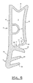
- the strand seal according to the invention can be seen in profile in FIG.
- the strand seal has a holding section 1 on the foot side, to which a sealing section 2 is connected on the head side.
- the sealing section 2 has a closed hollow profile 3, which consists of a profile back 4, an approximately parallel contact surface 5, a wall 6 connecting the two parts and a further wall section 7 connecting the two parts. Roughly speaking, this results in an approximately rectangular basic shape for the hollow profile 3.
- the head-side connecting wall 6 is somewhat longer than the foot-side wall section 7, so that there is a slight deviation from the rectangular shape.
- the contact surface 5 is slightly curved inwards.
- the head-side connecting wall 6 lying between the profile back 4 and the contact surface 5 is further inclined in a V-shape.
- the wall section 7 which represents the connection between the contact surface 5 and the profile back 4 on the side of the hollow profile 3 located towards the holding section 1, has a rounding 8. On the inner wall of this rounding three notches 9, 10 and 11 are provided, the meaning of which is explained below.
- the wall section 7 merges towards the profile back 4 into a web 12 which has a substantially greater wall thickness than the rounding 8. In the area in which the wall section opens into the web 12, the wall section 7 has a curvature which is opposite to the curvature of the curve 8.
- the wall section 7 is thus given the shape of an S curve.
- a chamber 13 is arranged, the outer wall of which is the profile back 4.
- the chamber 13 is approximately semicircular in cross section.
- the chamber 13, which is considerably smaller than the interior of the hollow profile 3, is located approximately in the middle of the longitudinal extent of the hollow profile 3. In the transverse direction, the chamber 13 has a dimension which, in the unloaded state, is approximately over two thirds of the width of the hollow profile 3 extends.
- the profile back 4 merges into a web 14 at the foot end, which together with holding lips 15 and 16 represents the holding section 1. Between the holding section 1 and the sealing section 2 there is a cover lip 17 which covers the profile holding groove in the installed state.
- the contact surface 5 continues into an extension lip 21 on the head side. At the foot of the extension lip 21 there is a tear-off notch 22.
- the profile back carries a reinforcing wall 23 which extends from the foot end of the holding section to the head region of the hollow profile 3, but ends at a certain distance from the head end of the profile back.
- the head-side end edge of the profile back is formed by a reinforcing strand 24, which is rectangular in cross section. Between the reinforcing wall 23 and the reinforcing strand 24 there is softer material, ie the material from which the rest of the seal is made.
- the seal is made of a solid elastic material with a Shore A hardness of 65 while it is the material of the reinforcement wall is an elastic solid material with a Shore A hardness greater than 95.
- the strand seal shown in FIG. 1 is intended in particular for the passive leaf of a double-leaf window without set timber and is preferably processed as follows:
- the strand seal is inserted into the retaining groove of the passive leaf of the window, starting, for example, in the middle of the upper horizontal part of the leaf frame.
- the retaining lips 15 and 16 clamp in the groove and the groove is covered by the cover lip 17.
- the seal is inserted into the rebate groove so that the contact surface 5 faces the weather side when the window is closed and bears against the window frame.
- the profile back 2 lies flat against the sash rebate.
- the strand seal is provided with a V-shaped, rectangular miter cut, which is placed in such a way that the tip of the V-shaped cut lies near the head-side connecting wall 6. The seal can then be placed around the corner.
- extension lip 21 is torn off on the hinge side and on the two horizontal parts of the casement, which is facilitated by the tear-off notch 22.
- the extension lip 21 remains on the vertically extending middle part of the passive leaf and serves - as will be explained in more detail below - as a contact surface for a seal attached to the active leaf.
- the seal also largely retains its shape in the area of the miter corners, so that a tight fit on the sash rebate is ensured.
- the guaranteed shape retention of the seal also ensures that the individual sections of the seal lie so close to one another in the mitred corners, even without welding, that passage of air or moisture is practically avoided.
- the same sealing profile can be used for all four sides of the active leaf, which ensures both rapid processing and seamless sealing, especially at the mitred corners.
- the contact surface 5 When the inactive leaf is closed, the contact surface 5 is pressed against the window frame.
- the frame largely covers the contact surface 5 and extends from the head side of the seal up to the curve 8, approximately to the level of the notch 9.
- the contact surface 5 By pressing against the frame, the contact surface 5 is shifted approximately parallel in the direction of the profile back 4, whereby the V-shaped wall 6 collapses in the shape of an accordion and the curve 8 is turned inside out, so that it fits snugly around the edge of the frame as a sealing bead.
- the turning of the rounding 8 inwards is facilitated on the one hand by the provided notches 9, 10 and 11, which act as a predetermined kink, but on the other hand also by the fact that the wall section 7 is formed much thinner than the material wall of the contact surface 5.
- the one mentioned above S-shaped curvature of the wall section 7 supports the everting.
- the inward turning of the curve 8 is further promoted by the fact that the comparatively thin holding section 7 opens approximately halfway into the cover lip 17, which also has a much greater material thickness and thus holds the foot of the section 7 in a defined position.
- the contact surface 5 is large and full, so that even a low closing pressure is sufficient to ensure a secure seal against drafts and water. With a further compression of the hollow profile, the contact surface 5 comes into contact with the chamber 13, so that the spring force of the overall seal increases suddenly and a complete compression of the seal is prevented.
- the chamber 13 is also sufficiently soft to avoid a hard opening of the wing.
- Figure 2 shows a perspective view of two sections of the seal shown in Figure 1, which are folded into a mitred corner.
- the section running vertically in FIG. 2 carries the extension lip 21, while this is removed from the section running horizontally.
- the vertically extending section is intended for the central web of the passive leaf of a double-leaf window, while the section drawn horizontally in FIG. 2 is intended, for example, for the horizontally running upper part of the leaf frame.
- Figure 3 shows a further embodiment of a strand seal according to the invention.
- the strand seal according to FIG. 3 is particularly suitable as a sash rebate seal. In contrast to the seal shown in FIG. 1, however, it has no extension lip (cf. extension lip 21 in FIG. 1).
- the back of the profile has two sections which are slightly angled at an intermediate point 35.
- the intermediate point 25 is located at the head-side end of the holding section 1.
- the cover lip 17 is longer than in the exemplary embodiment in FIG. 1. Since, due to the lack of the extension lip, the strand seal shown in FIG. 3 is not intended for the passive leaf, but preferably for one leaf Usual wing rebate is used, the profile back lies on all sections of the Always seal the entire surface of the sash rebate.
- FIG. 4 shows a cross section of the middle part of a double-leaf window.
- the vertically running part of the frame of the passive leaf is designated 41, the corresponding part of the active leaf bears the reference number 42.
- the two frames can be opened inwards in the direction of the arrows. In the illustration in FIG. 4, the active leaf is opened a small gap.
- the active leaf 42 is designed in the usual way, as are the window leaves of single-leaf windows.
- the sash frame has a sash groove 43 into which a seal 44 is inserted. This is designed in accordance with the seal in FIG. 3. As can be seen, the holding section of the seal is pressed into the sash groove and the groove is covered by the cover lip. The back of the profile is in full contact with the sash rebate. The contact surface faces the weather side and seals the closed wing on three sides against the window frame (not shown) and on the side shown in FIG. 4 against the passive wing 41.
- a sash groove 45 is also provided in the sash 41 of the passive leaf. This is equipped with a seal 46 according to Figure 1. The holding portion of the seal 46 is in turn forced into the sash groove 45. The cover lip is shortened compared to the seal 44, so that it lies flush against the groove wall. The contact surface is permanently in the middle section of the window shown here on the casement 41. The extension lip 21 extends into the vicinity of the outer edge and serves as a base for the contact surface of the seal 44.
- FIG. 5 shows a strand seal according to the invention, as is particularly suitable for sealing house doors.
- the strand seal has a holding section 1, to which a sealing section 2 connects.
- the sealing section 2 has a closed hollow profile 3, which consists of a profile back 4, an approximately parallel contact surface 5, a wall 6 connecting the two parts and a further wall section 7 connecting the two parts. Roughly speaking, this results in an approximately rectangular basic shape for the hollow profile 3.
- the contact surface 5 is slightly curved inwards.
- the outer connecting wall 6 lying between the profile back 4 and the contact surface 5 is inclined in a V-shape.
- the wall section 7 which represents the connection between the contact surface 5 and the profile back 4 on the side of the hollow profile 3 located towards the holding section 1, has a rounding 8. On the inner wall of this rounding three notches 9, 10 and 11 are provided, the meaning of which is explained in more detail below.
- the wall section 7 merges towards the profile back 2 into a web 12 which has a substantially greater wall thickness than the rounding 8.
- the wall section 7 has a curvature opposite to the rounding 8 and thus runs approximately parallel to the longitudinal direction of the profile body into the web 12. The wall section 7 is thus curved in an S-shape.
- a closed pressure chamber 13 is provided, the outer wall of which represents the profile back 4.
- the pressure chamber 13 is approximately semicircular in cross section.
- the pressure chamber 13, which is significantly smaller than the interior of the hollow profile 3, is located approximately in the middle of the longitudinal extent of the hollow profile 3. In the transverse direction, the pressure chamber 13 has a dimension that in the unloaded state is approximately over two thirds of the width of the hollow profile 3 extends.
- the profile back 4 merges on one side into a web 14 which, together with retaining lips 15 and 16, represents the retaining section 1. Between the holding section 1 and the sealing section 2 there is a cover lip 17 which covers the profile holding groove in the installed state.
- the strand seal is processed as follows:
- Sealing sections cut to size on a front door are provided with a miter cut at their ends and welded to one another.
- the circumferential sealing profile is inserted with the holding section 1 into a corresponding holding groove of a door leaf, the holding lips 15 and 16 wedging in the holding groove and ensuring a secure fit of the sealing profile.
- the cover lip 17 covers the retaining groove and prevents water from entering it. Since the holding section is somewhat inclined in its longitudinal direction with respect to the sealing section 2, the profile back 4 lies snugly against the door rebate, the sealing section 2 being oriented in the direction predetermined by the holding section 1 with elastic deformation.
- the contact surface 5 When the front door is closed, the contact surface 5 is pressed against the door frame or against the threshold.
- the door frame or the threshold extends over the entire contact surface 5 from the head side of the seal to the rounded portion 8, approximately to the level of the notch 9.
- the contact surface 5 becomes approximately parallel in the direction moved to the back of the profile 4, the V-shaped wall 6 collapsing into an accordion shape and the curve 8 being turned inside out so that it fits snugly around the edge of the frame or the threshold as a sealing bead.
- the contact surface 5 is large and full, so that even a low closing pressure is sufficient to ensure a secure seal against drafts and water. With a further compression of the hollow profile, the contact surface 5 comes into contact with the pressure chamber 13, so that the spring force of the overall seal increases suddenly and complete compression of the Seal is prevented. On the other hand, the pressure chamber 13 is also sufficiently soft to avoid a hard opening of the door leaf.
- FIG. 6 shows the seal according to the invention installed in a house door leaf 18, of which only the lower edge is drawn in FIG. 6.
- the door leaf 18 has a groove 19 into which the holding section 1 of the seal with the holding lips 15 and 16 is forced.
- the profile back 4 lies snugly against the door rebate.
- the contact surface 5 opposite the profile back 4 is pressed against a threshold 20, so that the curve 8 of the hollow profile is turned inside out and is placed in the form of a sealing bead around the upper edge of the threshold 20 and thus the penetration of water into the sealing gap between the Threshold 20 and the strand seal is avoided. Due to the sealing bead 8, no water can accumulate in the sealing gap between the door sill 20 and the strand seal, which water could get into the interior of the house when the door was opened.
- the contact surface 5 on the profile back 4 is moved so far that it strikes the pressure chamber 13. In this way, a precise position of the door leaf 18 is defined, since the compression chamber 13 counteracts further compression of the hollow profile 3.
- the cover lip 17 closes the groove 19 tightly. This is not of great importance at the lower sealing section of the door leaf 18 shown in FIG. 6, since no water can penetrate into the upwardly pointing groove 19 anyway.
- the tight closure of the groove 19 by the cover lip 17 is particularly important on the vertical sealing portions (not shown) of the door leaf and on the upper horizontal seal (not shown) of the door leaf, since otherwise water and dirt in the side or behind groove 19 pointing down could penetrate.
- FIG. 7 shows a further exemplary embodiment of a string seal according to the invention. 7 largely corresponds to that of FIG. 3. The description of FIG. 3 is used to avoid repetition.
- the strand seal according to FIG. 7 is additionally provided with a central section 70.
- the middle section 70 the lies between the hollow profile on the head side and the holding section on the foot side, consists of a closed hollow profile 71.
- the wall of the central hollow profile 71 facing away from the profile back 4 is set back relative to the contact surface 5.
- the contact surface 5 merges into a curve 8, which in turn is provided with notches 9 and 10 on its inside.
- the curve 8 does not open into the cover lip 17 of the profile, but rather into a central web 72 which closes off the hollow profile 71 in the central section on the head side.
- the strand seal according to FIG. 7 is particularly suitable for large rebate heights. Despite the large distance between the holding area 1 and the head-side end of the sealing section 2, the strand seal has sufficient stability to be processed in the same way as the strand seal according to FIG. 1.
- FIG. 7 Another embodiment of a strand seal according to the invention can be seen in FIG. This differs from the exemplary embodiment in FIG. 7 by a shortened and reinforced cover lip 17 '.
Abstract
Description
Die Erfindung bezieht sich auf eine elastische Strangdichtung aus Vollmaterial für Türen, Fenster oder dgl. mit einem fußseitigen Halteabschnitt zur Verankerung der Strangdichtung in einer Haltenut, mit einem an dem Halteabschnitt anschließenden Dichtabschnitt, der ein geschlossenes Hohlprofil aufweist, und mit einem sich näherungsweise gerade von dem Dichtabschnitt bis zu dem Halteabschnitt erstreckenden Profilrücken.The invention relates to an elastic strand seal made of solid material for doors, windows or the like. With a foot-side holding section for anchoring the strand seal in a holding groove, with a sealing section adjoining the holding section, which has a closed hollow profile, and with an approximately straight line the sealing section up to the holding section extending profile back.
Dichtungen dieser Art werden häufig zum Abdichten eines Türblatts gegen den Rahmen oder zum Abdichten eines Fensterflügels gegen den Fensterblendrahmen verwendet. Bei bekannten Dichtungen dieser Art werden in der Regel vier Strangabschnitte entsprechend der Länge der für sie jeweils vorgesehenen Aufnahmenut abgelängt, wobei die Enden unter einem Gehrungswinkel von 45° geschnitten werden. Die Stränge werden danach zu einem geschlossenen vierseitigen Rahmen zusammengeschweißt, der dann in die Aufnahmenuten eingesetzt wird. Diese Art der Montage gewährleistet zwar eine exakte und dichte Ausführung der Gehrungsecken, sie ist jedoch zeitaufwendig und teuer und erfordert ein aufwendiges Schweißgerät.Seals of this type are often used to seal a door leaf against the frame or to seal a window sash against the window frame. In known seals of this type, four strand sections are generally cut to length in accordance with the length of the receiving groove provided for them, the ends being cut at a miter angle of 45 °. The strands are then welded together to form a closed four-sided frame, which is then inserted into the receiving grooves. Although this type of assembly ensures an exact and tight design of the mitred corners, it is time-consuming and expensive and requires a complex welding device.
Der Erfindung liegt die Aufgabe zugrunde eine Strangdichtung der eingangs genannten Art zu schaffen, die bequem und zeitsparend montierbar ist und dennoch eine exakte Ausführung der Gehrungsecken ermöglichtThe invention has for its object to provide a strand seal of the type mentioned, which is easy and time-saving to assemble and still allows an exact execution of the miter corners
Diese Aufgabe ist dadurch gelöst, daß bei einer Dichtung der eingangs genannten Art der Profilrücken eine Verstärkungswand aus einem Material aufweist, das wesentlich härter als die übrige Strangdichtung ist. Die Ausbildung des Profilrückens gemäß der Erfindung ermöglicht eine gegenüber dem Stand der Technik wesentlich erleichterte Montage. Es hat sich nämlich gezeigt, daß es ausreicht, die Strangdichtung mit einem V-förmigen Gehrungsausschnitt zu versehen, der so geführt wird, daß die Strangdichtung nicht vollständig durchtrennt wird, vielmehr die Spitze des V-förmigen Endes in einem geringen Abstand zum Seitenrand des Profils liegt. Wenn die Abschnitte zu beiden Seiten des Gehrungsschnitts zusammengelegt werden, um eine Rahmenecke zu bilden, sorgt die Verstärkungswand im Profilrücken dafür, daß keine Verformung auftritt und die Schnittkanten präzise gegeneinander gepreßt werden, so daß sich selbst ohne Verschweißung der Schnittkanten eine präzise und weitgehend dichte Verbindung der Schnittkanten und somit der beiden Strangabschnitte einstellt.This object is achieved in that, in the case of a seal of the type mentioned at the beginning, the profile back has a reinforcing wall made of a material, which is much harder than the rest of the string seal. The design of the profile back according to the invention enables assembly that is considerably easier than in the prior art. It has been shown that it is sufficient to provide the strand seal with a V-shaped miter cut, which is guided so that the strand seal is not completely cut, rather the tip of the V-shaped end at a short distance from the side edge of the profile lies. When the sections on both sides of the miter cut are folded together to form a frame corner, the reinforcement wall in the profile back ensures that no deformation occurs and the cut edges are pressed precisely against each other, so that even without welding the cut edges a precise and largely tight connection the cut edges and thus the two strand sections.
Nach einer vorteilhaften Weiterbildung der Erfindung ist vorgesehen, daß die Verstärkungswand mindestens einen Teil der Außenwand des Profilrückens darstellt.According to an advantageous development of the invention, it is provided that the reinforcement wall represents at least part of the outer wall of the profile back.
Nach einer weiteren vorteilhaften Ausführungsform der Erfindung ist vorgesehen, daß die Verstärkungswand in einem Abstand zum kopfseitigen Ende des Profilrückens endet, und daß am kopfseitigen Ende des Profilrückens ein Verstärkungsstrang angeordnet ist, der aus einem Material besteht, das wesentlich härter als die übrige Strangdichtung ist, während bei Strangdichtungen nach dem Stand der Technik am kopfseitigen Ende einer Rahmenecke der Profilrücken sich häufig aufwirft und somit nicht mehr flach am Flügelfalz anliegt. Es hat sich gezeigt, daß bei der genannten Ausführungsform beim Umlegen der Rahmecken der Profilrücken im Kopfbereich weitgehend eben bleibt und somit dort seine Dichtfunktion sicher erfüllen kann.According to a further advantageous embodiment of the invention, it is provided that the reinforcement wall ends at a distance from the head-side end of the profile back, and that a reinforcement strand is arranged at the head-side end of the profile back, which consists of a material that is much harder than the rest of the strand seal, whereas in the case of strand seals according to the state of the art, the profile back often poses at the head end of a frame corner and thus no longer lies flat against the sash rebate. It has been shown that in the above-mentioned embodiment, when the frame corners are turned over, the profile back remains largely flat in the head region and can therefore reliably fulfill its sealing function there.
Dies gilt insbesondere dann, wenn nach einer weiteren Ausführungsform zwischen dem Verstärkungsstrang und der Verstärkungswand des Profilrückens sich Material befindet, das weicher ist als das Material des Verstärkungsstranges und der Verstärkungswand. Durch die Aufeinanderfolge von hartem, weichem und erneut hartem Material am kopfseitigen Ende des Profilrückens ist sichergestellt, daß dieser sich weitgehend flach um eine Gehrungsecke legen läßt.This applies in particular if, according to a further embodiment, there is material between the reinforcement strand and the reinforcement wall of the profile back that is softer than the material of the reinforcement strand and the reinforcement wall. The succession of hard, soft and again hard material at the head end of the profile back ensures that this can be placed largely flat around a miter corner.
Vorteilhafterweise erstreckt sich die Verstärkungswand bis zum fußseitigen Ende des Halteabschnitts und verleiht somit dem gesamten Profil eine ausreichende Steifigkeit, die ein ausreichend präzises gegenseitiges Anlegen der Schnittkanten in den Gehrungsecken gewährleistet.Advantageously, the reinforcement wall extends to the foot-side end of the holding section and thus gives the entire profile sufficient rigidity, which ensures a sufficiently precise mutual application of the cut edges in the miter corners.
Vorzugsweise weist das härtere Material eine Shore-A-Härte größer als 95 und das weichere Material eine Shore-A-Härte von 55 bis 7O auf.The harder material preferably has a Shore A hardness greater than 95 and the softer material has a Shore A hardness of 55 to 70.
Bekannte Dichtungen weisen des weiteren den Nachteil auf, daß sie entweder einen sehr hohen Schließdruck erfordern oder aber die Dichtwirkung nicht vollständig zufriedenstellend ist. Wird die Dichtung "zu hart" ausgeführt, erfordert sie einen hohen Schließdruck. Wird sie jedoch "zu weich" ausgeführt, kann es vorkommen, daß bei einem unvorsichtigen Schließen der Tür oder auch bei Windbelastung das Hohlprofil vollkommen zusammengequetscht wird, so daß es zu einem harten Aufschlagen des Türblatts auf dem Türrahmen kommt. Nach einer erfinderischen Weiterbildung der Strangdichtung ist vorgesehen, daß innerhalb des geschlossenen Hohlprofils eine im Querschnitt geschlossene Kammer angeordnet ist. Durch diese Kammer wird bei möglichst geringem Schließdruck eine maximale Dichtfunktion gewährleistet. Gleichwohl wird eine vollkommene Komprimierung der Dichtung und ein entsprechend harter Anschlag nach Möglichkeit vermieden.Known seals also have the disadvantage that they either require a very high closing pressure or the sealing effect is not completely satisfactory. If the seal is made "too hard", it requires a high closing pressure. However, if it is carried out "too soft", it can happen that when the door is closed carelessly or when the wind is loaded, the hollow profile is completely squeezed together, so that the door leaf hits the door frame hard. According to an inventive development of the strand seal, it is provided that a closed cross-section chamber is arranged within the closed hollow profile. This chamber ensures a maximum sealing function with the lowest possible closing pressure. Nevertheless, a complete compression of the seal and a correspondingly hard stop is avoided if possible.
Beim Schließen eines Bauteils, beispielsweise einer Tür, wird durch Anlegen des Türblatts an dem Rahmen zunächst das Hohlprofil komprimiert, das sich satt im Zwischenraum zwischen den beiden gegeneinander beweglichen Teilen anlegt. Wenn die beiden gegeneinander abzudichtenden Teile unter weiterer Komprimierung des Hohlprofils über einen gewissen Sollwert hinaus aufeinander zubewegt werden, wird die Kammer komprimiert. Die Kammer muß dabei deformiert werden. Da die Kammer kleiner als das Hohlprofil ist, sind hierzu wesentlich größere Kräfte erforderlich, so daß bei einer unmäßig hohen Kompression der Dichtung die Federkraft rascher zunimmt als bei einer nur leichten Kompression und somit die Schließbewegung abgeblockt wird, ohne daß die Teile hart aufeinandertreffen.When a component, for example a door, is closed, the hollow profile is first compressed by applying the door leaf to the frame, which then fits snugly in the space between the two mutually movable parts. If the two parts to be sealed against one another are moved towards one another with further compression of the hollow profile, the chamber is compressed. The chamber must be deformed. Since the chamber is smaller than the hollow profile, much greater forces are required for this, so that with an unusually high compression of the seal, the spring force increases more rapidly than with only a slight compression, and thus the closing movement is blocked without the parts hitting each other hard.
Nach einer vorteilhaften Ausgestaltung der Erfindung ist die Kammer wesentlich kleiner als das Hohlprofil. Hierdurch wird erreicht, daß erst im letzten Wegstück der Schließbewegung die Kammer in Funktion tritt, dann aber ein sehr rasches Ansteigen der Rückfederkraft bewirkt.According to an advantageous embodiment of the invention, the chamber is significantly smaller than the hollow profile. This ensures that the chamber only comes into operation in the last section of the closing movement, but then causes a very rapid increase in the spring-back force.
Vorzugsweise ist die Kammer etwa halbkreisförmig ausgebildet und stellt somit einen Schlauch dar. Diese Form gewährleistet hohe Rückstellkräfte bei einer übermäßig weitgehenden Schließbewegung und fixiert somit sicher das Türblatt oder den Fensterflügel in einer präzise definierten Position, so daß ein Klappern des Türblatts oder Fensterflügels infolge Windeinwirkung sicher vermieden ist.Preferably, the chamber is approximately semicircular and thus represents a hose. This shape ensures high restoring forces in the event of an excessively extensive closing movement and thus securely fixes the door leaf or the window sash in a precisely defined position, so that the door leaf or window sash rattles as a result of wind is avoided.
Eine etwa rechteckige Ausbildung des Hohlprofils gewährleistet, daß die Anlagefläche und der zu dieser etwa parallel verlaufende Profilrücken satt und großflächig an den gegeneinander abzudichtenden Teilen anliegen und das Eindringen von Wind oder Wasser unterbinden.An approximately rectangular design of the hollow profile ensures that the contact surface and the profile back running approximately parallel to it lie snugly and extensively against the parts to be sealed against one another and prevent the ingress of wind or water.
Vorzugsweise wird dabei die Anlagefläche so geformt, daß sie im unbelasteten Zustand leicht nach innen gewölbt ist. Beim Schließen der Tür oder des Fensters legt sich dann die Anlagefläche an dem Rahmen flach an.Preferably, the contact surface is shaped so that it is slightly curved inwards in the unloaded state. When the door or window is closed, the contact surface lies flat on the frame.
Eine besonders günstige Federwirkung der Kammer ergibt sich, wenn diese etwa in der Mitte der Anlagefläche oder des Profilrückens angeordnet ist und die Kammer in Richtung der Verbindungslinie zwischen der Anlagefläche und dem Profilrücken eine Abmessung aufweist, die etwa die Hälfte bis etwa zwei Drittel des Abstandes zwischen dem Profilrücken und der Anlagefläche beträgt. Dies bewirkt, daß das Hohlprofil etwa bis zu einem Drittel oder etwa bis zur Hälfte seiner Abmessung komprimiert werden kann, ohne daß die Kammer eine entsprechende Komprimierung erfährt. Erst wenn durch eine zu heftige Schließbewegung oder durch Windkraft eine unangemessen große Schließkraft auftritt, wird die Druckkammer zusätzlich deformiert, um die Rückfederkraft rasch ansteigen zu lassen und ein hartes Aufschlagen der Teile zu vermeiden.A particularly favorable spring effect of the chamber results if it is arranged approximately in the middle of the contact surface or the profile back and the chamber has a dimension in the direction of the connecting line between the contact surface and the profile back, which is approximately half to approximately two thirds of the distance between the back of the profile and the contact surface. This has the effect that the hollow profile can be compressed by up to a third or approximately up to half of its dimension without the chamber being appropriately compressed. Only when an inappropriately large closing force occurs due to a too violent closing movement or due to wind power is the pressure chamber additionally deformed in order to allow the spring-back force to increase rapidly and to prevent the parts from hitting hard.
In herstellungstechnischer Hinsicht hat sich eine Ausführungsform als besonders vorteilhaft erwiesen, bei der die Kammer eine Außenwand mit dem Hohlprofil gemeinsam hat.In terms of production technology, an embodiment has proven to be particularly advantageous in which the chamber has an outer wall in common with the hollow profile.
Nach einer weiteren vorteilhaften Ausgestaltung der Erfindung ist vorgesehen, daß das Hohlprofil eine die Auflagefläche mit dem Profilrücken verbindende Wand aufweist, die V-förmig verläuft. Durch diese V-förmige Verbindungswand wird erreicht, daß die Anlagefläche gewissermaßen parallel auf den Profilrücken zubewegt werden kann, wobei sich die V-förmige Fläche, die vorzugsweise mit ihrer Spitze in das Innere des Hohlprofils gerichtet ist, gewissermaßen ziehharmonikaförmig zusammenlegt. Vorzugsweise befindet sich die V-förmige Wand an der dem Halteabschnitt des Profils abgewandten Seite.According to a further advantageous embodiment of the invention, it is provided that the hollow profile has a wall which connects the support surface to the profile back and which runs in a V-shape. This V-shaped connecting wall ensures that the contact surface can be moved to a certain extent parallel to the profile back, the V-shaped surface, which is preferably directed with its tip into the interior of the hollow profile, collapses in a somewhat accordion-like manner. The V-shaped wall is preferably located on the side facing away from the holding section of the profile.
Das Hohlprofil weist nach einer weiteren Ausführungsform einen die Anlagefläche mit dem Profilrücken verbindenden Wandabschnitt auf, der im Übergang zu der Anlagefläche eine nach außen gerichtete Rundung aufweist, wobei die Innenwand der Rundung mindestens eine als Sollknickstelle wirkende Wandeinkerbung aufweist. Der die Rundung aufweisende Wandabschnitt ist dazu bestimmt, die Endkante des an der Anlagefläche anschlagenden Teils aufzunehmen, also beispielsweise die Endkante einer Bodenschwelle, wenn die Dichtung beispielsweise als Haustürdichtung verwendet wird, oder die Endkante eines Tür- oder Fensterblendrahmens. Bei Komprimierung der Strangdichtung wird daher die im unbelasteten Zustand nach außen gewölbte Rundung nach innen geknickt, so daß sich der genannte Wandabschnitt um die Kante des Rahmens oder die Bodenschwelle wulstförmig umlegt und dort eine Abtropfkante bildet, die das Eindringen von Wasser in den Dichtspalt vorzüglich verhindert. Die Wandeinerkerbung erleichtert dabei das Umstülpen der Rundung in den Innenraum des Hohlprofils hinein.According to a further embodiment, the hollow profile has a wall section connecting the contact surface to the profile back, which has an outward curve in the transition to the contact surface, the inner wall of the curve having at least one wall notch acting as a predetermined kink. The wall section having the curvature is intended to accommodate the end edge of the part striking the contact surface, for example the end edge of a threshold if the seal is used, for example, as a door seal, or the end edge of a door or window frame. When the strand seal is compressed, the rounding which is curved outwards in the unloaded state is bent inwards, so that the wall section mentioned bulges around the edge of the frame or the threshold and forms a drip edge there, which prevents water from penetrating into the sealing gap . The wall notch makes it easier to turn the curve into the interior of the hollow profile.
Vorzugsweise ist der Wandabschnitt zum Profilrücken hin wesentlich stärker ausgebildet als im Übergangsbereich zur Anlagefläche. Bei dieser Ausführungsform wird sichergestellt, daß der Wandabschnitt in dem stärker ausgebildeten Teil, also zum Profilrücken hin seine Form auch bei Komprimierung der Strangdichtung beibehält und somit vermieden wird, daß ein unkontrolliertes Zusammenpressen des Wandabschnitts eintritt. Vielmehr wird bei dieser Bauform lediglich die Rundung nach innen umgestülpt und bildet so den gewünschten Dichtwulst über der Kante der Bodenschwelle oder des Rahmens.Preferably, the wall section towards the back of the profile is substantially stronger than in the transition area to the contact surface. In this embodiment, it is ensured that the wall section in the more strongly developed part, that is to say towards the profile back, maintains its shape even when the strand seal is compressed and thus prevents an uncontrolled one Compressing the wall section occurs. Rather, with this design, the rounding is simply turned inside out and thus forms the desired sealing bead over the edge of the threshold or the frame.
Nach einer weiteren vorteilhaften Ausgestaltung der Erfindung ist vorgesehen, daß sich an den die Rundung aufweisenden Wandabschnitt der Halteabschnitt anschließt, und daß sich der Wandabschnitt in eine die Haltenut im Einbauzustand bedeckende Abdecklippe und in die genannte Rundung gabelt. Bei dieser Bauweise ist die Umstülpung der Rundung nach innen besonders sicher gewährleistet, da die die Haltenut bedeckende Abdecklippe zusammen mit dem zum Profilrücken hin gelegenen Teil des Wandabschnitts für die Formstabilität der Dichtung in diesem Bereich auch in eingespanntem Zustand sorgt, während der Rundungsbereich mit den als Sollknickstellen wirkenden Wandeinkerbungen sich bei eingespannter Dichtung zwangsläufig in der gewünschten Weise nach innen stülpt, um die genannte Abtropfkante zu bilden.According to a further advantageous embodiment of the invention, it is provided that the holding section adjoins the wall section having the curvature, and that the wall section bifurcates into a cover lip covering the holding groove in the installed state and into the aforementioned curvature. With this construction, the inside-out of the rounding is ensured particularly securely, since the cover lip covering the retaining groove together with the part of the wall section lying towards the back of the profile ensures the shape stability of the seal in this area even in the clamped state, while the rounding area with the as When the gasket is clamped in, the wall notches that act on the predetermined kinks inevitably turn inside in the desired manner in order to form the drip edge mentioned.
Nach einer weiteren vorteilhaften Ausführungsform ist vorgesehen, daß der Halteabschnitt einen Steg aufweist, der aus einer Verlängerung des Profilrückens besteht, und daß an dem Steg zwei Haltelippen angeordnet sind, mit denen sich der Halteabschnitt in der Nut verriegelt.According to a further advantageous embodiment it is provided that the holding section has a web, which consists of an extension of the profile back, and that two holding lips are arranged on the web, with which the holding section is locked in the groove.
Nach einer besonders erfinderischen Weiterbildung der Strangdichtung ist vorgesehen, daß am kopfseitigen Ende der Anlagefläche des Dichtabschnitts eine Verlängerungslippe ausgebildet ist. Eine solche Strangdichtung eignet sich vorzüglich für zweiflügelige Fenster ohne Setzholz. Die Dichtung gemäß der Erfindung kann bei einem solchen Fenster in die Haltenut des Flügelfalzes des Standflügelfalzes eingelegt werden und dichtet den Standflügel an drei Seiten, nämlich an der Bandseite sowie den beiden horizontalen Flügelrahmenteilen gegen den Blendrahmen des Fensters. Dabei weist der Profilrücken gegen den Flügel und die Anlagefläche des Hohlprofils liegt im geschlossenen Zustand des Standflügels an den entsprechenden Teilen des Blendrahmens an. An der vierten Seite des Standflügelrahmens, d.h. an der der Bandseite gegenüberliegenden Seite, die im geschlossenen Zustand gegen den Gangflügel abgedichtet werden muß, liegt die Strangdichtung mit der Anlagefläche des Hohlprofils am Standflügel auf. Ebenso legt sich die Verlängerungslippe an den Standflügel an und bildet dort eine Unterlage für die Anlagefläche einer im Gangflügel angeordneten entsprechenden Dichtung. Auf diese Weise kann erreicht werden, daß der Standflügel eines zweiflügeligen Holzfensters ohne Setzholz mit einer einheitlichen Dichtung bestückt werden kann, obwohl bei einem solchen Standflügel die Abdichtung an drei Seiten in Richtung zum Fensterblendrahmen, also nach außen und an der vierten Seite in Richtung zum Flügelfalz des Gangflügels, also nach innen, stattfinden muß.According to a particularly inventive development of the strand seal, it is provided that an extension lip is formed at the head end of the contact surface of the sealing section. Such a strand seal is particularly suitable for double-leaf windows without set timber. In such a window, the seal according to the invention can be inserted into the retaining groove of the sash rebate of the fixed sash rebate and seals the fixed sash on three sides, namely on the hinge side and the two horizontal sash frame parts against the window frame. The back of the profile points against the sash and the contact surface of the hollow profile rests on the corresponding parts of the frame when the inactive leaf is closed. On the fourth side of the inactive leaf frame, ie on the side opposite the hinge side, which must be sealed against the active leaf in the closed state, the strand seal lies with the contact surface of the hollow profile on the inactive leaf. As well puts the extension lip on the inactive leaf and forms a base for the contact surface of a corresponding seal arranged in the active leaf. In this way it can be achieved that the passive leaf of a double-leaf wooden window can be fitted with a uniform seal without setting timber, although with such a passive leaf the seal on three sides towards the window frame, i.e. outwards and on the fourth side towards the sash rebate of the active wing, i.e. inside.
Nach einer vorteilhaften Ausführungsform der Erfindung ist vorgesehen, daß die Verlängerungslippe eine Abreißkerbe aufweist. Mittels dieser Abreißkerbe kann die Verlängerungslippe leicht in den Bereichen abgetrennt werden, in denen sie nicht benötigt wird. Das sind im oben geschilderten Fall die Bandseite und die beiden horizontalen Teile des Flügelrahmens.According to an advantageous embodiment of the invention, it is provided that the extension lip has a tear-off notch. Using this tear-off notch, the extension lip can be easily separated in areas where it is not needed. In the case described above, these are the hinge side and the two horizontal parts of the casement.
Nach einer weiteren vorteilhaften Ausführungsform der Erfindung ist vorgesehen, daß zwischen dem kopfseitigen Dichtabschnitt und dem fußseitigen Halteabschnitt mindestens ein weiteres Hohlprofil angeordnet ist. Eine auf diese Weise ausgebildete Strangdichtung ist besonders für größere Falzhöhen geeignet. Vorteilhaft ist dabei, wenn die dem Profilrücken gegenüberliegende Wand des weiteren Hohlprofils gegenüber der Anlagefläche des kopfseitigen Hohlprofils zurückgesetzt ist, insbesondere wenn das weitere Hohlprofil fußseitig durch die die Haltenut bedeckende Abdecklippe begrenzt wird. Eine auf diese Weise ausgebildete Strangdichtung ist für große Falzhöhen geeignet und kann gleichwohl um die Ecken umgelegt werden, ohne daß durch die Eckenumlegung eine störende Verformung des Profils auftritt.According to a further advantageous embodiment of the invention, it is provided that at least one further hollow profile is arranged between the head-side sealing section and the foot-side holding section. A strand seal designed in this way is particularly suitable for larger rebate heights. It is advantageous if the wall of the further hollow profile opposite the profile back is set back relative to the contact surface of the head-side hollow profile, in particular if the further hollow profile is delimited on the foot side by the cover lip covering the holding groove. A strand seal designed in this way is suitable for large rebate heights and can nevertheless be folded around the corners without the profile being disturbed by the corner folding.
Die Erfindung wird nachfolgend anhand der in den Figuren schematisch dargestellten Ausführungsbeispiele näher erläutert. Es zeigen:
- FIGUR 1:
- eine Strangdichtung (vergrößert), im Querschnitt;
- FIGUR 2:
- eine perspektivische Ansicht einer Strangdichtung gemäß Figur 1 mit Gehrungsecke;
- FIGUR 3:
- eine weitere Ausführungsform einer Strangdichtung gemäß der Erfindung.
- FIGUR 4:
- einen Querschnitt durch den Mittelteil eines zweiflügeligen Fensters mit eingesetzten Strangdichtungen gemäß
den Figuren 1 und 3; - FIGUR 5:
- eine Strangdichtung gemäß einer weiteren Ausführungsform der Erfindung;
- FIGUR 6:
- die Unterkante einer Haustür mit einer erfindungsgemäßen Strangdichtung;
- FIGUR 7:
- ein weiteres Ausführungsbeispiel einer Strangdichtung gemäß der Erfindung;
- FIGUR 8:
- ein weiteres Ausführungsbeispiel der Strangdichtung gemäß der Erfindung;
- FIGURE 1:
- a strand seal (enlarged), in cross section;
- FIGURE 2:
- a perspective view of a strand seal according to Figure 1 with mitred corner;
- FIGURE 3:
- a further embodiment of a strand seal according to the invention.
- FIGURE 4:
- a cross-section through the central part of a two-leaf window with inserted sealing elements according to Figures 1 and 3;
- FIGURE 5:
- a strand seal according to a further embodiment of the invention;
- FIGURE 6:
- the lower edge of a front door with an extrusion seal according to the invention;
- FIGURE 7:
- a further embodiment of a string seal according to the invention;
- FIGURE 8:
- another embodiment of the strand seal according to the invention;
Gleiche oder ähnliche Teile werden in den Zeichnungen mit den gleichen Bezugszeichen bezeichnet.Identical or similar parts are designated with the same reference symbols in the drawings.
In Figur 1 ist die erfindungsgemäße Strangdichtung im Profil zu erkennen. Die Strangdichtung weist fußseitig einen Halteabschnitt 1 auf, an den sich kopfseitig ein Dichtabschnitt 2 anschließt. Der Dichtabschnitt 2 weist ein geschlossenes Hohlprofil 3 auf, das aus einem Profilrücken 4, einer dazu etwa parallel verlaufenden Anlagefläche 5, einer die beiden Teile verbindenden Wand 6 und einem weiteren die beiden Teile verbindenden Wandabschnitt 7 besteht. Für das Hohlprofil 3 ergibt sich somit grob gesehen eine etwa rechteckige Grundform. Allerdings ist die kopfseitige Verbindungswand 6 etwas länger als der fußseitige Wandabschnitt 7, so daß eine leichte Abweichung von der Rechteckform vorhanden ist. Des weiteren ist die Anlagefläche 5 leicht nach innen gewölbt.The strand seal according to the invention can be seen in profile in FIG. The strand seal has a
Die zwischen dem Profilrücken 4 und der Anlagefläche 5 liegende kopfseitige Verbindungswand 6 ist des weiteren V-förmig nach innen geneigt.The head-
Der Wandabschnitt 7, der die Verbindung zwischen der Anlagefläche 5 und dem Profilrücken 4 an der zum Halteabschnitt 1 gelegenen Seite des Hohlprofils 3 darstellt, weist eine Rundung 8 auf. An der Innenwand dieser Rundung sind drei Einkerbungen 9, 10 und 11 vorgesehen, deren Bedeutung weiter unten erläutert wird. Der Wandabschnitt 7 geht zum Profilrücken 4 hin in einen Steg 12 über, der eine wesentlich größere Wandstärke als die Rundung 8 aufweist. In dem Bereich, in dem der Wandabschnitt in den Steg 12 mündet, weist der Wandabschnitt 7 eine Krümmung auf, die der Krümmung der Rundung 8 entgegen gerichtet ist. Der Wandabschnitt 7 erhält somit die Form einer S-Kurve.The
Im Innern des Hohlprofils 3 ist eine Kammer 13 angeordnet, deren äußere Wand der Profilrücken 4 ist. Die Kammer 13 ist im Querschnitt etwa halbkreisförmig. Die Kammer 13, die wesentlich kleiner als der Innenraum des Hohlprofils 3 ist, befindet sich etwa in der Mitte der Längserstreckung des Hohlprofils 3. In Querrichtung weist die Kammer 13 eine Abmessung auf, die sich im unbelasteten Zustand etwa über zwei Drittel der Breite des Hohlprofils 3 erstreckt. Der Profilrücken 4 geht am fußseitigen Ende in einen Steg 14 über, der zusammen mit Haltelippen 15 und 16 den Halteabschnitt 1 darstellt. Zwischen dem Halteabschnitt 1 und dem Dichtabschnitt 2 befindet sich eine Abdecklippe 17, die im Einbauzustand die Profilhaltenut überdeckt.In the interior of the
Die Anlagefläche 5 setzt sich kopfseitig fort in eine Verlängerungslippe 21. Am Fuß der Verlängerungslippe 21 befindet sich eine Abrißeinkerbung 22.The
Der Profilrücken trägt eine Verstärkungswand 23, die vom fußseitigen Ende des Halteabschnitts bis in den kopfseitigen Bereich des Hohlprofils 3 reicht, jedoch in einem gewissen Abstand zum kopfseitigen Ende des Profilrückens endet. Die kopfseitige Endkante des Profilrückens wird durch einen Verstärkungsstrang 24 gebildet, der im Querschnitt rechteckig ist. Zwischen der Verstärkungswand 23 und dem Verstärkungsstrang 24 befindet sich weicheres Material, d.h. das Material, aus dem die übrige Dichtung gefertigt ist. Die Dichtung ist aus einem elastischen Vollmaterial mit einer Shore-A-Härte von 65 gefertigt, während es sich bei dem Material der Verstärkungwand um ein elastisches Vollmaterial der Shore-A-Härte größer als 95 handelt.The profile back carries a reinforcing
Die in Figur 1 gezeigte Strangdichtung ist insbesondere für den Standflügel eines zweiflügeligen Fensters ohne Setzholz bestimmt und wird vorzugsweise wie folgt verarbeitet:The strand seal shown in FIG. 1 is intended in particular for the passive leaf of a double-leaf window without set timber and is preferably processed as follows:
Die Strangdichtung wird in die Haltenut des Standflügels des Fensters, beginnend beispielsweise in der Mitte des oberen Horizontalteiles des Flügelrahmens, eingefügt. Dabei verspannen sich die Haltelippen 15 und 16 in der Falznut und die Falznut wird durch die Abdecklippe 17 abgedeckt. Die Dichtung wird so in die Falznut eingesetzt, daß die Anlagefläche 5 bei geschlossenem Fenster zur Wetterseite weist und an dem Blendrahmen des Fensters anliegt. Der Profilrücken 2 liegt flach an dem Flügelfalz an. Sobald eine Ecke des Flügelrahmens erreicht ist, wird die Strangdichtung mit einem V-förmigen, rechteckigen Gehrungsschnitt versehen, der so gelegt wird, daß die Spitze des V-förmigen Schnitts in der Nähe der kopfseitigen Verbindungswand 6 liegt. Sodann kann die Dichtung um die Ecke gelegt werden. Nachdem dies an allen vier Ecken des Flügelrahmens geschehen ist, wird das Ende entsprechend abgelängt, so daß sich insgesamt ein rechteckiger Dichtungsrahmen ergibt. An der Bandseite und an den beiden horizontalen Teilen des Flügelrahmens wird die Verlängerungslippe 21 abgerissen, was durch die Abreißkerbe 22 erleichtert wird. An dem vertikal verlaufenden Mittelteil des Standflügels bleibt die Verlängerungslippe 21 jedoch bestehen und dient - wie weiter unten näher erläutert wird - als Auflagfläche für eine am Gangflügel angebrachte Dichtung.The strand seal is inserted into the retaining groove of the passive leaf of the window, starting, for example, in the middle of the upper horizontal part of the leaf frame. The retaining
Infolge der durch die Verstärkungswand 23 und auch durch den Verstärkungsstrang 24 erreichten Verstärkung der Dichtung im Bereich des Profilrückens behält die Dichtung auch im Bereich der Gehrungsecken weitgehend ihre Form, so daß ein sattes Anliegen am Flügelfalz gewährleistet ist. Durch die gewährleistete Formhaltigkeit der Dichtung ist auch gesichert, daß in den Gehrungsecken die einzelnen Abschnitte der Dichtung selbst ohne Verschweißung so dicht aneinander liegen, daß ein Durchtritt von Luft oder Feuchtigkeit praktisch vermieden ist.As a result of the reinforcement of the seal in the area of the profile back achieved by the
Wie oben erläutert, kann für alle vier Seiten des Gangflügels das gleiche Dichtungsprofil verwendet werden, wodurch sowohl eine zügige Verarbeitung als auch eine lückenlose Abdichtung vor allem an den Gehrungsecken gewährleistet ist.As explained above, the same sealing profile can be used for all four sides of the active leaf, which ensures both rapid processing and seamless sealing, especially at the mitred corners.
Bei geschlossenem Standflügel wird die Anlagefläche 5 gegen den Blendrahmen des Fensters gedrückt. Der Blendrahmen überdeckt weitgehend die Anlagefläche 5 und erstreckt sich von der Kopfseite der Dichtung her bis zur Rundung 8, etwa bis in Höhe der Einkerbung 9. Durch das Andrücken gegen den Blendrahmen wird die Anlagefläche 5 etwa parallel in Richtung auf den Profilrücken 4 verschoben, wobei sich die V-förmige Wand 6 ziehharmonikaförmig zusammenlegt und sich die Rundung 8 nach innen umstülpt, so daß sie sich als Dichtwulst satt um die Kante des Blendrahmens legt. Das Umstülpen der Rundung 8 nach innen wird einerseits durch die vorgesehenen Einkerbungen 9, 10 und 11 erleichtert, die als Sollknickstelle wirken, andererseits jedoch auch dadurch, daß der Wandabschnitt 7 wesentlich dünner ausgebildet ist, als die Materialwand der Anlagefläche 5. Auch die oben erwähnte S-förmige Krümmung des Wandabschnitts 7 unterstützt das Umstülpen. Das Nachinnenstülpen der Rundung 8 wird des weiteren dadurch gefördert, daß der vergleichsweise dünne Halteabschnitt 7 etwa in halber Höhe in die Abdecklippe 17 mündet, die ebenfalls eine weitaus größere Materialstärke aufweist und somit den Fuß des Abschnitts 7 an definierter Stelle festhält.When the inactive leaf is closed, the
Die Anlagefläche 5 liegt großflächig und satt an, so daß bereits ein geringer Schließdruck genügt, um eine sichere Abdichtung gegen Luftzug und Wasser zu gewährleisten. Bei einer weiteren Komprimierung des Hohlprofils kommt die Anlagefläche 5 in Anlage an die Kammer 13, so daß sich die Federkraft der Gesamtdichtung sprunghaft erhöht und eine vollständige Komprimierung der Dichtung verhindert wird. Andererseits ist auch die Kammer 13 noch ausreichend weich, um ein hartes Aufschlagen des Flügels zu vermeiden.The
Auf diese Weise ist auch eine präzise Positionierung des Fensterflügels möglich, da einer weiteren Komprimierung des Hohlprofils die Kammer 13 entgegenwirkt. Dadurch wird sicher vermieden, daß das Fenster bei Windbelastung klappert.In this way, a precise positioning of the window sash is also possible, since the
Figur 2 zeigt in perspektivischer Ansicht zwei Abschnitte der in Figur 1 dargestellten Dichtung, die zu einer Gehrungsecke zusammengelegt sind.Figure 2 shows a perspective view of two sections of the seal shown in Figure 1, which are folded into a mitred corner.
Der in Figur 2 vertikal verlaufende Abschnitt trägt die Verlängerungslippe 21, während diese bei dem horizontal verlaufenden Abschnitt entfernt ist. Der vertikal verlaufende Abschnitt ist - wie oben erläutert - für den Mittelsteg des Standflügels eines zweiflügeligen Fensters bestimmt, während der in Figur 2 horizontal gezeichnete Abschnitt beispielsweise für den horizontal verlaufenden oberen Teil des Flügelrahmens vorgesehen ist. Obwohl von beiden Dichtabschnitten völlig unterschiedliche Dichtfunktionen erfüllt werden, ist ersichtlich, daß es sich abgesehen von der Verlängerungslippe um eine einheitlich ausgebildete Dichtung handelt, die eine lückenlose Abdichtung ermöglicht.The section running vertically in FIG. 2 carries the
Figur 3 zeigt ein weiteres Ausführungsbeispiel einer Strangdichtung gemäß der Erfindung.Figure 3 shows a further embodiment of a strand seal according to the invention.
Da die Dichtung gemäß Figur 3 weitgehend wie die in Figur 1 beschriebene Dichtung aufgebaut ist, wird zur Vermeidung von Wiederholungen nachfolgend nur auf die Gesichtspunkte eingegangen, in denen sich die in Figur 3 gezeigte Dichtung von der in Figur 1 gezeigten Dichtung unterscheidet.Since the seal according to FIG. 3 is largely constructed like the seal described in FIG. 1, in order to avoid repetitions, only the points of view in which the seal shown in FIG. 3 differs from the seal shown in FIG. 1 are discussed below.
Die Strangdichtung gemäß Figur 3 ist insbesondere als Flügelfalzdichtung geeignet. Sie weist jedoch im Gegensatz zu der in Figur 1 gezeigten Dichtung keine Verlängerungslippe auf (vgl. Verlängerungslippe 21 in Figur 1). Der Profilrücken weist zwei Abschnitte auf, die an einem Zwischenpunkt 35 leicht gegeneinander abgewinkelt sind. Der Zwischenpunkt 25 liegt am kopfseitigen Ende des Halteabschnitts 1. Die Abdecklippe 17 ist länger ausgeführt als beim Ausführungsbeispiel der Figur 1. Da infolge des Fehlens der Verlängerungslippe die in Figur 3 dargestellte Strangdichtung nicht für den Standflügel eine zweiflügeligen Fensters bestimmt ist, sondern vorzugsweise bei einem üblichen Flügelfalz eingesetzt wird, liegt der Profilrücken auf allen Abschnitten der Dichtung stets vollflächig am Flügelfalz an. Durch die oben erwähnte abgewinkelte Ausbildung des Profilrückens wird ein Anpreßdruck im Bereich des Profilkopfes erreicht, wenn die Dichtung in ihre Haltenut eingequetscht ist. Da die in Figur 3 dargestellte Dichtung - wie erwähnt - für übliche Fensterflügel und nicht für den Standflügel eines zweiflügeligen Fensters bestimmt ist, kann die Abdecklippe 17 länger ausgeführt sein, so daß durch die Abdecklippe 17 die Flügelfalznut vollständig überdeckt wird.The strand seal according to FIG. 3 is particularly suitable as a sash rebate seal. In contrast to the seal shown in FIG. 1, however, it has no extension lip (cf.
Figur 4 zeigt einen Querschnitt der Mittelpartie eines zweiflügeligen Fensters. Der senkrecht verlaufende Teil des Rahmens des Standflügels ist mit 41 bezeichnet, der entsprechende Teil des Gangflügels trägt das Bezugszeichen 42. Die beiden Rahmen können nach innen in Richtung der Pfeile geöffnet werden. In der Darstellung der Figur 4 ist der Gangflügel einen kleinen Spalt geöffnet.FIG. 4 shows a cross section of the middle part of a double-leaf window. The vertically running part of the frame of the passive leaf is designated 41, the corresponding part of the active leaf bears the
Der Gangflügel 42 ist in der üblichen Weise ausgebildet, wie auch Fensterflügel von einflügeligen Fenstern ausgebildet sind. Der Flügelrahmen weist eine Flügelfalznut 43 auf, in die eine Dichtung 44 eingefügt ist. Diese ist entsprechend der Dichtung in Figur 3 ausgebildet Wie ersichtlich ist der Halteabschnitt der Dichtung in die Flügelfalznut eingepreßt und die Nut wird durch die Abdecklippe überdeckt. Der Profilrücken liegt vollflächig an der Flügelfalznut an. Die Anlagefläche weist zur Wetterseite und dichtet den geschlossenen Flügel an drei Seiten gegen den Blendrahmen des Fensters (nicht dargestellt) und an der in Figur 4 gezeigten Seite gegen den Standflügel 41 ab.The
In dem Flügelrahmen 41 des Standflügels ist ebenfalls eine Flügelfalznut 45 vorgesehen. Diese ist mit einer Dichtung 46 gemäß Figur 1 bestückt. Der Halteabschnitt der Dichtung 46 ist wiederum in die Flügelfalznut 45 eingezwängt. Die Abdecklippe ist - im Vergleich zur Dichtung 44 - verkürzt ausgebildet, so daß sie stumpf an der Nutwand anliegt. Die Anlagefläche liegt in dem hier dargestellten Mittelabschnitt des Fensters dauerhaft an dem Flügelrahmen 41 an. Die Verlängerungslippe 21 erstreckt sich bis in die Nähe der äußeren Kante und dient als Unterlage für die Anlagefläche der Dichtung 44.A
In den hier nicht gezeigten Teilen des Flügelrahmens 41 ist die Verlängerungslippe 21 der Dichtung 46 entfernt und die Dichtung 46 weist mit ihrer Anlagefläche gegen den Blendrahmen des Fensters, zu dem sie bei geschlossenem Fenster einen dichten Abschluß herstellt.In the parts of the
Das Ausführungsbeispiel der Figur 5 zeigt eine erfindungsgemäße Strangdichtung, wie sie insbesondere für die Abdichtung von Haustüren geeignet ist. Die Strangdichtung weist einen Halteabschnitt 1 auf, an den sich ein Dichtabschnitt 2 anschließt. Der Dichtabschnitt 2 weist ein geschlossenes Hohlprofil 3 auf, das aus einem Profilrücken 4, einer dazu etwa parallel verlaufenden Anlagefläche 5, einer die beiden Teile verbindenden Wand 6 und einem weiteren die beiden Teile verbindenden Wandabschnitt 7 besteht. Für das Hohlprofil 3 ergibt sich somit grob gesehen eine etwa rechteckige Grundform. Allerdings ist die Anlagefläche 5 leicht nach innen gewölbt.The exemplary embodiment in FIG. 5 shows a strand seal according to the invention, as is particularly suitable for sealing house doors. The strand seal has a
Die zwischen Profilrücken 4 und Anlagefläche 5 liegende äußere Verbindungswand 6 ist V-förmig nach innen geneigt.The outer connecting
Der Wandabschnitt 7, der die Verbindung zwischen der Anlagefläche 5 und dem Profilrücken 4 an der zum Halteabschnitt 1 gelegenen Seite des Hohlprofils 3 darstellt, weist eine Rundung 8 auf. An der Innenwand dieser Rundung sind drei Einkerbungen 9, 10 und 11 vorgesehen, deren Bedeutung weiter unten näher erläutert wird. Der Wandabschnitt 7 geht zum Profilrücken 2 hin in einen Steg 12 über, der eine wesentlich größere Wandstärke als die Rundung 8 aufweist. Der Wandabschnitt 7 weist eine zur Rundung 8 entgegengesetzte Krümmung auf und läuft somit etwa parallel zur Längsrichtung des Profilkörpers in den Steg 12 ein. Der Wandabschnitt 7 ist somit S-förmig gekrümmt.The
Im Innern des Hohlprofils 3 ist eine geschlossene Druckkammer 13 vorgesehen, deren äußere Wand den Profilrücken 4 darstellt. Die Druckkammer 13 ist im Querschnitt etwa halbkreisförmig. Die Druckkammer 13, die wesentlich kleiner als der Innenraum des Hohlprofils 3 ist, befindet sich etwa in der Mitte der Längserstreckung des Hohlprofils 3. In Querrichtung weist die Druckkammer 13 eine Abmessung auf, die sich im unbelasteten Zustand etwa über zwei Drittel der Breite des Hohlprofils 3 erstreckt.In the interior of the
Der Profilrücken 4 geht an einer Seite in einen Steg 14 über, der zusammen mit Haltelippen 15 und 16 den Halteabschnitt 1 darstellt. Zwischen dem Halteabschnitt 1 und dem Dichtabschnitt 2 befindet sich eine Abdecklippe 17, die im Einbauzustand die Profilhaltenut überdeckt.The profile back 4 merges on one side into a
Auf das Maß einer Haustür abgelängte Dichtabschnitte werden an ihren Enden mit einem Gehrungsschnitt versehen und miteinander verschweißt. Das umlaufende Dichtungsprofil wird mit dem Halteabschnitt 1 in eine entsprechende Haltenut eines Türblatts eingesteckt, wobei sich die Haltelippen 15 und 16 in der Haltenut verkeilen und einen sicheren Sitz des Dichtungsprofils gewährleisten. Die Abdecklippe 17 deckt die Haltenut ab und verhindert das Eindringen von Wasser in diese. Da der Halteabschnitt gegenüber dem Dichtabschnitt 2 in seiner Längsrichtung etwas geneigt ist, legt sich der Profilrücken 4 an dem Türfalz satt an, wobei unter elastischer Verformung der Dichtabschnitt 2 in der durch den Halteabschnitt 1 vorgegebenen Richtung ausgerichtet wird.Sealing sections cut to size on a front door are provided with a miter cut at their ends and welded to one another. The circumferential sealing profile is inserted with the holding
Beim Schließen der Haustür wird die Anlagefläche 5 gegen den Türrahmen oder gegen die Bodenschwelle gedrückt. Der Türrahmen bzw. die Bodenschwelle erstreckt sich über die ganze Anlagefläche 5 von der Kopfseite der Dichtung her bis zur Rundung 8, etwa bis in Höhe der Einkerbung 9. Durch das Andrücken gegen den Türrahmen bzw. die Bodenschwelle wird die Anlagefläche 5 etwa parallel in Richtung auf den Profilrücken 4 verschoben, wobei sich die V-förmige Wand 6 ziehharmonikaförmig zusammenlegt und sich die Rundung 8 nach innen umstülpt, so daß sie sich als Dichtwulst satt um die Kante des Rahmens bzw. der Bodenschwelle legt.When the front door is closed, the
Die Anlagefläche 5 liegt großflächig und satt an, so daß bereits ein geringer Schließdruck genügt, um eine sichere Abdichtung gegen Luftzug und Wasser zu gewährleisten. Bei einer weiteren Komprimierung des Hohlprofils kommt die Anlagefläche 5 in Anlage an die Druckkammer 13, so daß sich die Federkraft der Gesamtdichtung sprunghaft erhöht und eine vollständige Komprimierung der Dichtung verhindert wird. Andererseits ist auch die Druckkammer 13 noch ausreichend weich, um ein hartes Aufschlagen des Türblatts zu vermeiden.The
Figur 6 zeigt die erfindungsgemäße Dichtung eingebaut in einem Haustürblatt 18, von dem in Figur 6 nur der untere Rand gezeichnet ist. Das Türblatt 18 weist eine Nut 19 auf, in die der Halteabschnitt 1 der Dichtung mit den Haltelippen 15 und 16 eingezwängt ist. Der Profilrücken 4 liegt satt an dem Türfalz an. Die dem Profilrücken 4 gegenüberliegende Anlagefläche 5 ist gegen eine Bodenschwelle 20 gedrückt, so daß die Rundung 8 des Hohlprofils nach innen umgestülpt ist und sich in Form eines Dichtwulstes um die obere Kante der Bodenschwelle 20 legt und somit das Eindringen von Wasser in den Dichtspalt zwischen der Bodenschwelle 20 und der Strangdichtung vermieden wird. Durch den Dichtwulst 8 kann sich in dem Dichtspalt zwischen der Türschwelle 20 und der Strangdichtung kein Wasser ansammeln, das beim Öffnen der Tür in das Hausinnere gelangen könnte.FIG. 6 shows the seal according to the invention installed in a
Wie ersichtlich ist die Anlagefläche 5 auf den Profilrücken 4 soweit verschoben, daß sie an der Druckkammer 13 anschlägt. Auf diese Weise ist eine präzise Position des Türblatts 18 definiert, da einer weiteren Komprimierung des Hohlprofils 3 die Druckkammer 13 entgegenwirkt. Die Abdecklippe 17 schließt die Nut 19 dicht ab. Dies ist an dem in Figur 6 gezeigten unteren Dichtabschnitt des Türblatts 18 nicht von großer Bedeutung, da dort in die nach oben weisende Nut 19 ohnehin kein Wasser eindringen kann. Der dichte Abschluß der Nut 19 durch die Abdecklippe 17 ist jedoch an den senkrecht verlaufenden Dichtungsabschnitten (nicht gezeigt) des Türblatts sowie an der oberen horizontalen Dichtung (nicht gezeigt) des Türblatts besonders wichtig, da dort sonst Wasser und Schmutz in die seitlich bzw. nach unten weisende Nut 19 eindringen könnten.As can be seen, the
In Figur 7 ist ein weiteres Ausführungsbeispiel einer Strangdichtung nach der Erfindung dargestellt. Die Strangdichtung der Figur 7 entspricht weitgehend derjenigen der Figur 3. Auf die Beschreibung zu Figur 3 wird zur Vermeidung von Wiederholungen Bezug genommen. Die Strangdichtung gemäß Figur 7 ist zusätzlich mit einem Mittelabschnitt 70 versehen. Der Mittelabschnitt 70, der zwischen dem kopfseitigen Hohlprofil und dem fußseitigen Halteabschnitt liegt, besteht aus einem geschlossenen Hohlprofil 71. Die dem Profilrücken 4 abgewandte Wandung des mittleren Hohlprofils 71 ist gegenüber der Anlagefläche 5 zurückgesetzt. Ähnlich wie beim Ausführungsbeispiel der Figur 3 geht die Anlagefläche 5 in eine Rundung 8 über, die wiederum an ihrer Innenseite mit Kerben 9 und 10 versehen ist. Die Rundung 8 mündet jedoch nicht in die Abdecklippe 17 des Profils, sondern in einen Mittelsteg 72, der das Hohlprofil 71 im Mittelabschnitt kopfseitig abschließt.FIG. 7 shows a further exemplary embodiment of a string seal according to the invention. 7 largely corresponds to that of FIG. 3. The description of FIG. 3 is used to avoid repetition. The strand seal according to FIG. 7 is additionally provided with a
Die Strangdichtung gemäß Figur 7 ist insbesondere für große Falzhöhen geeignet. Trotz des großen Abstandes zwischen dem Haltebereich 1 und dem kopfseitigen Ende des Dichtabschnitts 2 weist die Strangdichtung eine ausreichende Stabilität aus, um in der gleichen Weise wie etwa die Strangdichtung gemäß Figur 1 verarbeitet werden zu können.The strand seal according to FIG. 7 is particularly suitable for large rebate heights. Despite the large distance between the holding
Eine weitere Ausführungsform einer Strangdichtung gemäß der Erfindung ist in Figur 8 zu erkennen. Diese unterscheidet sich von dem Ausführungsbeispiel der Figur 7 durch eine verkürzte und verstärkte Abdecklippe 17'.Another embodiment of a strand seal according to the invention can be seen in FIG. This differs from the exemplary embodiment in FIG. 7 by a shortened and reinforced cover lip 17 '.
Claims (25)
Priority Applications (1)
| Application Number | Priority Date | Filing Date | Title |
|---|---|---|---|
| AT90122190T ATE96498T1 (en) | 1990-01-11 | 1990-11-20 | ELASTIC STRIP SEAL MADE OF SOLID MATERIAL FOR WINDOWS, DOORS OR THE LIKE. |
Applications Claiming Priority (2)
| Application Number | Priority Date | Filing Date | Title |
|---|---|---|---|
| DE9000263U DE9000263U1 (en) | 1990-01-11 | 1990-01-11 | |
| DE9000263U | 1990-01-11 |
Publications (2)
| Publication Number | Publication Date |
|---|---|
| EP0436810A1 true EP0436810A1 (en) | 1991-07-17 |
| EP0436810B1 EP0436810B1 (en) | 1993-10-27 |
Family
ID=6849946
Family Applications (1)
| Application Number | Title | Priority Date | Filing Date |
|---|---|---|---|
| EP90122190A Expired - Lifetime EP0436810B1 (en) | 1990-01-11 | 1990-11-20 | Solid sealing strips for windows, doors or the like |
Country Status (4)
| Country | Link |
|---|---|
| EP (1) | EP0436810B1 (en) |
| AT (1) | ATE96498T1 (en) |
| DE (2) | DE9000263U1 (en) |
| DK (1) | DK0436810T3 (en) |
Cited By (8)
| Publication number | Priority date | Publication date | Assignee | Title |
|---|---|---|---|---|
| DE4200624C1 (en) * | 1992-01-13 | 1993-06-24 | Deventer Profile Gmbh & Co Kg, 1000 Berlin, De | Elastic cord seal for doors and windows etc. - comprises back connected to head section which in turn is attached to strip section and projects into cross fillet and when sealed, chamber wall is located on back |
| EP0603874A1 (en) * | 1992-12-23 | 1994-06-29 | BRÜGMANN FRISOPLAST GmbH | Sealing profile for doors |
| EP0728900A2 (en) * | 1995-02-23 | 1996-08-28 | DEVENTER PROFILE GmbH & Co. KG | Elastic sealing strip for windows, doors and the like |
| DE19719474A1 (en) * | 1997-05-07 | 1998-10-08 | Bruegmann Frisoplast Gmbh | Track-shaped spread seal for window |
| EP0890701A1 (en) * | 1997-07-11 | 1999-01-13 | Orfeo Bertelli | Gasket for door or window structure |
| EP0892143A1 (en) * | 1997-07-17 | 1999-01-20 | SCHÜCO International KG | Sealing for windows, doors and facades |
| EP0953722A1 (en) * | 1998-05-02 | 1999-11-03 | CEFO-Elastic-Profil-Gmbh | Profiled sealing strip for windows, doors and the like |
| AT406287B (en) * | 1994-01-28 | 2000-03-27 | Dipro Dichtungssysteme Gmbh | STRING-SHAPED SINGLE-FOLDING GASKET FOR WINDOWS, DOORS OR THE LIKE |
Families Citing this family (2)
| Publication number | Priority date | Publication date | Assignee | Title |
|---|---|---|---|---|
| DE29822668U1 (en) * | 1998-12-19 | 2000-05-18 | Niemann Hans Dieter | Magnetic seal of a window or door |
| DE202010004368U1 (en) * | 2010-03-30 | 2011-08-11 | Semperit Ag Holding | Strand-shaped stop seal profile |
Citations (5)
| Publication number | Priority date | Publication date | Assignee | Title |
|---|---|---|---|---|
| US3448543A (en) * | 1968-02-20 | 1969-06-10 | Stanley Works | Weatherstrip for door sill and door assembly employing same |
| EP0021989A2 (en) * | 1979-06-19 | 1981-01-07 | Hutchinson-Mapa | Sealing strips for moving surfaces |
| DE8525275U1 (en) * | 1985-09-04 | 1985-10-17 | Deventer Profile GmbH & Co KG, 1000 Berlin | Profile strip seal made of elastic material for windows, doors or the like. |
| DE8711518U1 (en) * | 1987-08-25 | 1987-10-15 | Deventer Profile Gmbh & Co Kg, 1000 Berlin, De | |
| EP0258152A1 (en) * | 1986-08-28 | 1988-03-02 | Bernard Bon | Device for sealing a double casement window or door window against air and water, and windows or door windows provided with such a device |
-
1990
- 1990-01-11 DE DE9000263U patent/DE9000263U1/de not_active Expired - Lifetime
- 1990-11-20 EP EP90122190A patent/EP0436810B1/en not_active Expired - Lifetime
- 1990-11-20 AT AT90122190T patent/ATE96498T1/en not_active IP Right Cessation
- 1990-11-20 DK DK90122190.3T patent/DK0436810T3/en active
- 1990-11-20 DE DE90122190T patent/DE59003248D1/en not_active Expired - Fee Related
Patent Citations (5)
| Publication number | Priority date | Publication date | Assignee | Title |
|---|---|---|---|---|
| US3448543A (en) * | 1968-02-20 | 1969-06-10 | Stanley Works | Weatherstrip for door sill and door assembly employing same |
| EP0021989A2 (en) * | 1979-06-19 | 1981-01-07 | Hutchinson-Mapa | Sealing strips for moving surfaces |
| DE8525275U1 (en) * | 1985-09-04 | 1985-10-17 | Deventer Profile GmbH & Co KG, 1000 Berlin | Profile strip seal made of elastic material for windows, doors or the like. |
| EP0258152A1 (en) * | 1986-08-28 | 1988-03-02 | Bernard Bon | Device for sealing a double casement window or door window against air and water, and windows or door windows provided with such a device |
| DE8711518U1 (en) * | 1987-08-25 | 1987-10-15 | Deventer Profile Gmbh & Co Kg, 1000 Berlin, De |
Cited By (10)
| Publication number | Priority date | Publication date | Assignee | Title |
|---|---|---|---|---|
| DE4200624C1 (en) * | 1992-01-13 | 1993-06-24 | Deventer Profile Gmbh & Co Kg, 1000 Berlin, De | Elastic cord seal for doors and windows etc. - comprises back connected to head section which in turn is attached to strip section and projects into cross fillet and when sealed, chamber wall is located on back |
| EP0603874A1 (en) * | 1992-12-23 | 1994-06-29 | BRÜGMANN FRISOPLAST GmbH | Sealing profile for doors |
| AT406287B (en) * | 1994-01-28 | 2000-03-27 | Dipro Dichtungssysteme Gmbh | STRING-SHAPED SINGLE-FOLDING GASKET FOR WINDOWS, DOORS OR THE LIKE |
| EP0728900A2 (en) * | 1995-02-23 | 1996-08-28 | DEVENTER PROFILE GmbH & Co. KG | Elastic sealing strip for windows, doors and the like |
| EP0728900A3 (en) * | 1995-02-23 | 1997-10-15 | Deventer Profile | Elastic sealing strip for windows, doors and the like |
| DE19719474A1 (en) * | 1997-05-07 | 1998-10-08 | Bruegmann Frisoplast Gmbh | Track-shaped spread seal for window |
| EP0890701A1 (en) * | 1997-07-11 | 1999-01-13 | Orfeo Bertelli | Gasket for door or window structure |
| EP0892143A1 (en) * | 1997-07-17 | 1999-01-20 | SCHÜCO International KG | Sealing for windows, doors and facades |
| EP0953722A1 (en) * | 1998-05-02 | 1999-11-03 | CEFO-Elastic-Profil-Gmbh | Profiled sealing strip for windows, doors and the like |
| US6679005B1 (en) | 1998-05-02 | 2004-01-20 | Ronald Cebulla | Sealing profile including reinforcing sliding hard layers |
Also Published As
| Publication number | Publication date |
|---|---|
| EP0436810B1 (en) | 1993-10-27 |
| DE9000263U1 (en) | 1990-03-01 |
| DK0436810T3 (en) | 1994-02-21 |
| ATE96498T1 (en) | 1993-11-15 |
| DE59003248D1 (en) | 1993-12-02 |
Similar Documents
| Publication | Publication Date | Title |
|---|---|---|
| EP0436810B1 (en) | Solid sealing strips for windows, doors or the like | |
| EP0786576B1 (en) | Elastic sealing strip for windows, doors or the like | |
| DE4402604C1 (en) | Window or door sealing strip | |
| DE102008023500A1 (en) | Door e.g. outer door, for use in building, has additional floor seal arranged on side of leaf pointing horizontal to floor and/or floor barrier, pointed downwards to side provided in inner area and viewed in installation direction | |
| EP1881147B1 (en) | Sealing between a panel and a frame profil | |
| DE102008046753A1 (en) | Elastic sealing strip for e.g. window, has head area including profile backs, and sealing and connection bars and bar sections, which are made of foam material i.e. thermoplastic elastomer | |
| DE102005044420B3 (en) | Flexible strand seal e.g. for window, door, has closed hollow cross section having head section and which has back and foot section having seal provided in retaining groove of window | |
| DE19847955A1 (en) | Sealing profile for window or door | |
| CH676376A5 (en) | Strip-type door-leaf seal | |
| CH667128A5 (en) | STRING-SHAPED PROFILE GASKET MADE OF ELASTIC MATERIAL FOR WINDOWS OR DOORS. | |
| DE19719474A1 (en) | Track-shaped spread seal for window | |
| EP0877143B1 (en) | Sealing strip | |
| AT400877B (en) | ELASTIC STRING SEAL FOR DOORS, WINDOWS OR THE LIKE | |
| AT390123B (en) | PROFILE STRING GASKET MADE OF ELASTIC MATERIAL FOR WINDOWS, DOORS OR THE LIKE. | |
| DE19750161A1 (en) | Strand-like universal seal for windows and doors | |
| DE102004024127B3 (en) | Elastic thread seal e.g. for windows, doors, has hollow cross section with retaining rib for anchorage in retaining groove of wing crease of window and head and floor areas connected by back | |
| DE10002554A1 (en) | Extruded seal for windows and doors has closed hollow profiled section of first material and on side of contact bearing wall remote from same a second material having a lower coefficient of sliding friction | |
| DE202004007829U1 (en) | Flexible strand seal for e.g. windows, doors, has connecting post connected to end of a back profile such that a sufficient vertex is formed between the transverse bar and the extension bridge of a sealing bar | |
| DE102013204944B4 (en) | Elastic strand seal for windows, doors or the like. | |
| DE10126006A1 (en) | Window attachment as insect screen for insertion in casement frame has elastically deformable spring element supported on casement frame profile and mounted on retaining angle which engages behind casement when installed | |
| DE2013319C3 (en) | Sealing device for pivoting or turning sashes of windows, doors or the like | |
| EP0416246B1 (en) | Sealing strip for window frames and wings | |
| AT409524B (en) | PROFILE SEAL | |
| CH691189A5 (en) | Flexible extruded seal for sealing a glazing in the wing of a window or door. | |
| EP3988757B1 (en) | Strip seal made of elastic foam material |
Legal Events
| Date | Code | Title | Description |
|---|---|---|---|
| PUAI | Public reference made under article 153(3) epc to a published international application that has entered the european phase |
Free format text: ORIGINAL CODE: 0009012 |
|
| AK | Designated contracting states |
Kind code of ref document: A1 Designated state(s): AT BE CH DE DK FR IT LI LU NL |
|
| 17P | Request for examination filed |
Effective date: 19911116 |
|
| 17Q | First examination report despatched |
Effective date: 19920520 |
|
| GRAA | (expected) grant |
Free format text: ORIGINAL CODE: 0009210 |
|
| AK | Designated contracting states |
Kind code of ref document: B1 Designated state(s): AT BE CH DE DK FR IT LI LU NL |
|
| REF | Corresponds to: |
Ref document number: 96498 Country of ref document: AT Date of ref document: 19931115 Kind code of ref document: T |
|
| REF | Corresponds to: |
Ref document number: 59003248 Country of ref document: DE Date of ref document: 19931202 |
|
| ITF | It: translation for a ep patent filed |
Owner name: JACOBACCI CASETTA & PERANI S.P.A. |
|
| ET | Fr: translation filed | ||
| EPTA | Lu: last paid annual fee | ||
| REG | Reference to a national code |
Ref country code: DK Ref legal event code: T3 |
|
| PLBE | No opposition filed within time limit |
Free format text: ORIGINAL CODE: 0009261 |
|
| STAA | Information on the status of an ep patent application or granted ep patent |
Free format text: STATUS: NO OPPOSITION FILED WITHIN TIME LIMIT |
|
| 26N | No opposition filed | ||
| REG | Reference to a national code |
Ref country code: CH Ref legal event code: PUE Owner name: BRUEGMANN FRISOPLAST GMBH TRANSFER- DIPRO DICHTUNG Ref country code: CH Ref legal event code: NV Representative=s name: ISLER & PEDRAZZINI AG |
|
| REG | Reference to a national code |
Ref country code: FR Ref legal event code: TP |
|
| NLS | Nl: assignments of ep-patents |
Owner name: DIPRO DICHTUNGSSYSTEME GMBH |
|
| PGFP | Annual fee paid to national office [announced via postgrant information from national office to epo] |
Ref country code: NL Payment date: 20051117 Year of fee payment: 16 |
|
| PGFP | Annual fee paid to national office [announced via postgrant information from national office to epo] |
Ref country code: FR Payment date: 20051118 Year of fee payment: 16 |
|
| PGFP | Annual fee paid to national office [announced via postgrant information from national office to epo] |
Ref country code: AT Payment date: 20051122 Year of fee payment: 16 |
|
| PGFP | Annual fee paid to national office [announced via postgrant information from national office to epo] |
Ref country code: CH Payment date: 20051123 Year of fee payment: 16 Ref country code: BE Payment date: 20051123 Year of fee payment: 16 |
|
| PGFP | Annual fee paid to national office [announced via postgrant information from national office to epo] |
Ref country code: DK Payment date: 20051124 Year of fee payment: 16 |
|
| PGFP | Annual fee paid to national office [announced via postgrant information from national office to epo] |
Ref country code: LU Payment date: 20051228 Year of fee payment: 16 |
|
| PGFP | Annual fee paid to national office [announced via postgrant information from national office to epo] |
Ref country code: DE Payment date: 20060111 Year of fee payment: 16 |
|
| PG25 | Lapsed in a contracting state [announced via postgrant information from national office to epo] |
Ref country code: AT Free format text: LAPSE BECAUSE OF NON-PAYMENT OF DUE FEES Effective date: 20061120 |
|
| PG25 | Lapsed in a contracting state [announced via postgrant information from national office to epo] |
Ref country code: LI Free format text: LAPSE BECAUSE OF NON-PAYMENT OF DUE FEES Effective date: 20061130 Ref country code: DK Free format text: LAPSE BECAUSE OF NON-PAYMENT OF DUE FEES Effective date: 20061130 Ref country code: CH Free format text: LAPSE BECAUSE OF NON-PAYMENT OF DUE FEES Effective date: 20061130 Ref country code: BE Free format text: LAPSE BECAUSE OF NON-PAYMENT OF DUE FEES Effective date: 20061130 |
|
| PGFP | Annual fee paid to national office [announced via postgrant information from national office to epo] |
Ref country code: IT Payment date: 20061130 Year of fee payment: 17 |
|
| PG25 | Lapsed in a contracting state [announced via postgrant information from national office to epo] |
Ref country code: NL Free format text: LAPSE BECAUSE OF NON-PAYMENT OF DUE FEES Effective date: 20070601 Ref country code: DE Free format text: LAPSE BECAUSE OF NON-PAYMENT OF DUE FEES Effective date: 20070601 |
|
| REG | Reference to a national code |
Ref country code: DK Ref legal event code: EBP |
|
| REG | Reference to a national code |
Ref country code: CH Ref legal event code: PL |
|
| NLV4 | Nl: lapsed or anulled due to non-payment of the annual fee |
Effective date: 20070601 |
|
| REG | Reference to a national code |
Ref country code: FR Ref legal event code: ST Effective date: 20070731 |
|
| BERE | Be: lapsed |
Owner name: *DIPRO DICHTUNGSSYSTEME G.M.B.H. Effective date: 20061130 |
|
| PG25 | Lapsed in a contracting state [announced via postgrant information from national office to epo] |
Ref country code: FR Free format text: LAPSE BECAUSE OF NON-PAYMENT OF DUE FEES Effective date: 20061130 |
|
| PG25 | Lapsed in a contracting state [announced via postgrant information from national office to epo] |
Ref country code: LU Free format text: LAPSE BECAUSE OF NON-PAYMENT OF DUE FEES Effective date: 20061120 |
|
| PG25 | Lapsed in a contracting state [announced via postgrant information from national office to epo] |
Ref country code: IT Free format text: LAPSE BECAUSE OF NON-PAYMENT OF DUE FEES Effective date: 20071120 |