EP0436155A2 - Ausdrückpistole für Doppelwandkartuschen - Google Patents
Ausdrückpistole für Doppelwandkartuschen Download PDFInfo
- Publication number
- EP0436155A2 EP0436155A2 EP90123790A EP90123790A EP0436155A2 EP 0436155 A2 EP0436155 A2 EP 0436155A2 EP 90123790 A EP90123790 A EP 90123790A EP 90123790 A EP90123790 A EP 90123790A EP 0436155 A2 EP0436155 A2 EP 0436155A2
- Authority
- EP
- European Patent Office
- Prior art keywords
- double
- tube
- cylindrical tube
- piston rod
- cylindrical
- Prior art date
- Legal status (The legal status is an assumption and is not a legal conclusion. Google has not performed a legal analysis and makes no representation as to the accuracy of the status listed.)
- Granted
Links
Images
Classifications
-
- B—PERFORMING OPERATIONS; TRANSPORTING
- B05—SPRAYING OR ATOMISING IN GENERAL; APPLYING FLUENT MATERIALS TO SURFACES, IN GENERAL
- B05C—APPARATUS FOR APPLYING FLUENT MATERIALS TO SURFACES, IN GENERAL
- B05C17/00—Hand tools or apparatus using hand held tools, for applying liquids or other fluent materials to, for spreading applied liquids or other fluent materials on, or for partially removing applied liquids or other fluent materials from, surfaces
- B05C17/005—Hand tools or apparatus using hand held tools, for applying liquids or other fluent materials to, for spreading applied liquids or other fluent materials on, or for partially removing applied liquids or other fluent materials from, surfaces for discharging material from a reservoir or container located in or on the hand tool through an outlet orifice by pressure without using surface contacting members like pads or brushes
- B05C17/00553—Hand tools or apparatus using hand held tools, for applying liquids or other fluent materials to, for spreading applied liquids or other fluent materials on, or for partially removing applied liquids or other fluent materials from, surfaces for discharging material from a reservoir or container located in or on the hand tool through an outlet orifice by pressure without using surface contacting members like pads or brushes with means allowing the stock of material to consist of at least two different components
- B05C17/00559—Hand tools or apparatus using hand held tools, for applying liquids or other fluent materials to, for spreading applied liquids or other fluent materials on, or for partially removing applied liquids or other fluent materials from, surfaces for discharging material from a reservoir or container located in or on the hand tool through an outlet orifice by pressure without using surface contacting members like pads or brushes with means allowing the stock of material to consist of at least two different components the different components being stored in coaxial chambers
-
- B—PERFORMING OPERATIONS; TRANSPORTING
- B05—SPRAYING OR ATOMISING IN GENERAL; APPLYING FLUENT MATERIALS TO SURFACES, IN GENERAL
- B05C—APPARATUS FOR APPLYING FLUENT MATERIALS TO SURFACES, IN GENERAL
- B05C17/00—Hand tools or apparatus using hand held tools, for applying liquids or other fluent materials to, for spreading applied liquids or other fluent materials on, or for partially removing applied liquids or other fluent materials from, surfaces
- B05C17/005—Hand tools or apparatus using hand held tools, for applying liquids or other fluent materials to, for spreading applied liquids or other fluent materials on, or for partially removing applied liquids or other fluent materials from, surfaces for discharging material from a reservoir or container located in or on the hand tool through an outlet orifice by pressure without using surface contacting members like pads or brushes
- B05C17/00553—Hand tools or apparatus using hand held tools, for applying liquids or other fluent materials to, for spreading applied liquids or other fluent materials on, or for partially removing applied liquids or other fluent materials from, surfaces for discharging material from a reservoir or container located in or on the hand tool through an outlet orifice by pressure without using surface contacting members like pads or brushes with means allowing the stock of material to consist of at least two different components
-
- B—PERFORMING OPERATIONS; TRANSPORTING
- B05—SPRAYING OR ATOMISING IN GENERAL; APPLYING FLUENT MATERIALS TO SURFACES, IN GENERAL
- B05C—APPARATUS FOR APPLYING FLUENT MATERIALS TO SURFACES, IN GENERAL
- B05C17/00—Hand tools or apparatus using hand held tools, for applying liquids or other fluent materials to, for spreading applied liquids or other fluent materials on, or for partially removing applied liquids or other fluent materials from, surfaces
- B05C17/005—Hand tools or apparatus using hand held tools, for applying liquids or other fluent materials to, for spreading applied liquids or other fluent materials on, or for partially removing applied liquids or other fluent materials from, surfaces for discharging material from a reservoir or container located in or on the hand tool through an outlet orifice by pressure without using surface contacting members like pads or brushes
- B05C17/01—Hand tools or apparatus using hand held tools, for applying liquids or other fluent materials to, for spreading applied liquids or other fluent materials on, or for partially removing applied liquids or other fluent materials from, surfaces for discharging material from a reservoir or container located in or on the hand tool through an outlet orifice by pressure without using surface contacting members like pads or brushes with manually mechanically or electrically actuated piston or the like
Definitions
- the present invention relates to an ejection gun for double-wall cartridges, consisting of a manually operated pistol grip, a trough-shaped half-shell, a piston rod slidably mounted therein, an essentially circular ejection plate arranged at the front end of the piston rod and a one-sided open, releasably and displaceably mounted in the trough-shaped half shell.
- cylindrical tube in which two spaced stamps are attached, according to patent (patent application P 38 35 093).
- Such a squeeze gun with a cylindrical tube open on one side offers the considerable advantage that the latter is pushed continuously from the squeeze plate of the squeeze gun over the double-wall cartridge, the slightly offset piston ends acting on the piston heads of the two chambers.
- the two pistons move in the direction of the ejection opening, with no expansion to the outside at the places of greatest stress on the wall of the double-wall cartridge can, as this is prevented with certainty by the cylindrical tube that surrounds the double wall cartridge.
- the two punches have the shape of a cylinder jacket section and are fastened coaxially to the tube on the tube plate; the double wall cartridge, which is enclosed by this tube, is divided by a partition into two semicircular chambers, in each of which a pasty mass is arranged.
- the two punches are arranged at a distance from one another such that the partition of the double-wall cartridge engages in the gap formed between them.
- the object of the present invention is to design a dispensing gun of the type mentioned in the introduction in such a way that double wall cartridges can be squeezed out uniformly with it, which are not divided into two semicircular chambers by a central dividing wall, but rather into an inner one by means of a tube coaxial with the longitudinal axis cylindrical space and are divided into an outer annular space in which the two pasty masses are arranged separately.
- the punches have the shape of a cylinder section and that they are fastened to the tube sheet coaxially to one another and to the longitudinal axis of the tube.
- the longitudinal extension of the two punches of different diameters is advantageously smaller than the longitudinal extension of the cylindrical tube.
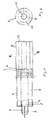
- the double-wall cartridge 1 shows a longitudinal section through a double-wall cartridge 1, which is provided with an outlet opening 2 and a mixing tip 3 which can be screwed thereon.
- the double-wall cartridge 1 is divided by a cylindrical partition 4 into two chambers 5, 6, in each of which a pasty mass is arranged.
- the cylindrical partition 4 separates an inner cylindrical chamber 5 from an outer annular chamber 6 surrounding it.
- the cylindrical chamber 5 is closed by a cylindrical piston 8 and the annular chamber 6 by an annular piston 7.
- the two pistons 7, 8 are slidable towards the outlet opening.
- the two punches 10, 11 are dimensioned such that the inner circular punch 11 acts on the circular piston 8, which closes the inner cylindrical chamber 5, and the second punch 10 arranged coaxially thereto acts on the annular piston 7, which closes the annular chamber 6.
- the cylindrical tube can be made of plastic or metal, such as. As aluminum, exist, wherein it is adapted in its outer diameter to the inner diameter of the trough-shaped half-shell of the firing gun, and its inner diameter is adapted to the outer diameter of the double-wall cartridge 1 to be pressed out.
Abstract
Description
- Die vorliegende Erfindung betrifft eine Ausdrückpistole für Doppelwandkartuschen, bestehend aus einem handbetätigten Pistolengriff, einer wannenförmigen Halbschale, einer darin verschiebbar gelagerten Kolbenstange, einer am vorderen Ende der Kolbenstange angeordneten, im wesentlichen kreisförmigen Ausdrückplatte und einem in der wannenförmigen Halbschale lösbar und verschiebbar gelagerten einseitig offenen, zylindrischen Rohr, in dem zwei im Abstand voneinander angeordnete Stempel befestigt sind, nach Patent (Patentanmeldung P 38 35 093).
- Eine derartige Ausdrückpistole mit einem einseitig offenen zylindrischen Rohr bietet den erheblichen Vorteil, daß letzteres von der Ausdrückplatte der Ausdrückpistole kontinuierlich über die Doppelwandkartusche geschoben wird, wobei die etwas nach rückwärts versetzten Stempelenden die Kolbenböden der beiden Kammern beaufschlagen. Entsprechend dem Vorschub des zylindrischen Rohrs bewegen sich die beiden Kolben in Richtung zur Ausdrücköffnung, wobei an den Stellen der größten Beanspruchung der Wandung der Doppelwandkartusche keine Aufweitung nach außen erfolgen kann, da dies durch das zylindrische Rohr, das die Doppelwandkartusche umschließt, mit Sicherheit verhindert wird.
- Bei dem im Hauptpatent beschriebenen zylindrischen Rohr weisen die beiden Stempel die Form eines Zylindermantelabschnitts auf und sind koaxial zum Rohr am Rohrboden befestigt; die Doppelwandkartusche, die durch dieses Rohr umschlossen wird, ist durch eine Trennwand in zwei halbkreisförmige Kammern unterteilt, in denen jeweils eine pastöse Masse angeordnet ist. Um die beiden halbkreisförmigen Kolben in den beiden halbkreisförmigen Kammern zu beaufschlagen, sind die beiden Stempel im Abstand voneinander derart angeordnet, daß in dem zwischen ihnen gebildeten Spalt die Trennwand der Doppelwandkartusche eingreift.
- Aufgabe der vorliegenden Erfindung ist es, eine Ausdrückpistole der eingangs näher genannten Art dahingehend auszugestalten, daß mit ihr Doppelwandkartuschen gleichmäßig auspreßbar sind, die nicht durch eine mittig verlaufende Trennwand in zwei halbkreisförmige Kammern unterteilt sind, sondern die durch ein zur Längsachse koaxiales Rohr in einen inneren zylindrischen Raum und in einen äußeren ringförmigen Raum unterteilt sind, in denen die beiden pastösen Massen getrennt angeordnet sind.
- Zur Lösung dieser Aufgabe wird vorgeschlagen, daß die Stempel die Form eines Zylinderabschnitts aufweisen und daß sie koaxial zueinander und zur Längsachse des Rohrs am Rohrboden befestigt sind.
- Vorteilhafterweise ist die Längsausdehnung der beiden Stempel unterschiedlichen Durchmessers kleiner als die Längsausdehnung des zylindrischen Rohrs.
- Im folgenden wird die Erfindung anhand der Zeichnung näher erläutert, in der ein vorteilhaftes Ausführungsbeispiel dargestellt ist. Es zeigen
- Fig. 1
- einen Schnitt durch eine Doppelwandkartusche und zugehörigem zylindrischen Rohr und
- Fig. 2
- einen Schnitt durch das zylindrische Rohr und die beiden Stempel entlang der Linie A-A von Fig. 1.
- In Fig. 1 ist ein Längsschnitt durch eine Doppelwandkartusche 1 dargestellt, die mit einer Auslaßöffnung 2 und einer ggfs. darauf aufschraubbaren Mischspitze 3 versehen ist. In Längsrichtung ist die Doppelwandkartusche 1 durch eine zylindrische Trennwand 4 in zwei Kammern 5, 6 unterteilt, in denen jeweils eine pastöse Masse angeordnet ist. Die zylindrische Trennwand 4 trennt dabei eine innere zylindrische Kammer 5 von einer diese umgebende äußeren ringförmigen Kammer 6. Die zylindrische Kammer 5 wird dabei durch einen zylindrischen Kolben 8 verschlossen und die ringförmige Kammer 6 durch einen ringförmigen Kolben 7. Die beiden Kolben 7, 8 sind in Richtung zur Auslaßöffnung hin verschiebbar.
- Zum gleichzeitigen präzisen Ausdrücken der beiden pastösen Massen in den beiden Kammern 5, 6 wird nun in eine nicht dargestellte herkömmliche Ausdrückpistole, die aus einem handbetätigten Pistolengriff besteht, einer wannenförmigen Halbschale, einer darin verschiebbar gelagerte Kolbenstange und einer am vorderen Ende der Kolbenstange angeordneten, im wesentlichen kreisförmigen Ausdrückplatte, ein einseitig offenes zylindrisches Rohr 9 eingelegt, in dem zwei koaxial zueinander und zur Längsachse 12 der Kartusche 1 angeordnete kreisförmige Stempel 10, 11 befestigt sind. Das zylindrische Rohr 9 ist an seinem der Ausdrückplatte der Ausdrückpistole zugeordneten Ende 13 verschlossen, wobei an diesem Boden die beiden zylinderförmigen Stempel 10, 11 befestigt sind (Fig. 2), deren Längsausdehnung geringer ist als diejenige des zylindrische Rohrs 9.
- Die beiden Stempel 10, 11 sind, wie Fig. 2 zeigt, derartig bemessen, daß der innere kreisförmige Stempel 11 den kreisförmigen Kolben 8 beaufschlagt, der die innere zylindrische Kammer 5 verschließt und der zweite koaxial dazu angeordnete Stempel 10 den ringförmigen Kolben 7 beaufschlagt, der die ringförmige Kammer 6 verschließt.
- Das zylindrische Rohr kann aus Kunststoff oder Metall, wie z. B. Aluminium, bestehen, wobei es in seinem Außendurchmesser an den Innendurchmesser der wannenförmigen Halbschale der Ausdrückpistole angepaßt ist, und in seinem Innendurchmesser an den Außendurchmesser der auszudrückenden Doppelwandkartusche 1 angepaßt ist.
- Nach dem Einlegen des zylindrischen Rohrs in die Ausdrückpistole und der Doppelwandkartusche 1 dergestalt, daß die beiden Kolben 7, 8 auf den vorderen Enden der Stempel 10, 11 zur Ruhe kommen, wird bei Betätigung des Pistolengriffes der Ausdrückpistole die nicht dargestellte Ausdrückplatte gegen den Boden 13 des zylindrischen Rohrs 9 gepreßt, wobei bei anhaltendem Kraftaufwand sich das zylindrische Rohr 9 über die Außenwand der Doppelwandkartusche 1 schiebt (Fig. 1), wobei mit einer geringen zeitlichen Verzögerung die beiden Stempel 10, 11 die beiden Kolben 7, 8 beaufschlagen und diese in Richtung zur Auslaßöffnung der Doppelwandkartusche befördern. Aufgrund des Voreilens des vorderen Randes des zylindrischen Rohrs 9 bezüglich der vorderen Enden der beiden Stempel 10, 11 wird ein Aufweiten der Außenwand der Doppelwandkartusche 1 verhindert, da an den Stellen der größten Druckbelastung diese fest vom zylindrischen Rohr umschlossen wird. Jede Art von ungleichmäßigem Ausdrücken, d. h. ungleich großen Mengen, wird bei gleichem Rauminhalt der beiden Kammern 5, 6 vermieden. Bei ungleich großem Fassungsvermögen der beiden Kammern 5, 6 für die pastöse Masse wird ein dadurch vorgegebenes konstantes Mischungsverhältnis exakt eingehalten.
Claims (2)
- Ausdrückpistole für Doppelwandkartuschen, bestehend aus einem handbetätigten Pistolengriff, einer wannenförmigen Halbschale, einer darin verschiebbar gelagerten Kolbenstange, einer am vorderen Ende der Kolbenstange angeordneten, im wesentlichen kreisförmigen Ausdrückplatte und einem in der wannenförmigen Halbschale lösbar und verschiebbar angeordneten, einseitig zylindrischen Rohr, in dem zwei im Abstand voneinander angeordnete Stempel befestigt sind, nach Patent (Patentanmeldung P 38 35 093), dadurch gekennzeichnet, daß die Stempel die Form eines Zylinderabschnittes aufweisen und daß sie koaxial zueinander und zur Längsachse des Rohrs am Rohrboden befestigt sind.
- Ausdrückpistole nach Anspruch 1, dadurch gekennzeichnet, daß die Längsausdehnung der Stempel unterschiedlichen Durchmessers kleiner ist als die Längsausdehnung des zylindrischen Rohrs.
Applications Claiming Priority (2)
| Application Number | Priority Date | Filing Date | Title |
|---|---|---|---|
| DE4000205 | 1990-01-05 | ||
| DE19904000205 DE4000205A1 (de) | 1988-10-14 | 1990-01-05 | Ausdrueckpistole fuer doppelwandkartuschen |
Publications (3)
| Publication Number | Publication Date |
|---|---|
| EP0436155A2 true EP0436155A2 (de) | 1991-07-10 |
| EP0436155A3 EP0436155A3 (en) | 1991-12-04 |
| EP0436155B1 EP0436155B1 (de) | 1994-08-24 |
Family
ID=6397659
Family Applications (1)
| Application Number | Title | Priority Date | Filing Date |
|---|---|---|---|
| EP90123790A Expired - Lifetime EP0436155B1 (de) | 1990-01-05 | 1990-12-11 | Ausdrückpistole für Doppelwandkartuschen |
Country Status (6)
| Country | Link |
|---|---|
| US (1) | US5139171A (de) |
| EP (1) | EP0436155B1 (de) |
| JP (1) | JPH0747317A (de) |
| AT (1) | ATE110305T1 (de) |
| CA (1) | CA2033627A1 (de) |
| DE (1) | DE59006902D1 (de) |
Cited By (6)
| Publication number | Priority date | Publication date | Assignee | Title |
|---|---|---|---|---|
| EP2314383A1 (de) * | 2009-10-22 | 2011-04-27 | P.C. Cox Limited | Kolben für eine Ausdrückpistole für Kartuschen |
| CN102802812A (zh) * | 2009-06-16 | 2012-11-28 | 苏舍米克斯帕克有限公司 | 用于单次使用的多组分存储筒 |
| US8528793B2 (en) | 2010-12-23 | 2013-09-10 | P. C. Cox Limited | Actuator |
| US8607824B2 (en) | 2010-12-23 | 2013-12-17 | P.C. Cox Limited | Valve and dispenser using the valve |
| US8616415B2 (en) | 2010-12-23 | 2013-12-31 | P.C. Cox Limited | Dispenser |
| US8870093B2 (en) | 2010-12-23 | 2014-10-28 | P.C. Cox Limited | Dispenser |
Families Citing this family (17)
| Publication number | Priority date | Publication date | Assignee | Title |
|---|---|---|---|---|
| US5310091A (en) * | 1993-05-12 | 1994-05-10 | Tremco, Inc. | Dual product dispenser |
| ES2072222B1 (es) * | 1993-11-18 | 1998-01-16 | Canut Salvador Ribera | Aparato con cartucho mejorado para aplicar productos pastosos. |
| GB9401439D0 (en) * | 1994-01-26 | 1994-03-23 | Ciba Geigy Ag | Apparatus |
| US5865347A (en) * | 1997-10-27 | 1999-02-02 | William T. Wilkinson | Multi-chamber dispenser for flowable materials |
| AUPP719798A0 (en) * | 1998-11-19 | 1998-12-17 | Ramset Fasteners (Aust.) Pty. Limited | A cartridge dispensing gun |
| DE10128611A1 (de) * | 2001-06-13 | 2002-12-19 | Fischer Artur Werke Gmbh | Ausdrückvorrichtung für eine zwei konzentrisch zueinander angeordnete Kammern aufweisende Kartusche |
| DE102005000757B4 (de) * | 2005-01-04 | 2007-07-19 | Ritter Gmbh | Zweikammerkartusche für zweikomponentige plastische Massen mit axial hintereinander angeordneten Kammern |
| US20080054020A1 (en) * | 2006-05-11 | 2008-03-06 | Pierson Paul R | Aerosol delivery system for dispensing dental compositions |
| US20070289996A1 (en) * | 2006-06-19 | 2007-12-20 | Todd Alan Wheatcraft | Polyurethane and epoxy adhesive applicator systems |
| US9199329B2 (en) | 2007-03-09 | 2015-12-01 | Ergowelder Oy | MIG- or MAG-welding gun |
| FI119924B (fi) * | 2007-03-09 | 2009-05-15 | Erkki Tapio Kettunen | MIG- tai MAG-hitsauspistooli |
| NZ596456A (en) * | 2009-06-25 | 2014-01-31 | Boehringer Ingelheim Vetmed | Inhaler |
| US20130161352A1 (en) * | 2010-08-16 | 2013-06-27 | Bayer Intellectual Property Gmbh | Dispensing module |
| WO2012067801A1 (en) * | 2010-11-15 | 2012-05-24 | Milwaukee Electric Tool Corporation | Powered dispensing tool |
| PT3035887T (pt) | 2013-08-20 | 2020-04-02 | Boehringer Ingelheim Vetmedica Gmbh | Inalador |
| EP3035885B1 (de) | 2013-08-20 | 2019-12-25 | Boehringer Ingelheim Vetmedica GmbH | Inhalator |
| PL3035886T3 (pl) | 2013-08-20 | 2021-05-31 | Boehringer Ingelheim Vetmedica Gmbh | Inhalator |
Citations (5)
| Publication number | Priority date | Publication date | Assignee | Title |
|---|---|---|---|---|
| FR2501080A1 (fr) * | 1981-03-03 | 1982-09-10 | Guillot Claude | Dispositif pour l'application d'un melange d'au moins deux composants liquides ou pateux |
| EP0105181A2 (de) * | 1982-09-07 | 1984-04-11 | Liquid Control International Co. | Vorrichtung zur Abgabe von flüssigen Mischungen |
| EP0213073A1 (de) * | 1985-08-12 | 1987-03-04 | Ciba-Geigy Ag | Vorrichtung zum Mischen und Auftragen von flüssigen und/oder pastösen Substanzen |
| DE8714548U1 (de) * | 1987-10-31 | 1987-12-17 | Otto, Roland, 8752 Kleinostheim, De | |
| EP0363967A2 (de) * | 1988-10-14 | 1990-04-18 | Maderag Ag | Ausdrückpistole für Doppelwandkartuschen |
Family Cites Families (7)
| Publication number | Priority date | Publication date | Assignee | Title |
|---|---|---|---|---|
| DE10913C (de) * | H. WlDDLlNG in Sondershausen | Kanal-Drehschieber | ||
| US2705463A (en) * | 1954-04-21 | 1955-04-05 | William V Moore | Pastry decorator |
| BE548210A (de) * | 1955-01-14 | |||
| DK93503C (da) * | 1961-04-27 | 1962-05-21 | Leo Pharm Prod Ltd | Dobbelttube bestående af et tubelegeme og et om tubelegemet passende tubehylster. |
| US4366919A (en) * | 1978-05-01 | 1983-01-04 | Coaxial Cartridges, Inc. | Composite cartridge and device for metering extrusion of contents |
| DE8714165U1 (de) * | 1987-10-23 | 1987-12-10 | Otto, Roland, 8752 Kleinostheim, De | |
| DE3835093C2 (de) * | 1988-10-14 | 1994-11-03 | Maderag Ag Pfaeffikon | Rohr zur Verwendung von Ausdrückpistolen |
-
1990
- 1990-12-11 AT AT90123790T patent/ATE110305T1/de not_active IP Right Cessation
- 1990-12-11 DE DE59006902T patent/DE59006902D1/de not_active Expired - Fee Related
- 1990-12-11 EP EP90123790A patent/EP0436155B1/de not_active Expired - Lifetime
-
1991
- 1991-01-04 US US07/638,290 patent/US5139171A/en not_active Expired - Fee Related
- 1991-01-04 JP JP3010318A patent/JPH0747317A/ja not_active Withdrawn
- 1991-01-04 CA CA002033627A patent/CA2033627A1/en not_active Abandoned
Patent Citations (5)
| Publication number | Priority date | Publication date | Assignee | Title |
|---|---|---|---|---|
| FR2501080A1 (fr) * | 1981-03-03 | 1982-09-10 | Guillot Claude | Dispositif pour l'application d'un melange d'au moins deux composants liquides ou pateux |
| EP0105181A2 (de) * | 1982-09-07 | 1984-04-11 | Liquid Control International Co. | Vorrichtung zur Abgabe von flüssigen Mischungen |
| EP0213073A1 (de) * | 1985-08-12 | 1987-03-04 | Ciba-Geigy Ag | Vorrichtung zum Mischen und Auftragen von flüssigen und/oder pastösen Substanzen |
| DE8714548U1 (de) * | 1987-10-31 | 1987-12-17 | Otto, Roland, 8752 Kleinostheim, De | |
| EP0363967A2 (de) * | 1988-10-14 | 1990-04-18 | Maderag Ag | Ausdrückpistole für Doppelwandkartuschen |
Cited By (7)
| Publication number | Priority date | Publication date | Assignee | Title |
|---|---|---|---|---|
| CN102802812A (zh) * | 2009-06-16 | 2012-11-28 | 苏舍米克斯帕克有限公司 | 用于单次使用的多组分存储筒 |
| EP2314383A1 (de) * | 2009-10-22 | 2011-04-27 | P.C. Cox Limited | Kolben für eine Ausdrückpistole für Kartuschen |
| US8499977B2 (en) | 2009-10-22 | 2013-08-06 | P. C. Cox Limited | Plunger |
| US8528793B2 (en) | 2010-12-23 | 2013-09-10 | P. C. Cox Limited | Actuator |
| US8607824B2 (en) | 2010-12-23 | 2013-12-17 | P.C. Cox Limited | Valve and dispenser using the valve |
| US8616415B2 (en) | 2010-12-23 | 2013-12-31 | P.C. Cox Limited | Dispenser |
| US8870093B2 (en) | 2010-12-23 | 2014-10-28 | P.C. Cox Limited | Dispenser |
Also Published As
| Publication number | Publication date |
|---|---|
| CA2033627A1 (en) | 1991-07-06 |
| ATE110305T1 (de) | 1994-09-15 |
| JPH0747317A (ja) | 1995-02-21 |
| EP0436155A3 (en) | 1991-12-04 |
| EP0436155B1 (de) | 1994-08-24 |
| DE59006902D1 (de) | 1994-09-29 |
| US5139171A (en) | 1992-08-18 |
Similar Documents
| Publication | Publication Date | Title |
|---|---|---|
| EP0436155B1 (de) | Ausdrückpistole für Doppelwandkartuschen | |
| EP0363967B1 (de) | Ausdrückpistole für Doppelwandkartuschen | |
| DE3031938C2 (de) | ||
| DE1286946B (de) | Patrone zur Verwendung in pistolenfoermigen Ausgabevorrichtungen | |
| EP1395371A1 (de) | Ausdrückvorrichtung fur eine zwei konzentrisch zueinander angeordnete kammern aufweisende kartusche | |
| EP0775530A1 (de) | Spender mit zwei Fördereinheiten | |
| CH647693A5 (de) | Geraet zum abgeben von ein- oder mehrkomponentenmassen. | |
| DE4008068A1 (de) | Austragvorrichtung fuer medien | |
| EP0824319A1 (de) | Vorrichtung zum abteilen von portionspackungen eines unterteilbaren füllgutes in einer flexiblen schlauchhülle | |
| EP1814802A1 (de) | Mehrkomponenten-kartusche | |
| EP0621083B1 (de) | Vorrichtung zum Entleeren von Kartuschen | |
| EP0101866B1 (de) | Apparat zum Ausgeben von Quecksilber in Portionen für die Herstellung von Dentalamalgamen | |
| DE3031939A1 (de) | Auspressgeraet fuer fliessfaehige massen | |
| DE4000205A1 (de) | Ausdrueckpistole fuer doppelwandkartuschen | |
| DE4134141C2 (de) | Druckluftpistole zum Auftragen von pastösem Material | |
| DE3530212C1 (de) | Vorrichtung zur Abgabe eines pastösen Produktes | |
| EP0505900A1 (de) | Austragvorrichtung für Medien | |
| EP0564807A1 (de) | Vorrichtung zum Fördern oder Dosieren von viskosen Massen | |
| DE102018117146A1 (de) | Mehrkammerkartusche | |
| DE1761082A1 (de) | Vorrichtung zum dosierten Abfuellen und Verpacken von gewichtsgenauen Einheiten plastischer Nahrungs- und Genussmittel | |
| DE202007000211U1 (de) | Behälter zum Verpacken und Ausbringen von zwei Fluidprodukten | |
| DE3725646C2 (de) | ||
| AT359617B (de) | Behaelter, insbesondere fuer pastenartige oder aehnliche produkte | |
| DE4231419A1 (de) | Auspressgerät für aushärtbare Mörtelmassen | |
| DE4418394C2 (de) | Kartusche |
Legal Events
| Date | Code | Title | Description |
|---|---|---|---|
| PUAI | Public reference made under article 153(3) epc to a published international application that has entered the european phase |
Free format text: ORIGINAL CODE: 0009012 |
|
| AK | Designated contracting states |
Kind code of ref document: A2 Designated state(s): AT BE CH DE DK ES FR GB GR IT LI LU NL SE |
|
| PUAL | Search report despatched |
Free format text: ORIGINAL CODE: 0009013 |
|
| AK | Designated contracting states |
Kind code of ref document: A3 Designated state(s): AT BE CH DE DK ES FR GB GR IT LI LU NL SE |
|
| 17P | Request for examination filed |
Effective date: 19920422 |
|
| 17Q | First examination report despatched |
Effective date: 19930618 |
|
| GRAA | (expected) grant |
Free format text: ORIGINAL CODE: 0009210 |
|
| AK | Designated contracting states |
Kind code of ref document: B1 Designated state(s): AT BE CH DE DK ES FR GB GR IT LI LU NL SE |
|
| PG25 | Lapsed in a contracting state [announced via postgrant information from national office to epo] |
Ref country code: IT Free format text: LAPSE BECAUSE OF FAILURE TO SUBMIT A TRANSLATION OF THE DESCRIPTION OR TO PAY THE FEE WITHIN THE PRE;WARNING: LAPSES OF ITALIAN PATENTS WITH EFFECTIVE DATE BEFORE 2007 MAY HAVE OCCURRED AT ANY TIME BEFORE 2007. THE CORRECT EFFECTIVE DATE MAY BE DIFFERENT FROM THE ONE RECORDED.SCRIBED TIME-LIMIT Effective date: 19940824 Ref country code: BE Effective date: 19940824 Ref country code: ES Free format text: THE PATENT HAS BEEN ANNULLED BY A DECISION OF A NATIONAL AUTHORITY Effective date: 19940824 Ref country code: NL Effective date: 19940824 Ref country code: GR Free format text: LAPSE BECAUSE OF FAILURE TO SUBMIT A TRANSLATION OF THE DESCRIPTION OR TO PAY THE FEE WITHIN THE PRESCRIBED TIME-LIMIT Effective date: 19940824 Ref country code: DK Effective date: 19940824 |
|
| REF | Corresponds to: |
Ref document number: 110305 Country of ref document: AT Date of ref document: 19940915 Kind code of ref document: T |
|
| REF | Corresponds to: |
Ref document number: 59006902 Country of ref document: DE Date of ref document: 19940929 |
|
| PG25 | Lapsed in a contracting state [announced via postgrant information from national office to epo] |
Ref country code: SE Effective date: 19941124 |
|
| PG25 | Lapsed in a contracting state [announced via postgrant information from national office to epo] |
Ref country code: GB Effective date: 19941211 Ref country code: AT Effective date: 19941211 |
|
| PG25 | Lapsed in a contracting state [announced via postgrant information from national office to epo] |
Ref country code: LU Free format text: LAPSE BECAUSE OF NON-PAYMENT OF DUE FEES Effective date: 19941231 |
|
| GBT | Gb: translation of ep patent filed (gb section 77(6)(a)/1977) |
Effective date: 19941128 |
|
| ET | Fr: translation filed | ||
| NLV1 | Nl: lapsed or annulled due to failure to fulfill the requirements of art. 29p and 29m of the patents act | ||
| PLBE | No opposition filed within time limit |
Free format text: ORIGINAL CODE: 0009261 |
|
| STAA | Information on the status of an ep patent application or granted ep patent |
Free format text: STATUS: NO OPPOSITION FILED WITHIN TIME LIMIT |
|
| GBPC | Gb: european patent ceased through non-payment of renewal fee |
Effective date: 19941211 |
|
| 26N | No opposition filed | ||
| PGFP | Annual fee paid to national office [announced via postgrant information from national office to epo] |
Ref country code: FR Payment date: 19960402 Year of fee payment: 6 |
|
| PG25 | Lapsed in a contracting state [announced via postgrant information from national office to epo] |
Ref country code: FR Effective date: 19970829 |
|
| REG | Reference to a national code |
Ref country code: FR Ref legal event code: ST |
|
| PGFP | Annual fee paid to national office [announced via postgrant information from national office to epo] |
Ref country code: DE Payment date: 19990220 Year of fee payment: 9 |
|
| PG25 | Lapsed in a contracting state [announced via postgrant information from national office to epo] |
Ref country code: DE Free format text: LAPSE BECAUSE OF NON-PAYMENT OF DUE FEES Effective date: 20001003 |
|
| PGFP | Annual fee paid to national office [announced via postgrant information from national office to epo] |
Ref country code: CH Payment date: 20041228 Year of fee payment: 15 |
|
| PG25 | Lapsed in a contracting state [announced via postgrant information from national office to epo] |
Ref country code: CH Free format text: LAPSE BECAUSE OF NON-PAYMENT OF DUE FEES Effective date: 20051231 Ref country code: LI Free format text: LAPSE BECAUSE OF NON-PAYMENT OF DUE FEES Effective date: 20051231 |
|
| REG | Reference to a national code |
Ref country code: CH Ref legal event code: PL |