EP0435662B1 - Holographische Abtasteinrichtung und Verfahren zum Aufzeichnen und Reproduziereneines Hologramms in dieser Abtasteinrichtung - Google Patents
Holographische Abtasteinrichtung und Verfahren zum Aufzeichnen und Reproduziereneines Hologramms in dieser Abtasteinrichtung Download PDFInfo
- Publication number
- EP0435662B1 EP0435662B1 EP90314293A EP90314293A EP0435662B1 EP 0435662 B1 EP0435662 B1 EP 0435662B1 EP 90314293 A EP90314293 A EP 90314293A EP 90314293 A EP90314293 A EP 90314293A EP 0435662 B1 EP0435662 B1 EP 0435662B1
- Authority
- EP
- European Patent Office
- Prior art keywords
- hologram
- reproducing
- light beam
- light
- recording
- Prior art date
- Legal status (The legal status is an assumption and is not a legal conclusion. Google has not performed a legal analysis and makes no representation as to the accuracy of the status listed.)
- Expired - Lifetime
Links
Images


Classifications
-
- G—PHYSICS
- G02—OPTICS
- G02B—OPTICAL ELEMENTS, SYSTEMS OR APPARATUS
- G02B26/00—Optical devices or arrangements for the control of light using movable or deformable optical elements
- G02B26/08—Optical devices or arrangements for the control of light using movable or deformable optical elements for controlling the direction of light
- G02B26/10—Scanning systems
- G02B26/106—Scanning systems having diffraction gratings as scanning elements, e.g. holographic scanners
Definitions
- the present invention relates to a hologram scanner and a method of recording and reproducing a hologram in the hologram scanner, which is used in an image forming apparatus such as a laser beam printer, and an image reading apparatus.
- a hologram scanner which utilizes a hologram as means for deflecting a light beam for scanning.
- the hologram scanner has a hologram disk on which a plurality of holograms are arranged along its circumferential direction.
- the reproducing light beam is deflected by the diffraction effect of the hologram.
- the hologram scanner scans an image surface by the deflected diffraction light beam in a main scanning direction.
- Such a hologram is recorded and manufactured by a mutual interference of two light fluxes, i.e. an object light of laser beam and a reference light of laser beam. If a non-aberrational spherical wave or a non-aberrational plane wave are utilized as these two light fluxes, interference fringes are obtained which are represented by quadratic curves, such as circular curves, elliptic curves, parabolic curves, and hyperbolic curves. Accordingly, the hologram is recorded so as to have a desired diffraction power, a desired diffraction direction, a desired focusing power etc., by adjusting the pitch and the shape of the interference fringes.
- the hologram thus recorded has a function of focusing the reproducing light beam so as to form a light spot on the image surface as well as the function of deflecting the reproducing light beam.
- Methods of recording and reproducing such a hologram can be divided into some cases according to the kinds of the object light, the reference light and the reproducing light, as explained below.
- a hologram recorded by the mutual interference of a spherical divergent wave as the object light and a plane wave as the reference light is reproduced by a collimated reproducing light beam.
- the distance from the hologram to the center of the reproducing light source is infinity, and thus the reproducing light beam diffracted by the hologram is converged at the focal point of the hologram.
- a hologram recorded by the mutual interference of a spherical divergent wave as the object light and a plane wave as the reference light is reproduced by a divergent reproducing light beam from a point farther than the focal point of the hologram.
- the reproducing light beam is converged at such a far point as to enable a magnified scanning operation.
- a hologram recorded by the mutual interference of a spherical divergent wave as the object light and a spherical convergent wave as the reference light is reproduced by a divergent reproducing light beam, so that the aberration with respect to a relatively wide range of scanning angle is made small.
- a hologram recorded by the mutual interference of a spherical divergent wave as the object light and a spherical divergent wave as the reference light is reproduced by a convergent reproducing light beam, so that a hologram can be obtained whose focusing power is small and whose focal length is long.
- the focusing ability of the hologram is realized by a gradient in the spatial frequency of the interference fringes of the hologram, while the deflecting ability of the hologram is realized by a change in the direction of the interference fringes of the hologram at its reproducing point in accordance with the rotation of the hologram.
- each symbol Z O and Z R is positive in case of the divergent light and negative in case of the convergent light.
- the following equation (2) is approximately effected as for the relationship between a distance Z c and a distance Z j , which corresponds to the relationship between the object point and the image point, where Z c represents the distance from the hologram plane to the reproducing light source, and Z j represents the distance from the hologram plane to the image surface.
- 1/Z j 1/Z c + 1/f wherein, the sign of each symbol Z j and Z c is positive in the transmitting direction of the reproducing light beam with respect to the hologram plane.
- the diffraction light beam is focused at the focal point of the hologram. If the hologram is reproduced by a divergent or convergent light beam, the diffraction light beam is focused at the image point as assuming the center of the reproducing light source as an object point.
- an obtainable scanning length of the diffraction light beam can be as short as about the moving amount of the hologram in company with the rotation of the hologram.
- the size of the light spot on the image surface can not be made small during the scanning operation since an abrupt change in the image forming length of the hologram happens as the scanning angle increases.
- the hologram functions as a focusing lens having a short focal length, a change of the diffraction light beam due to the shift of the optical axis of the hologram is significantly increased.
- a large size lens or a concave mirror is necessary in order to converge the reference light onto the hologram recording plane of the hologram disk in the recording process, which is not preferable from a view point of the recording and manufacturing process of the hologram.
- Main aberrations generated in the reproducing operation of the hologram are coma-aberration, astigmatism, and a curvature of field.
- the coma-aberration is generated in the sub-scanning direction (Yh direction), which is perpendicular to the main scanning direction (Xh direction).
- the astigmatism and the curvature of field are generated in the main scanning direction.
- Such aberrations thus generated make it difficult to reduce the size of the light spot formed out of the reproducing light beam on the image surface.
- the hologram may be recorded to have such interference fringes that the aberration at the image surface in the reproducing operation of the hologram is reduced, by use of the object light and the reference light including aberration to cancel the aberration of the reproducing light beam.
- the aberrational wave which is generated by obliquely inputting a plane wave or a spherical wave to a spherical lens, as the object light or the reference light.
- the aberration in the reproducing operation can be only cancelled in either the main scanning direction or the sub-scanning direction. Namely, if the coma-aberration is effectively cancelled, the astigmatism and the curvature of field remain. On the contrary, if the astigmatism and the curvature of field are effectively cancelled, the coma-aberration remains. Consequently, the above mentioned method has a certain fundamental limit to reduce the size of the light spot on the image surface in the reproducing operation of the hologram.
- EP-A-0 122 783 and EP-A-0 334 631 each disclose a method of recording a hologram by mutual interference of an object light and a reference light on a hologram recording plane of a hologram disk.
- each of the object light and the reference light comprises a divergent spherical wave.
- the reference light source is located on the center axis of the hologram disk at a first distance from the recording plane.
- the object light source is located offset from said center axis at a second distance from the recording plane.
- the reference light comprises a divergent spherical wave and the object light comprises a coma wave.
- the present invention aims to provide a method of recording a hologram, in which a hologram having both a sufficient deflecting ability and a sufficient focusing ability can be recorded by a relatively simple optical recording system, and can be reproduced by a collimated reproducing light beam.
- the aim can be achieved by a method of recording a hologram, as defined by claim 1.
- a hologram scanner employing a hologram recorded by the method of claim 1 is defined by claim 4.
- the difference is especially set so that the deflected reproducing light beam is focused on the image surface, i.e. the first and second distances and the distance from the image surface to the hologram satisfy the relationship prescribed by the aforementioned equations (1) and (2).
- the collimated reproducing light beam is deflected by the hologram toward the image surface, and is focused on the image surface.
- the recording optical system for recording a hologram having both a deflecting ability and a focusing ability can be made simple.
- the reproducing light beam is a collimated type, the establishment of the reproducing optical system in the hologram scanner is easy.
- the hologram scanner of the present invention since it includes the hologram which is recorded and reproduced according to the abovementioned method, the hologram scanner having a relatively simplified optical system can perform a scanning operation with a good quality by use of the hologram having both a sufficient deflecting ability and a sufficient focusing ability which can be recorded by a relatively simple optical recording system and can be reproduced by a collimated light beam.
- Fig. 1 shows a hologram scanner in an embodiment of the present invention.
- Fig. 2 shows a recording and reproducing condition of the hologram in the embodiment by the optical paths.
- the reference numeral 12 designates a hologram disk.
- a plurality of holograms 11 are arranged on the hologram disk 12 along its circumferential direction.
- the hologram disk 12 is adapted to rotate around its rotational axis 14.
- the reference numeral 13 designates an image surface which is scanned by the hologram scanner.
- a collimated reproducing light beam 15 in a direction parallel to or crossing the rotational axis 14 is inputted to the hologram 11 from a light source 17 such as a semiconductor light source through a collimator lens 18.
- the reproducing light beam 15 is deflected by the diffraction effect of the hologram 11 and transmitted as a diffraction light beam 16 toward the image surface 13.
- the diffraction light beam 16 is focused on the image surface 13, and is moved for scanning as the hologram disk 12 rotates.
- the reference sign H designates a rotational center of the hologram 11.
- the reference sign J designates a focusing point of the diffraction light beam 16 on the image surface 13.
- the reference signs O and R designate a center position of an object light source and a center position of a reference light source, respectively.
- the focusing ability of the recorded hologram 11 depends on each Z coordinate of the positions O and R, while the deflecting ability of the recorded hologram 11 depends on each X coordinate and each Y coordinate of each positions O and R, respectively.
- the Z coordinates of those positions O and R are set to be different from each other so that the diffraction light beam 16 is to be focused on the image surface 13, that is, the focal length of the hologram 11 is to be made substantially the same as the distance between the hologram 11 and the image surface 13 in the relationship prescribed by the aforementioned equations (1) and (2).
- Such a difference of the Z coordinates of the positions O and R can be determined by mathematical programming, an example of which will be described later.
- the positions O and R as for the X,Y coordinates as well as the Z coordinate are determined by mathematical programming so that the diffraction light beam 16 is to be sufficiently deflected by the hologram 11 in accordance with the rotation of the hologram disk 12, and so that the scan line of the diffraction light beam 16 on the image surface 13 is to be substantially a straight line.
- the required deflecting ability and the focusing ability of the hologram are expressed as functions having design parameters of the positions of the recording optical system and the reproducing optical system. Then, by setting the deflecting ability as the constraint and setting the focusing ability as the performance function, the design parameters which gives the minimum value of the performance function under the constraint is turned to be the optimum.
- the recording process of the hologram 11 is performed. Namely, interference fringes are formed by the mutual interference of these two lights on the hologram recording plane which consists of a photosensitive recording material, so as to record the hologram 11.
- the positions O and R and a reproducing position P should be on the YZ plane including the Z axis in order to make the deflecting angle zero.
- the Y,Z coordinates are to be considered as coordinates of the recording optical system i.e. the object light source and the reference light source.
- an Ar (Argon) laser source with the wave length of 363.8 nm can be preferably used for the hologram scanner in which a semiconductor laser source with the wave length of 780 nm is used as the reproducing light source 17.
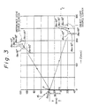
- Fig.3 shows an example of the optimization of the positions O (Y O ,Z O ) and R (Y R ,Z R ) with respect to the incident angle ⁇ in by the above mentioned mathematical programming, under the condition that the distance between the hologram disk 12 and the image surface 13 is assumed to be 300 mm. In this example, such a condition is assumed that the distance r between the point P and the center H is 35 mm, twelve holograms 11 are provided on the hologram disk 12, and the diffraction light beam 16 is moved for scanning on the image surface 13 by a scan length of 260 mm every time the reproducing light beam 15 goes across each hologram 11 in company with the rotation of the hologram disk 12.
- Fig.4 shows the scan-line bow of the diffraction light beam 16 on the image surface 13, with respect to each incident angle ⁇ in , versus the scan position on the image surface 13.
- a position of the scan position 0 corresponds to the scan center.
- the scan-line bow is within as little as 0.1 mm.
- Fig.5 shows the change of each RMS (effective value) wavefront aberration at the image surface 13 with respect to each incident angle ⁇ in , versus the scan position on the image surface 13.
- the RMS wavefront aberration is within ⁇ /14 i.e. within the tolerance of the RMS wavefront value defined as the SD (Strehl's Definition) value is not less than 80 %. That is to say, the diffraction light beam 16 having a small wavefront aberration can be obtained with respect to the whole portion of the scan line.
- Fig.6 shows a relationship between the incident angle ⁇ in of the reproducing light beam 15 and the optical path length of the diffraction light beam 16 at the scan center.
- the wavefront aberration increases and the optical path length reduces as the incident angle ⁇ in increases.
- the incident angle ⁇ in is related to the diffraction efficiency, and it is desirable to set the incident angle ⁇ in at an angle close to the Bragg angle ⁇ B in order to obtain a high diffraction efficiency.
- the Bragg angle ⁇ B is expressed by a following equation (3), where d represents the pitch of the interference fringes of the hologram and ⁇ 2 represents the wavelength of the reproducing light beam 15.
- ⁇ B sin -1 ( ⁇ 2 /(2d))
- the Bragg angle ⁇ B is calculated from the pitch d as for the hologram optimized by the aforementioned mathematical programming in its recording process with respect to each incident angle ⁇ in .
- Fig.7 shows the thus calculated Bragg angle ⁇ B versus the incident angle ⁇ in .
- the incident angle ⁇ in coincides with the Bragg angle ⁇ B when ⁇ in is about 45 degrees.
- the incident angle ⁇ in is preferably determined by taking into consideration the RMS wavefront aberration, the optical path length and the Bragg angle conditions.
- the focusing ability as well as the deflecting ability can be given to the hologram 11, with respect to the reproducing light beam 15 of a collimated type in the reproducing operation. Further because of the prescribed positioning of the positions O and R in the recording process, the reproducing light beam 15 inputted to the hologram 11 by an incident angle ⁇ in can be focused on the image surface 13 as the diffraction light beam 16, and the diffraction light beam 16 can be straightly moved on the image surface 13 in the reproducing operation.
Landscapes
- Physics & Mathematics (AREA)
- General Physics & Mathematics (AREA)
- Optics & Photonics (AREA)
- Mechanical Optical Scanning Systems (AREA)
Claims (6)
- Verfahren zum Aufzeichnen eines Hologramms (11) durch wechselseitige Interferenz von Objektlicht und Bezugslicht, mit:dadurch gekennzeichnet, dass sowohl die erste als auch die zweite Position (O, R) versetzt gegen die Mittelachse (14) der Hologrammscheibe (12) liegen.Erzeugen des Objektlichts als divergente Kugelwelle unter Verwendung einer an einer ersten Position (O) angeordneten Objektlichtquelle, und Projizieren des erzeugten Objektlichts zu einer Hologramm-Aufzeichnungsebene einer Hologrammscheibe (12), auf der das Hologramm (11) aufzuzeichnen ist, wobei die erste Position (O) um einen ersten Abstand von der Hologramm-Aufzeichnungsebene entfernt ist; undErzeugen des Bezugslichts als divergente Kugelwelle unter Verwendung einer an einer zweiten Position (R) angeordneten Bezugslichtquelle, und Projizieren des erzeugten Bezugslichts zu einer Hologramm-Aufzeichnungsebene einer Hologrammscheibe (12), auf der das Hologramm (11) aufzuzeichnen ist, wobei die zweite Position (R) um einen zweiten Abstand, der vom ersten Abstand verschieden ist, von der Hologramm-Aufzeichnungsebene entfernt ist;wobei die Objektlichtwelle und die Bezugslichtwelle kohärent sind und die Lichtquellen die jeweiligen Ursprünge der divergenten Kugelwellen sind;
- Verfahren nach Anspruch 1, bei dem die erste und die zweite Position (O, R) durch mathematische Programmierung so bestimmt werden, dass das Hologramm (11) mit wünschenswertem Fokussiervermögen und wünschenswertem Ablenkvermögen aufgezeichnet ist.
- Verfahren nach Anspruch 1 oder Anspruch 2, bei dem als genannte Objekt- und Bezugslichtquelle eine Argonlaserquelle verwendet wird.
- Holographische Abtasteinrichtung mit:einer Reproduzier-Lichtquelle (17, 18; 30, 31) zum Erzeugen eines Reproduzier-Lichtstrahls (15; 35; 135);einer Hologrammscheibe (12; 23; 123), die für Rotation ausgebildet ist; undeinem Hologramm (11; 22; 122), das auf der Hologrammscheibe angeordnet ist, um den Reproduzier-Lichtstrahl durch Beugung abzulenken, damit der abgelenkte Reproduzier-Lichtstrahl (16; 36; 136) während einer Umdrehung der Hologrammscheibe eine Bildebene (13; 24; 124) abtastet;wobei das Hologramm (11; 22; 122) durch das Verfahren nach einem der vorstehenden Ansprüche auf die Hologrammscheibe aufgezeichnet wurde.
- Holographische Abtasteinrichtung nach Anspruch 4, bei der der Reproduzier-Lichtstrahl ein kollimierter Lichtstrahl (15; 35; 135) ist.
- Holographische Abtasteinrichtung nach Anspruch 4 oder Anspruch 5, bei der die Reproduzier-Lichtquelle eine Halbleiterlaser-Quelle (17; 30) aufweist.
Priority Applications (1)
| Application Number | Priority Date | Filing Date | Title |
|---|---|---|---|
| EP01201640A EP1130447A3 (de) | 1989-12-27 | 1990-12-24 | Holographische Abtasteinrichtung und Verfahren zum Aufzeichnen und Kopieren eines Hologramms in dieser Abtasteinrichtung |
Applications Claiming Priority (3)
| Application Number | Priority Date | Filing Date | Title |
|---|---|---|---|
| JP34146989 | 1989-12-27 | ||
| JP341469/89 | 1989-12-27 | ||
| JP1341469A JP2642207B2 (ja) | 1989-12-27 | 1989-12-27 | ホログラムの記録再生方法 |
Related Child Applications (1)
| Application Number | Title | Priority Date | Filing Date |
|---|---|---|---|
| EP01201640A Division EP1130447A3 (de) | 1989-12-27 | 1990-12-24 | Holographische Abtasteinrichtung und Verfahren zum Aufzeichnen und Kopieren eines Hologramms in dieser Abtasteinrichtung |
Publications (3)
| Publication Number | Publication Date |
|---|---|
| EP0435662A2 EP0435662A2 (de) | 1991-07-03 |
| EP0435662A3 EP0435662A3 (en) | 1992-12-09 |
| EP0435662B1 true EP0435662B1 (de) | 2001-11-14 |
Family
ID=18346308
Family Applications (2)
| Application Number | Title | Priority Date | Filing Date |
|---|---|---|---|
| EP90314293A Expired - Lifetime EP0435662B1 (de) | 1989-12-27 | 1990-12-24 | Holographische Abtasteinrichtung und Verfahren zum Aufzeichnen und Reproduziereneines Hologramms in dieser Abtasteinrichtung |
| EP01201640A Withdrawn EP1130447A3 (de) | 1989-12-27 | 1990-12-24 | Holographische Abtasteinrichtung und Verfahren zum Aufzeichnen und Kopieren eines Hologramms in dieser Abtasteinrichtung |
Family Applications After (1)
| Application Number | Title | Priority Date | Filing Date |
|---|---|---|---|
| EP01201640A Withdrawn EP1130447A3 (de) | 1989-12-27 | 1990-12-24 | Holographische Abtasteinrichtung und Verfahren zum Aufzeichnen und Kopieren eines Hologramms in dieser Abtasteinrichtung |
Country Status (4)
| Country | Link |
|---|---|
| US (1) | US5172252A (de) |
| EP (2) | EP0435662B1 (de) |
| JP (1) | JP2642207B2 (de) |
| DE (1) | DE69033854T2 (de) |
Families Citing this family (5)
| Publication number | Priority date | Publication date | Assignee | Title |
|---|---|---|---|---|
| EP1111429B1 (de) * | 1991-03-27 | 2006-03-08 | Fujitsu Limited | Lichtabtastvorrichtung |
| EP0553503A2 (de) * | 1992-01-28 | 1993-08-04 | Opticon Sensors Europe B.V. | Verfahren zur Aufzeichnung eines Hologrammes für einen optischen Abtaster |
| JP3418985B2 (ja) * | 1992-12-14 | 2003-06-23 | 株式会社デンソー | 画像表示装置 |
| US5621548A (en) * | 1995-03-31 | 1997-04-15 | Eastman Kodak Company | Laser scanner employing a holeless hologon disk and fabrication method therefor |
| AU2002361857A1 (en) * | 2001-12-19 | 2003-07-09 | Actuality Systems, Inc. | A radiation conditioning system |
Citations (1)
| Publication number | Priority date | Publication date | Assignee | Title |
|---|---|---|---|---|
| EP0334631A2 (de) * | 1988-03-25 | 1989-09-27 | Fujitsu Limited | Lichtbündelabtaster |
Family Cites Families (10)
| Publication number | Priority date | Publication date | Assignee | Title |
|---|---|---|---|---|
| US4266846A (en) * | 1976-12-28 | 1981-05-12 | University Of Delaware | Two-dimensional scanners |
| JPS59191007A (ja) * | 1983-04-13 | 1984-10-30 | Fujitsu Ltd | 光ビ−ム走査方法 |
| JPS6042733A (ja) * | 1983-08-18 | 1985-03-07 | Yokogawa Hokushin Electric Corp | ホログラムを用いた光走査装置 |
| JPS60238885A (ja) * | 1984-05-14 | 1985-11-27 | Fujitsu Ltd | ホログラム記録方法 |
| JPS61282819A (ja) * | 1985-06-07 | 1986-12-13 | Ricoh Co Ltd | 光偏向用ホログラムデイスク |
| US4923262A (en) * | 1985-11-06 | 1990-05-08 | Holographix, Inc. | Scanner system having rotating deflector hologram |
| EP0223508A3 (de) * | 1985-11-06 | 1987-10-14 | Holographix, Inc. | Abtastsystem mit einem rotierenden Hologrammm als Ablenkvorrichtung |
| JPH071350B2 (ja) * | 1986-03-10 | 1995-01-11 | 富士通株式会社 | レ−ザ光走査装置 |
| JPS6321620A (ja) * | 1986-07-15 | 1988-01-29 | Mitsubishi Electric Corp | ホログラムスキヤナおよびその製造方法 |
| JP2767588B2 (ja) * | 1988-03-25 | 1998-06-18 | 富士通株式会社 | 光ビーム走査装置 |
-
1989
- 1989-12-27 JP JP1341469A patent/JP2642207B2/ja not_active Expired - Fee Related
-
1990
- 1990-12-21 US US07/632,392 patent/US5172252A/en not_active Expired - Lifetime
- 1990-12-24 DE DE69033854T patent/DE69033854T2/de not_active Expired - Lifetime
- 1990-12-24 EP EP90314293A patent/EP0435662B1/de not_active Expired - Lifetime
- 1990-12-24 EP EP01201640A patent/EP1130447A3/de not_active Withdrawn
Patent Citations (1)
| Publication number | Priority date | Publication date | Assignee | Title |
|---|---|---|---|---|
| EP0334631A2 (de) * | 1988-03-25 | 1989-09-27 | Fujitsu Limited | Lichtbündelabtaster |
Non-Patent Citations (1)
| Title |
|---|
| PATENT ABSTRACTS OF JAPAN, vol. 10, no. 106 (P-449), 22nd April 1986; & JP-A-60 238 885 (FUJITSU K.K.) 27-11-1985 * |
Also Published As
| Publication number | Publication date |
|---|---|
| DE69033854T2 (de) | 2002-06-13 |
| US5172252A (en) | 1992-12-15 |
| EP0435662A2 (de) | 1991-07-03 |
| JP2642207B2 (ja) | 1997-08-20 |
| EP1130447A2 (de) | 2001-09-05 |
| DE69033854D1 (de) | 2001-12-20 |
| JPH03198018A (ja) | 1991-08-29 |
| EP1130447A3 (de) | 2004-11-10 |
| EP0435662A3 (en) | 1992-12-09 |
Similar Documents
| Publication | Publication Date | Title |
|---|---|---|
| EP0132956B1 (de) | Abtastvorrichtung für Lichtstrahl | |
| US6847472B2 (en) | Optical scanning device image forming apparatus and optical scanning method | |
| US4957336A (en) | Laser beam scanner and its fabricating method | |
| AU714216B2 (en) | Optical beam scanning apparatus, and method for manufacturing stationary hologram plate, and hologram rotor, and optical wiring apparatus | |
| US4973112A (en) | Hologon deflection system having dispersive optical elements for scan line bow correction, wavelength shift correction and scanning spot ellipticity correction | |
| EP0539226A1 (de) | Optischer Abtaster mit einem Laserstrahl | |
| US4639071A (en) | Light scanning apparatus | |
| US4753502A (en) | Holographic laser beam scanner | |
| EP0435662B1 (de) | Holographische Abtasteinrichtung und Verfahren zum Aufzeichnen und Reproduziereneines Hologramms in dieser Abtasteinrichtung | |
| JPH0521210B2 (de) | ||
| JPH0524490B2 (de) | ||
| JP2571638B2 (ja) | ホログラムスキャナ | |
| US6292278B1 (en) | Beam scanning system adopting deflection disc | |
| JP2740665B2 (ja) | ホログラフィックfθレンズ作成方法 | |
| JPH05313091A (ja) | ホログラムスキャナ | |
| JP2791449B2 (ja) | ホログラムスキャナ | |
| JPH0617949B2 (ja) | ホログラムスキャナ | |
| JPH04204413A (ja) | 光走査装置 | |
| JPH0535871B2 (de) | ||
| JPH08313840A (ja) | 光走査装置 | |
| JPH08146335A (ja) | 光走査装置 | |
| JPS5814114A (ja) | ホログラム光走査器 | |
| JPH02205815A (ja) | 光走査装置 | |
| JPS5821225A (ja) | 光走査装置 | |
| JPH05203892A (ja) | 光ビーム走査装置 |
Legal Events
| Date | Code | Title | Description |
|---|---|---|---|
| PUAI | Public reference made under article 153(3) epc to a published international application that has entered the european phase |
Free format text: ORIGINAL CODE: 0009012 |
|
| 17P | Request for examination filed |
Effective date: 19910102 |
|
| AK | Designated contracting states |
Kind code of ref document: A2 Designated state(s): DE FR GB |
|
| K1C3 | Correction of patent application (complete document) published |
Effective date: 19910703 |
|
| PUAL | Search report despatched |
Free format text: ORIGINAL CODE: 0009013 |
|
| AK | Designated contracting states |
Kind code of ref document: A3 Designated state(s): DE FR GB |
|
| 17Q | First examination report despatched |
Effective date: 19950316 |
|
| GRAG | Despatch of communication of intention to grant |
Free format text: ORIGINAL CODE: EPIDOS AGRA |
|
| GRAG | Despatch of communication of intention to grant |
Free format text: ORIGINAL CODE: EPIDOS AGRA |
|
| GRAH | Despatch of communication of intention to grant a patent |
Free format text: ORIGINAL CODE: EPIDOS IGRA |
|
| GRAH | Despatch of communication of intention to grant a patent |
Free format text: ORIGINAL CODE: EPIDOS IGRA |
|
| GRAA | (expected) grant |
Free format text: ORIGINAL CODE: 0009210 |
|
| AK | Designated contracting states |
Kind code of ref document: B1 Designated state(s): DE FR GB |
|
| PG25 | Lapsed in a contracting state [announced via postgrant information from national office to epo] |
Ref country code: FR Free format text: LAPSE BECAUSE OF FAILURE TO SUBMIT A TRANSLATION OF THE DESCRIPTION OR TO PAY THE FEE WITHIN THE PRESCRIBED TIME-LIMIT Effective date: 20011114 |
|
| REF | Corresponds to: |
Ref document number: 69033854 Country of ref document: DE Date of ref document: 20011220 |
|
| REG | Reference to a national code |
Ref country code: GB Ref legal event code: IF02 |
|
| PG25 | Lapsed in a contracting state [announced via postgrant information from national office to epo] |
Ref country code: GB Free format text: LAPSE BECAUSE OF NON-PAYMENT OF DUE FEES Effective date: 20020214 |
|
| PLBE | No opposition filed within time limit |
Free format text: ORIGINAL CODE: 0009261 |
|
| STAA | Information on the status of an ep patent application or granted ep patent |
Free format text: STATUS: NO OPPOSITION FILED WITHIN TIME LIMIT |
|
| EN | Fr: translation not filed | ||
| GBPC | Gb: european patent ceased through non-payment of renewal fee |
Effective date: 20020214 |
|
| 26N | No opposition filed | ||
| PGFP | Annual fee paid to national office [announced via postgrant information from national office to epo] |
Ref country code: DE Payment date: 20091217 Year of fee payment: 20 |
|
| PG25 | Lapsed in a contracting state [announced via postgrant information from national office to epo] |
Ref country code: DE Free format text: LAPSE BECAUSE OF EXPIRATION OF PROTECTION Effective date: 20101224 |