EP0434286B1 - Bildübertragungsgerät - Google Patents
Bildübertragungsgerät Download PDFInfo
- Publication number
- EP0434286B1 EP0434286B1 EP90313475A EP90313475A EP0434286B1 EP 0434286 B1 EP0434286 B1 EP 0434286B1 EP 90313475 A EP90313475 A EP 90313475A EP 90313475 A EP90313475 A EP 90313475A EP 0434286 B1 EP0434286 B1 EP 0434286B1
- Authority
- EP
- European Patent Office
- Prior art keywords
- recording paper
- chassis
- bearings
- transport path
- guide plate
- Prior art date
- Legal status (The legal status is an assumption and is not a legal conclusion. Google has not performed a legal analysis and makes no representation as to the accuracy of the status listed.)
- Expired - Lifetime
Links
- 239000000088 plastic resin Substances 0.000 description 6
- 239000002184 metal Substances 0.000 description 5
- 230000005540 biological transmission Effects 0.000 description 4
- 238000010276 construction Methods 0.000 description 3
- 239000006185 dispersion Substances 0.000 description 2
- 230000005611 electricity Effects 0.000 description 1
- 238000003754 machining Methods 0.000 description 1
- 239000012811 non-conductive material Substances 0.000 description 1
- 230000003068 static effect Effects 0.000 description 1
- 238000011144 upstream manufacturing Methods 0.000 description 1
Images


Classifications
-
- H—ELECTRICITY
- H04—ELECTRIC COMMUNICATION TECHNIQUE
- H04N—PICTORIAL COMMUNICATION, e.g. TELEVISION
- H04N1/00—Scanning, transmission or reproduction of documents or the like, e.g. facsimile transmission; Details thereof
- H04N1/00519—Constructional details not otherwise provided for, e.g. housings, covers
Definitions
- the present invention relates to an image communication device.
- Prior art Image communication devices generally comprise a plurality of rollers for transporting and ejecting original documents to be read for transmission, a plurality of rollers for transporting and ejecting recording paper on which to record data, and latches by which to keep the device cover closed.
- the roller and latch shafts are secured by a chassis with side plates on both sides thereof.
- the side plates have a plurality of through holes through which to pass the bearings supporting the roller and latch shafts.
- the shafts are first inserted into the through holes.
- the shafts and the through holes are then equipped with the bearings from outside the side plates. This positions each shaft on the chassis. Gears, latches and other related parts are inserted onto the shafts and are ultimately fixed thereto with E rings and screws.
- the chassis is made of metal.
- European Patent application EP-A- 299437 discloses a facsimile with u-turn feed means, having a turnabout roller for changing an original-sheet lead direction, a reading sensor contained in the body cover to read an image and image reading means contained in the body cover to record an image on a recording sheet, the principle object being to reduce the mounting space for the u-turn feed means and image reading sensor.
- One disadvantage of the above-described prior art construction is that the assembling of the roller and latch shafts tends to become complicated and requires increasing numbers of steps.
- Plastic resin chassis have recently been developed and utilized for cost reduction purposes.
- One disadvantage of using the plastic resin chassis is that the roller shafts fail to be connected to ground. The static electricity trapped in the rollers sometimes results in such troubles as jammed and otherwise feed-disrupted documents.
- the image communication device of the invention comprises a lower chassis, a document transport means mounted on said lower chassis and defining a document transport path extending from an upper portion of one end of said device to a lower portion of the other end of the device, whereby a space is left above said lower portion and below a level of the top of said device;
- the present invention therefore provides an image communication device which is easy to assemble in a small number of steps.
- the present invention further provides an image communication device whose chassis has side plates to which a plurality of rollers are easily attached.
- the present invention further provides an image communication device which, despite its use of nonconductive chassis, allows the rollers to be connected to ground in a simple manner.
- the present invention even further provides an image communication device whose latch shaft is easily attached to the chassis.
- a guide plate for guiding original documents is fixedly mounted on the chassis.
- the guide plate has projections that press the bearings in the recesses against the bottom thereof.
- chassis is made of a nonconductive material such as a plastic resin
- the recesses have one end therefore opened onto the two side plates and comprise, at their bottom, curved portions for accommodating the shafts.
- the projections engage with the shafts held by the recesses so that the shafts are securely positioned in the curved portions. Simply pushing the shafts into the curved portions at the bottom of the recesses causes the positioning projections to secure the shafts inside the curved portions with no screws. In this manner, the shafts are mounted easily.
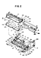
- the image communication device embodying the present invention comprises a housing 1, a cover 2 movably mounted on the housing 1 and a base (i.e. lower) chassis 10 accommodated inside the housing 1.
- the base chassis 10 has side plates 10A on both sides thereof and a bottom plate 10B that connects the side plates 10A.
- the base chassis 10 may be made of a metal but should preferably be of a plastic resin.
- a plastic resin base chassis 10 has an advantage of being produced at low cost.
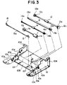
- the base chassis 10 has an introducing roller 11, a feed roller 12, a reading roller 13 and an ejection roller 14 rotatably mounted on conductive bearings 11a, 12a, 13a and 14a, respectively.
- the introducing roller 11 introduces original documents into the device; the feed roller 12 forwards the introduced original; the reading roller 13 positions the original to a reading point inside; and the ejection roller 14 ejects the original out of the device.
- the bearings lla through 14a are usually made of a metal but may be constituted by a conductive plastic resin or the like.
- the introducing roller 11 is equipped with an introducing roller gear 11b that transmits the torque of a driving motor, not shown, to the introducing roller.
- the feed roller 12 is equipped with a feed roller gear 12b and a driving power transmission gear 12c for transmitting the torque of a driving motor, not shown, to the feed roller.
- the reading roller 13 To the reading roller 13 are attached a reading roller gear 13b and a driving power transmission pulley 13c, both engaged with the driving power transmission gear 12c.
- a pulley 14b is attached to the ejection roller 14.
- a belt, not shown, is held taut between pulleys 13c and 14b so that the revolutions of the pulley 13c are transmitted to the pulley 14b.
- the rollers 11 through 14 constitute a document transport means in the transmitting section of the device.
- the base chassis 10 further comprises a latch shaft 15a, both ends of which have latches 15 for keeping the cover 2 on top of the device closed.
- the side plates 10 of the base chassis 10 have recesses 10a, 10b, 10c and 10d. Each of these recesses is opened at its top on the side plates 10A.
- the bearings and gears attached to the rollers simply inserting the bearings from the top openings of these recesses seats the bearings at the recess bottom and sets the rollers in place. This significantly facilitates the assembling of the rollers on the device.
- the side plates 10A of the base chassis 10 further comprise recesses 10e which are opened at their top and which accommodate the latch shaft 15a.
- a bottom plate 10B has positioning projections 10f at points that come into contact with the latch shaft 15a supported by the recesses 10e.
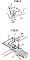
- Fig. 4 illustrates how the recess 10e and positioning projections 10f are seen in the axial direction of the latch shaft 15a.
- a gap ⁇ formed between the positioning projections 10f and the recesses 10e opposed thereto is designed to be smaller than the diameter of the latch shaft 15a.
- those bottoms of the recesses 10e which are opposite to the positioning projections 10f have curved portions 10g that match the circumference of the latch shaft 15a.
- a guide plate 16 made of metal is screwed or otherwise attached to the base chassis 10, the plate guiding original documents from upstream to downstream of the introducing roller 11.
- projections 16a and 16b equipped respectively with conductive elastic members 16c and 16d, illustratively made of a conductive rubber.
- the projections 16a and 16b together with the conductive elastic members 16c and 16d are positioned so that when the guide plate 16 is mounted on the appropriate position of the base chassis 10, the projections and their elastic members contact and secure the bearings 11a and 12a on the chassis 10.
- the conductive elastic members 16c and 16d are provided so as to absorb any dispersion in machined size or distortion of the guide plate 16.
- the projections 16a and 16b may contact firmly and secure the bearings 11a and 12a while making the guide plate 16 conductive at the same time. If the guide plate 16 is machined with more precision, or if the guide plate 16 is capable of absorbing dimensional dispersion or deformation on its own, the conductive elastic members may be omitted and the projections 16a and 16b may be allowed to contact directly the bearings 11a and 12a.
- a stay 17 made of metal is further attached to the base chassis 10.
- the stay 17 has on both sides thereof projections 17a equipped with conductive elastic members 17b.
- the elastic members 17b contact and secure the bearings 14a.
- Plate springs 17c are attached to notches of the stay 17 and, during assembling, come into contact and secure the bearings 13a.
- the guide plate 16 and the stay 17 are in contact with and grounded to plate springs, not shown, which in turn are connected to round.
- the receiving block 18 comprises a receiving (i.e., upper) chassis 18A.
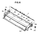
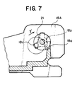
- the receiving chassis 18A in turn contains a platen roller 19 for transporting recording paper, a platen roller gear 19a for driving the platen roller 19, a cutter 20 for cutting the recording paper, an ejection roller 21 for ejecting the recording paper, an ejection roller gear 21a for driving the ejection roller 21, and an idler gear 22 for connecting the platen roller gear 19a to the ejection roller gear 21a.
- the receiving chassis 18A is shaped as depicted in Fig. 6. close to the position where the ejection roller 21 is mounted exist ribs 18a.
- the side plates on both sides have holes 18b through which to insert the ejection roller 21.
- both ends of the roller are inserted into the holes 18b one side at a time from within, and then the bearings 21b are inserted and secured from the outside.
- inserting the ejection roller 21 into the center of each hole 18b would cause interference with the ribs 18a of the receiving chassis 18A.
- Such interference is circumvented by this embodiment having notches 18c made in the holes 18b of the side plates.
- both ends of the ejection roller 21 are inserted into the notches 18c one side at a time.
- the ejection roller 21 is moved in the arrowed direction ⁇ to the center of the holes 18b. Then the bearings 21b are inserted and secured from the outside. This allows the ejection roller 21 to be mounted with no interference with the ribs 18a.
- the ribs 18a are designed to prevent the recording paper with received data recorded thereon from getting rewound into the device by the ejection roller 21.
- Figs. 8 and 9 show how the idler gear 22 is illustratively mounted.
- the idler gear 22 Rotatably attached to a shaft 22A, the idler gear 22 has a plurality of projections 22a inside.
- the shaft 22A has a circular groove 22b on its circumference.
- the minimum inner diameter of the projections 22a is smaller than the outer diameter of the shaft 22A.
- forcing the idler gear 22 onto the shaft 22A puts the projections 22a into the circular groove 22b.
- the idler gear 2?2 is restricted in terms of thrust by the projections 22a while freely rotating around the shaft 22A. This makes it very easy to assemble the idler gear 22.
- the idler gear 22 may be rotatably attached to the shaft 22A by use of a conventional E ring for thrust restriction.
- a freely rotating pinch roller 23 is located above and pressed against the feed roller 12. Under the reading roller 13 is a contact-type Image sensor unit 24 that reads original documents being fed. Another freely rotating pinch roller 25 is located below and pressed against the ejection roller 14.
- the front end of the device has a section that accommodates a roll of recording paper 26.
- a thermal head 27 that prints data on the recording paper in conjunction with the platen roller 19.
- Another freely rotating pinch roller 28 is located above the ejection roller 21.
- the bearings 11a, 12a, 13a and 14a are inserted into the introducing roller 11, feed roller 12, reading roller 13 and ejection roller 14, respectively.
- the bearings are inserted through the top openings of the recesses 10a, 10b, 10c and 10d formed on the side plates 10A of the base chassis 10. The bearings are thus seated on the bottom of each recess.
- the latch shaft 15a is placed on the recesses 10e and pressed downward for entry thereinto. With ist center deflected, the latch shaft 15a is secured in the curved portions 10g at the bottom.
- the guide plate 16 and the stay 17 are then screwed to the base chassis 10. This allows the conductive elastic members 16c, 16d and 17d mounted on the projections of the guide plate 16 and stay 17 to contact and secure the bearings 11a, 12a and 14a (see Fig. 5).
- the plate springs 17c of the stay 17 come into contact with and secures the bearings 13a. That is, simply attaching the guide plate 16 and the stay 17 secures the bearings in their respective positions. Since the members 16c, 16d and 17d as well as the plate springs 17c mounted on the guide plate 16 and stay 17 are elastic, these parts firmly fix the bearings by absorbing any dimensional irregularities that may have occurred to the guide plate 16 or stay 17 during machining or assembling. Attaching the guide plate 16 and stay 17 allows the bearings to conduct via the conductive elastic members and the plate springs 17c. It follows that the rollers conduct to the guide plate 16 and stay 17. Thus it is easy to connect each of the rollers to ground.
- the block With the platen roller 19, cutter 20, ejection roller 21 and idler gear 22 built into the receiving block 18, the block is screwed or otherwise attached to the base chassis 10. In the manner described, the key parts of the device are readily assembled.
- original documents to be transmitted are set on a document table on top of the device so that the lower edge of the lowermost document is located between the introducing roller 11 and a sheet-separating member pressed thereagainst.
- the introducing roller 11 supplies one document at a time from the document table into the device.
- the feed roller 12 and pinch roller 23 forward the document.
- the unit 24 reads the document.
- the image data thus read is transmitted by a transmitting means, not shown. Thereafter, the document is ejected to the front of the device by the ejection roller 14 and ejection pinch roller 25.
- the platen roller 29 Upon receipt of data, the platen roller 29 pulls out the tip of the recording paper roll 26. The received data is printed on the recording paper with the thermal head 27. The recorded paper is expected out of the device by the ejection roller 21 and pinch roller 28, and a cutter 20 cuts the ending margin of the recorded portion of the paper. The cut and ejected sheets are stacked at the top of the device.
Landscapes
- Engineering & Computer Science (AREA)
- Multimedia (AREA)
- Signal Processing (AREA)
- Facsimiles In General (AREA)
- Delivering By Means Of Belts And Rollers (AREA)
- Feeding Of Articles By Means Other Than Belts Or Rollers (AREA)
Claims (6)
- Bildübertragungsvorrichtung, die umfaßt:ein unteres Gestell (10);eine Dokumententransporteinrichtung (11, 12, 13, 14), die an dem unteren Gestell angebracht ist und einen Dokumententransportweg bildet, der von einem oberen Abschnitt eines Endes der Vorrichtung zu einem unteren Abschnitt des anderen Endes der Vorrichtung verläuft, wobei ein Zwischenraum oberhalb des unteren Abschnitts und unterhalb einer Höhe der Oberseite der Vorrichtung verbleibt;eine Dokumentenleseeinrichtung (24), die unter einem Mittelabschnitt des Dokumententransportweges angebracht ist und die Bilder auf einem mit der Oberseite nach unten liegenden Dokument liest, das darauf transportiert wird;ein oberes Gestell (18A), das am oberen Teil des unteren Gestells (10) angebracht ist;eine Aufzeichnungspapier-Transporteinrichtung (19,21), die in dem oberen Gestell (18A) angebracht ist und einen Aufzeichnungspapier-Transportweg bildet, der von dem anderen Ende der Vorrichtung zu dem einen Ende der Vorrichtung im allgemeinen parallel zu dem Dokumententransportweg und oberhalb des Dokumententransportweges verläuft und kurz vor dem einen Ende der Vorrichtung endet;eine Aufzeichnungseinrichtung (27), die oberhalb des Aufzeichnungspapier-Transportweges angebracht ist, und die Daten auf eine nach oben gerichtete Fläche von Transportpapier aufzeichnet, das auf dem Aufzeichnungspapier-Transportweg transportiert wird;eine Aufzeichnungspapier-Schneideinrichtung (20) an dem oberen Gestell (18A) an einem Ende des Aufzeichnungspapier-Transportweges in Richtung des einen Endes der Vorrichtung; undeinen Aufzeichnungspapierhalter an dem anderen Ende der Vorrichtung in dem Raum oberhalb des Dokumententransportweges, der eine Rolle Aufzeichnungspapier (26) hält und der Aufzeichnungspapier-Transporteinrichtung (19,21) Aufzeichnungspapier zuführt.
- Vorrichtung nach Anspruch 1, wobei das untere Gestell ein Paar aufrechtstehender Seitenplatten (10A) und eine Bodenplatte (10B) aufweist, die die Seitenplatten verbindet, wobei die Seitenplatten eine Vielzahl von Aussparungen (10a-10d) aufweisen, die an ihren Oberseiten offen sind, und die Dokumententransporteinrichtung eine Vielzahl von Rollen (11, 12, 13, 14) zum Transport von Dokumenten und Lager (11a-14a) an den Rollen aufweist, wobei die Aussparungen die Lager darin aufnehmen, um die Rollen drehbar zu tragen.
- Vorrichtung nach Anspruch 2, die des weiteren eine Führungsplatte (16) umfaßt, die fest an dem unteren Gestell (10) angebracht ist und Dokumente in die Dokumententransporteinrichtung leitet, wobei die Führungsplatte eine Vielzahl von Vorsprüngen (16a, 16b) daran aufweist, die wenigstens einige der Lager an die Böden der Aussparungen (10a-10d) drückt, in denen die Lager aufgenommen sind.
- Vorrichtung nach Anspruch 3, wobei die Lager (11a-14a) und die Führungsplatte (16) elektrisch leitend sind, und die des weiteren Einrichtungen umfaßt, die die Führungsplatte elektrisch mit Masse verbinden, so daß die Rollen über die Führungsplatte geerdet sind.
- Vorrichtung nach Anspruch 4, wobei die Vorsprünge eine Vielzahl leitender elastischer Elemente (16c, 16d) daran aufweisen, die mit den Lagern (11a-14a) in Kontakt sind.
- Vorrichtung nach einem der Ansprüche 2-5, die des weiteren eine Einrastklinkenwelle (15a) umfaßt, deren beide Enden durch das untere Gestell (10) getragen werden, und die einen Einrastklinkenmechanismus daran aufweist, wobei die Seitenplatten (10A) des unteren Gestells weitere Aussparungen (10e) darin aufweisen, die an der Oberseite offen sind und jeweils eine Seitenwand mit einem bogenförmigen Abschnitt (10g) am Boden derselben aufweisen, wobei die Einrastklinkenwelle (15a) in den bogenförmigen Abschnitten (10g) positioniert ist, und die Bodenplatte (10B) Vorsprünge daran aufweist, die mit der Einrastklinkenwelle in Kontakt sind und die Einrastklinkenwelle in die bogenförmigen Abschnitte drücken.
Applications Claiming Priority (2)
| Application Number | Priority Date | Filing Date | Title |
|---|---|---|---|
| JP1327917A JPH03192044A (ja) | 1989-12-18 | 1989-12-18 | 画像通信装置 |
| JP327917/89 | 1989-12-18 |
Publications (3)
| Publication Number | Publication Date |
|---|---|
| EP0434286A2 EP0434286A2 (de) | 1991-06-26 |
| EP0434286A3 EP0434286A3 (en) | 1992-06-03 |
| EP0434286B1 true EP0434286B1 (de) | 1996-03-27 |
Family
ID=18204444
Family Applications (1)
| Application Number | Title | Priority Date | Filing Date |
|---|---|---|---|
| EP90313475A Expired - Lifetime EP0434286B1 (de) | 1989-12-18 | 1990-12-11 | Bildübertragungsgerät |
Country Status (4)
| Country | Link |
|---|---|
| US (1) | US5295002A (de) |
| EP (1) | EP0434286B1 (de) |
| JP (1) | JPH03192044A (de) |
| DE (1) | DE69026221T2 (de) |
Families Citing this family (7)
| Publication number | Priority date | Publication date | Assignee | Title |
|---|---|---|---|---|
| JPH06350792A (ja) * | 1993-06-10 | 1994-12-22 | Canon Inc | ファクシミリ装置 |
| JP3169745B2 (ja) * | 1993-06-30 | 2001-05-28 | 松下電送システム株式会社 | ファクシミリ装置 |
| US5870210A (en) * | 1997-02-06 | 1999-02-09 | Chang; Shyi-Huang | Feed roller assembly of a fax machine |
| JP4734969B2 (ja) * | 2005-03-04 | 2011-07-27 | 船井電機株式会社 | レーザビームプリンタ装置 |
| JP2007119096A (ja) * | 2005-10-25 | 2007-05-17 | Kyocera Mita Corp | 画像形成装置のユニット、画像形成装置および自動給紙装置 |
| JP6235252B2 (ja) * | 2013-07-04 | 2017-11-22 | Necプラットフォームズ株式会社 | 原稿送り装置及び原稿送り装置の組み立て方法 |
| JP7129827B2 (ja) * | 2018-06-13 | 2022-09-02 | キヤノン電子株式会社 | 画像読取装置 |
Family Cites Families (7)
| Publication number | Priority date | Publication date | Assignee | Title |
|---|---|---|---|---|
| DE3404799A1 (de) * | 1983-02-10 | 1984-08-16 | Ricoh Co., Ltd., Tokio/Tokyo | Faksimilegeraet |
| US4729036A (en) * | 1984-12-04 | 1988-03-01 | Canon Kabushiki Kaisha | Original reading apparatus and original reading and recording apparatus using the same |
| JPS62100069A (ja) * | 1985-10-25 | 1987-05-09 | Sharp Corp | 折り畳み式ファクシミリ |
| US4750046A (en) * | 1986-11-04 | 1988-06-07 | Primages, Inc. | Read-write apparatus |
| JPS6410775A (en) * | 1987-07-02 | 1989-01-13 | Tokyo Electric Co Ltd | Original reader |
| US4872061A (en) * | 1987-07-13 | 1989-10-03 | Tokyo Electric Co., Ltd. | Facsimile |
| US5010441A (en) * | 1990-01-24 | 1991-04-23 | Xerox Corporation | Grounding brush |
-
1989
- 1989-12-18 JP JP1327917A patent/JPH03192044A/ja active Pending
-
1990
- 1990-12-11 DE DE69026221T patent/DE69026221T2/de not_active Expired - Fee Related
- 1990-12-11 EP EP90313475A patent/EP0434286B1/de not_active Expired - Lifetime
-
1992
- 1992-06-16 US US07/899,038 patent/US5295002A/en not_active Expired - Fee Related
Also Published As
| Publication number | Publication date |
|---|---|
| JPH03192044A (ja) | 1991-08-21 |
| EP0434286A3 (en) | 1992-06-03 |
| DE69026221T2 (de) | 1996-10-10 |
| US5295002A (en) | 1994-03-15 |
| DE69026221D1 (de) | 1996-05-02 |
| EP0434286A2 (de) | 1991-06-26 |
Similar Documents
| Publication | Publication Date | Title |
|---|---|---|
| EP0579477B1 (de) | Papierschneidgerät mit beweglichem Rundmesser | |
| EP0854627B1 (de) | Rahmenaufbau von einer Dokumenteneingabevorrichtung | |
| US7731179B2 (en) | Sheet tray assembly | |
| HK1001000B (en) | Paper cutting device using a movable cutting wheel | |
| EP0434286B1 (de) | Bildübertragungsgerät | |
| US7380787B2 (en) | Paper transportation device | |
| JPH0238496B2 (de) | ||
| JP2008213979A (ja) | 画像記録装置 | |
| US8152379B2 (en) | Bearing device having backlash reducer for reducing play of bearing, and image recording apparatus including the bearing device | |
| CA1167560A (en) | Facsimile method and apparatus | |
| US6454477B1 (en) | Sheet transport device and recording apparatus | |
| JP2562709B2 (ja) | 印字ヘッドの保持構造 | |
| JP2007136802A (ja) | 記録装置 | |
| EP1031886B1 (de) | Apparat für Bildherstellung | |
| JP2023016162A (ja) | シート搬送装置、画像形成装置 | |
| JP3268324B2 (ja) | 記録装置 | |
| JP7606166B2 (ja) | 画像読取装置 | |
| JPH0392374A (ja) | 熱印字式印刷装置を具備する画像処理機 | |
| JP2787961B2 (ja) | 原稿読取搬送機構 | |
| JPH05338834A (ja) | 原稿分離送給装置 | |
| JP2971617B2 (ja) | 自動給紙装置 | |
| JPH04260548A (ja) | 原稿読取搬送機構 | |
| JP3564907B2 (ja) | 記録装置 | |
| JP3363468B2 (ja) | ファクシミリ装置のロール状シートホルダ | |
| JP2665282B2 (ja) | 媒体送り装置 |
Legal Events
| Date | Code | Title | Description |
|---|---|---|---|
| PUAI | Public reference made under article 153(3) epc to a published international application that has entered the european phase |
Free format text: ORIGINAL CODE: 0009012 |
|
| AK | Designated contracting states |
Kind code of ref document: A2 Designated state(s): DE FR GB |
|
| RIN1 | Information on inventor provided before grant (corrected) |
Inventor name: SATO, MASANORI Inventor name: YAMADA, HIROYUKI Inventor name: TAKAMIZAWA, SHIRO Inventor name: KUMANO, TOSHIHIRO Inventor name: ISHII, YUJI |
|
| PUAL | Search report despatched |
Free format text: ORIGINAL CODE: 0009013 |
|
| AK | Designated contracting states |
Kind code of ref document: A3 Designated state(s): DE FR GB |
|
| 17P | Request for examination filed |
Effective date: 19920717 |
|
| 17Q | First examination report despatched |
Effective date: 19931125 |
|
| GRAA | (expected) grant |
Free format text: ORIGINAL CODE: 0009210 |
|
| AK | Designated contracting states |
Kind code of ref document: B1 Designated state(s): DE FR GB |
|
| RIN1 | Information on inventor provided before grant (corrected) |
Inventor name: SATO, MASANORI Inventor name: YAMADA, HIROYUKI Inventor name: TAKAMIZAWA, SHIRO Inventor name: KUMANO, TOSHIHIRO Inventor name: ISHII, YUJI |
|
| REF | Corresponds to: |
Ref document number: 69026221 Country of ref document: DE Date of ref document: 19960502 |
|
| ET | Fr: translation filed | ||
| PLBE | No opposition filed within time limit |
Free format text: ORIGINAL CODE: 0009261 |
|
| STAA | Information on the status of an ep patent application or granted ep patent |
Free format text: STATUS: NO OPPOSITION FILED WITHIN TIME LIMIT |
|
| 26N | No opposition filed | ||
| PGFP | Annual fee paid to national office [announced via postgrant information from national office to epo] |
Ref country code: DE Payment date: 20001204 Year of fee payment: 11 |
|
| PGFP | Annual fee paid to national office [announced via postgrant information from national office to epo] |
Ref country code: GB Payment date: 20001206 Year of fee payment: 11 |
|
| PGFP | Annual fee paid to national office [announced via postgrant information from national office to epo] |
Ref country code: FR Payment date: 20001212 Year of fee payment: 11 |
|
| PG25 | Lapsed in a contracting state [announced via postgrant information from national office to epo] |
Ref country code: GB Free format text: LAPSE BECAUSE OF NON-PAYMENT OF DUE FEES Effective date: 20011211 |
|
| REG | Reference to a national code |
Ref country code: GB Ref legal event code: IF02 |
|
| PG25 | Lapsed in a contracting state [announced via postgrant information from national office to epo] |
Ref country code: DE Free format text: LAPSE BECAUSE OF NON-PAYMENT OF DUE FEES Effective date: 20020702 |
|
| GBPC | Gb: european patent ceased through non-payment of renewal fee |
Effective date: 20011211 |
|
| PG25 | Lapsed in a contracting state [announced via postgrant information from national office to epo] |
Ref country code: FR Free format text: LAPSE BECAUSE OF NON-PAYMENT OF DUE FEES Effective date: 20020830 |
|
| REG | Reference to a national code |
Ref country code: FR Ref legal event code: ST |