EP0433704B1 - Lautsprecheraufnahmegehäuse - Google Patents
Lautsprecheraufnahmegehäuse Download PDFInfo
- Publication number
- EP0433704B1 EP0433704B1 EP90122510A EP90122510A EP0433704B1 EP 0433704 B1 EP0433704 B1 EP 0433704B1 EP 90122510 A EP90122510 A EP 90122510A EP 90122510 A EP90122510 A EP 90122510A EP 0433704 B1 EP0433704 B1 EP 0433704B1
- Authority
- EP
- European Patent Office
- Prior art keywords
- housing parts
- adhesive
- housing
- loudspeaker
- another
- Prior art date
- Legal status (The legal status is an assumption and is not a legal conclusion. Google has not performed a legal analysis and makes no representation as to the accuracy of the status listed.)
- Expired - Lifetime
Links
Images


Classifications
-
- H—ELECTRICITY
- H04—ELECTRIC COMMUNICATION TECHNIQUE
- H04R—LOUDSPEAKERS, MICROPHONES, GRAMOPHONE PICK-UPS OR LIKE ACOUSTIC ELECTROMECHANICAL TRANSDUCERS; ELECTRIC HEARING AIDS; PUBLIC ADDRESS SYSTEMS
- H04R1/00—Details of transducers, loudspeakers or microphones
- H04R1/02—Casings; Cabinets ; Supports therefor; Mountings therein
- H04R1/021—Casings; Cabinets ; Supports therefor; Mountings therein incorporating only one transducer
-
- H—ELECTRICITY
- H04—ELECTRIC COMMUNICATION TECHNIQUE
- H04R—LOUDSPEAKERS, MICROPHONES, GRAMOPHONE PICK-UPS OR LIKE ACOUSTIC ELECTROMECHANICAL TRANSDUCERS; ELECTRIC HEARING AIDS; PUBLIC ADDRESS SYSTEMS
- H04R31/00—Apparatus or processes specially adapted for the manufacture of transducers or diaphragms therefor
- H04R31/006—Interconnection of transducer parts
Definitions
- the invention relates to a multi-part - in particular two-part - housing for receiving speakers.
- a housing is known for example from EP-A-0 021 455.
- an elastic rubber seal is arranged in the manufacture of high-quality loudspeaker receptacle housings before the mechanical connection between the mutually facing edges of the housing parts.
- This measure has the effect that, due to the effect of the rubber seal which compensates for the manufacturing tolerances, the force effects of the mechanical connecting elements for producing a continuous and tight connection of the housing parts are lower. This also reduces the tension in the housing parts and improves the auditory impression of the loudspeaker box.
- the invention has for its object to provide a multi-part speaker housing, the sound behavior is further improved.
- the object is achieved in that the housing parts forming the loudspeaker receptacle housing are floatingly glued to one another by an adhesive with a minimum layer thickness of 0.5 mm, a hardness of maximum 60 Shore A and a minimum elongation at break of 400%, the housing parts on their mutually facing edges glued throughout. This ensures that manufacturing tolerances on the housing edges are compensated for and, moreover, the housing parts thus arranged are completely tension-free.
- Claim 3 specifies a method for producing a glued loudspeaker housing.
- the adhesive By applying the adhesive with a layer thickness that exceeds the desired minimum adhesive thickness between the housing parts in the final state and by pressing the housing parts together at least during the curing time of the adhesive, the adhesive is distributed particularly well between the housing parts and almost the entire width of the edges uses the housing parts as an adhesive surface.
- Figure 1 shows a sectional view of a two-part loudspeaker receptacle housing with the loudspeaker inserted.
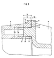
- Figure 2 shows a section of two housing parts at their interface in detail.
- Figure 3 shows a curing and shipping carton for glued loudspeaker housing.
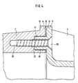
- Figure 4 shows a further section of two housing parts at their interface in detail.
- FIG. 1 shows a loudspeaker receptacle housing 5 which has two housing parts 6, 7 and in which a loudspeaker 8 is inserted.
- the mutually facing ends 9, 10 of the housing parts 6, 7 are designed as flanges 11, 12.
- An adhesive bead 15 is arranged between the flange surfaces 13, 14 formed by the flanges 11, 14, which glues the two housing parts 6, 7 to one another throughout.
- the plastic bead 15 is formed from a Sika PUR adhesive with the manufacturer's name SikaTack®-Instant and has a hardness of 50 Shore A and an elongation at break of 600%.
- the thickness (D K ) of the adhesive bead 15 between the flange surfaces 13, 14 is 0.5 mm in the exemplary embodiment shown.
- Holding clips 16 are pushed onto the flanges 11, 12 in the direction of the arrow during the curing time of the adhesive bead 15.
- the center piece 17 of such a holding clip 16, the width (B) of which corresponds to the thickness (D K ) of the adhesive bead 15, is immersed in the gap 18 between the flange surfaces 13, 14 which is free of adhesive, while the resilient clip ends 19 the flanges 11 , 12 press against the center piece 17.
- the flange 12 has a blind hole 20 on its flange surface 14, into which a spacer 21 arranged on the flange surface 13 of the flange 11 engages and hits the bottom 22 of the blind hole 20.
- the overall length (B L ) of the spacer 21 corresponds to the depth (S T ) of the blind hole 20 plus the desired minimum adhesive thickness (D K ) of the plastic bead 15 which bonds the housing parts 6.7.
- the diameter (D S ) of the blind hole 20 exceeds the diameter ( D A ) of the spacer 21 is scarce.
- FIG. 3 illustrates a simple production example for realizing a glued loudspeaker receptacle housing 5.
- a two-part curing and transport box 23 made of molded plastic is used.
- the lower part 24 of the curing and transport box 23 has a receiving recess 25 into which the housing part 6 is inserted.
- the flange 11 of the housing part 6 then lies on the head side 26 of the lower part 24.
- the flange surface 13 is then provided with an adhesive bead 15.
- a housing part 7, already equipped with a loudspeaker 5, with the flange surface 14 is placed on the plastic bead 15.
- the spacers 21 and blind holes 20 located on the flange surfaces 13, 14 and described above in FIG.
- the upper part 27 of the receiving and transport box 23, which also contains a receiving recess 28, is then placed over the part of the loudspeaker receiving housing 5 protruding from the lower part 24.
- the upper part 27 Since the depth (T O ) of the receiving recess 28 of the upper part 27 is just below the height (H A ) of the part of the loudspeaker receiving housing 5 protruding from the lower part 24, the upper part 27 is pressed onto the lower part 24 by the force (P) along the direction of the arrow, so that the spacers 21 are placed on the bottom 22 of the blind hole 20.
- the force (P) required until the adhesive has hardened can be replaced by wrapping the upper part 27 and the lower part 24 of the receiving and transport carton 23 perpendicularly to their mutually facing edges with an adhesive strip (not shown) during a brief force (P) will.
- FIG. 4 shows another interface between two housing parts 6, 7 in Shown in detail, in deviation from FIG. 2, a self-tapping screw 29 is only guided through the flange 11 and the spacer 21 into a further blind hole 30 located at the bottom 22 of the blind hole 20.
- the force exerted by the screw 29 causes the two flange surfaces 13, 14 to be pressed against one another at least during the curing time of the adhesive.
- the screws 29 can be removed or can also remain in the flanges 11, 12, since it has been shown in comparison to removed screws 29 that up to a maximum of 4 screws 29 at the seams of two housing parts 6, 7 do not impair the auditory impression of the loudspeaker box .
- flange surfaces 13, 14 in each of the exemplary embodiments discussed above can be pretreated with a primer for better adhesion of the adhesive bead 15.
Landscapes
- Physics & Mathematics (AREA)
- Engineering & Computer Science (AREA)
- Acoustics & Sound (AREA)
- Signal Processing (AREA)
- Details Of Audible-Bandwidth Transducers (AREA)
Description
- Die Erfindung betrifft ein mehrteiliges - insbesondere zweiteiliges - Gehäuse zur Aufnahme von Lautsprechern. Ein solches Gehäuse ist zum Beispiel aus der EP-A-0 021 455 bekannt.
- Seit geraumer Zeit besteht in der Lautsprechertechnik das Problem, mehrteilige Lautsprechergehäuse so miteinander zu verbinden, daß das Lautsprechergehäuse trotz der Mehrteiligkeit keinen oder nur einen vernachlässigungsfähigen Einfluß auf das Wiedergabeverhalten des Lautsprechers ausübt. Derartig nachteilige Eigenschaften mehrteiliger Lautsprechergehäuse rühren daher, daß die Gehäuseteile im statischen Zustand lokale Verspannungen aufweisen, die im dynamischen Zustand den Höreindruck der Lautsprecherbox beeinträchtigen. Diese Verspannungen haben ihre Ursache darin, daß die Gehäuseteile an ihren einander zugewandten Kanten nach wirtschaftlicher Betrachtungsweise unvermeidbare Fertigungstoleranzen aufweisen, zu deren Überwindung und Erzielung einer durchgängig planen Verbindung der Gehäuseteile an ihren einander zugewandten Kanten eine Vielzahl von Schrauben oder Schnappen als mechanisch wirkende Verbindungselement eingesetzt werden. Aus diesem Grunde wird bei der Fertigung hochwertiger Lautsprecheraufnahmegehäuse vor dem mechanischen Verbinden zwischen den einander zugewandten Kanten der Gehäuseteile eine elastische Gummidichtung angeordnet. Diese Maßnahme bewirkt, daß wegen der die Fertigungstoleranzen ausgleichenden Wirkung der Gummidichtung die Kraftwirkungen der mechanischen Verbindungselemente zur Erzeugung einer durchgängigen und dichten Verbindung der Gehäuseteile geringer ausfallen. Hierdurch werden auch die Verspannungen der Gehäuseteile reduziert und der Höreindruck der Lautsprecherbox verbessert.
Der Erfindung liegt die Aufgabe zugrunde, ein mehrteiliges Lautsprecheraufnahmegehäuse zu schaffen, dessen Klangverhalten noch weiter verbessert ist. - Die Aufgabe wird dadurch gelöst, daß die das Lautsprecheraufnahmegehäuse bildenden Gehäuseteile schwimmend miteinander verklebt sind, indem ein Klebstoff mit einer Mindestschichtdicke von 0,5 mm, einer Härte von maximal 60 Shore A und einer Mindestbruchdehnung von 400 % die Gehäuse teile an ihren einander zugewandten Kanten durchgängig verklebt. Hierdurch wird sichergestellt, daß Fertigungstoleranzen an den Gehäusekanten ausgeglichen werden und überdies die so verfügten Gehäuseteile völlig verspannungsfrei aufeinanderstehen.
- Als besonders vorteilhaft erweist sich nach der Erfindung der Umstand, daß auf ein aufwendiges mechanisches Verbinden der Gehäuseteile verzichtet werden kann und eine Lagerhaltung für elastische Gummidichtungen gänzlich entfällt.
- Eine vorteilhafte Weiterbildung der Erfindung ist in Anspruch 2 ausgeführt. Durch die Anordnung von Fixierhilfen an den einander zugewandten Kanten der Gehäuseteile wird nicht nur ein einfaches Zusammensetzen der Gehäuseteile und eine Verhinderung von Radialverschiebungen der Gehäuseteile während des Durchhärtens des Klebstoffes sichergestellt, sondern auch durch die Baulänge der Fixierhilfen die jeweils gewünschte Mindestklebstoffdicke zwischen den Gehäuseteilen gewährleistet.
- Anspruch 3 gibt ein Verfahren zur Herstellung eines geklebten Lautsprecheraufnahmegehäuses an. Durch den Auftrag des Klebers mit einer die jeweils gewünschte Mindestklebstoffdicke zwischen den Gehäuseteilen im Endzustand übersteigenden Schichtdicke und durch das Aufeinanderpressen der Gehäuseteile zumindest während der Durchhärtzeit des Klebers wird erreicht, daß sich der Klebstoff zwischen den Gehäuseteilen besonders gut verteilt und nahezu die gesamte Breite der Kanten der Gehäuseteile als Klebefläche ausnutzt.
- Figur 1 zeigt eine Schnittdarstellung eines zweiteiligen Lautsprecheraufnahmegehäuses mit eingesetztem Lautsprecher.
- Figur 2 zeigt einen Schnitt zweier Gehäuseteile an ihrer Nahtstelle im Detail.
- Figur 3 zeigt einen Aushärte- und Transportkarton für geklebte Lautsprecheraufnahmegehäuse.
- Figur 4 zeigt einen weiteren Schnitt zweier Gehäuseteile an ihrer Nahtstelle im Detail.
- In Figur 1 ist ein Lautsprecheraufnahmegehäuse 5 dargestellt, welches zwei Gehäuseteile 6,7 aufweist und in welches ein Lautsprecher 8 eingesetzt ist. Die einander zugewandten Enden 9,10 der Gehäuseteile 6,7 sind als Flansche 11,12 ausgebildet. Zwischen den von den Flanschen 11,12 gebildeten Flanschflächen 13,14 ist eine Klebstoffwulst 15 angeordnet, welche die beiden Gehäuseteile 6,7 durchgängig miteinander verklebt. Die Kunststoffwulst 15 ist aus einem PUR-Klebstoff der Firma Sika mit der Herstellerbezeichnung SikaTack®-Instant gebildet und weist eine Härte von 50 Shore A und eine Bruchdehnung von 600 % auf. Die Dicke (DK) der Klebstoffwulst 15 zwischen den Flanschflächen 13,14 beträgt im dargestellten Ausführungsbeispiel 0,5 mm. Halteklammern 16 sind während der Durchhärtezeit der Klebstoffwulst 15 längs der Pfeilrichtung auf die Flansche 11,12 aufgeschoben. Das Mittelstück 17 einer derartigen Halteklammer 16, dessen Breite (B) der Dicke (DK) der Klebstoffwulst 15 entspricht, taucht dabei in den vom Klebstoff freien Spalt 18 zwischen den Flanschflächen 13,14 ein, während die federnd ausgebildeten Klammerenden 19 die Flansche 11,12 gegen das Mittelstück 17 drücken.
- In Figur 2 ist eine Nahtstelle zweier Gehäuseteile 6,7 im Detail dargestellt. In Abweichung zu Figur 1 weist der Flansch 12 an seiner Flanschfläche 14 ein Sackloch 20 auf, in welches ein an der Flanschfläche 13 des Flansches 11 angeordneter Abstandshalter 21 eingreift und auf dem Boden 22 des Sacklochs 20 aufstößt. Die Baulänge (BL) des Abstandshalters 21 entspricht der Tiefe (ST) des Sackloches 20 plus der gewünschten Mindestklebstoffdicke (DK) der die Gehäuseteile 6,7 verklebenden Kunststoffwulst 15. Der Durchmesser (DS) des Sackloches 20 übersteigt den Durchmesser (DA) des Abstandshalters 21 knapp.
- In Figur 3 ist ein einfaches Herstellungsbeispiel zur Realisierung eines geklebten Lautsprecheraufnahmegehäuses 5 veranschaulicht. Dazu wird ein zweiteiliger Aushärte- und Transportkarton 23 aus Formkunststoff verwendet. Das Unterteil 24 des Aushärte- und Transportkartons 23 weist eine Aufnahmevertiefung 25 auf, in die das Gehäuseteil 6 eingesetzt wird. Der Flansch 11 des Gehäuseteils 6 liegt hiernach auf der Kopfseite 26 des Unterteils 24 auf. Sodann wird die Flanschfläche 13 mit einer Klebstoffwulst 15 versehen. Im nächsten Arbeitsschritt wird ein bereits mit einem Lautsprecher 5 bestücktes Gehäuseteil 7 mit der Flanschfläche 14 auf die Kunststoffwulst 15 aufgesetzt. Die an den Flanschflächen 13,14 befindlichen und oben in Figur 2 beschriebenen Abstandshalter 21 und Sacklöcher 20 gewährleisten dabei ein genaues Zentrieren der Gehäuseteile 6,7 aufeinander und stellen sicher, daß die Klebstoffwulst 15 nicht etwa durch das Gewicht des Gehäuseteils 7 und des eingesetzten Lautsprechers 8 unter die gewünschte Mindestklebstoffdicke zusammengedrückt wird. Das Oberteil 27 des Aufnahme- und Transportkartons 23, welches ebenfalls eine Aufnahmevertiefung 28 enthält, wird sodann über das aus dem Unterteil 24 herausragende Teil des Lautsprecheraufnahmegehäuses 5 gestülpt. Da die Tiefe (TO) der Aufnahmevertiefung 28 des Oberteils 27 die Höhe (HA) des aus dem Unterteil 24 herausragenden Teils des Lautsprecheraufnahmegehäuses 5 knapp unterschreitet, wird durch Krafteinwirkung (P) längs der Pfeilrichtung das Oberteil 27 auf das Unterteil 24 gedrückt, so daß die Abstandshalter 21 auf dem Boden 22 des Sackloches 20 aufsetzen. Die bis zur Durchhärtung des Klebstoffs erforderliche Krafteinwirkung (P) läßt sich dadurch ersetzen, daß das Oberteil 27 und das Unterteil 24 des Aufnahme- und Transportkartons 23 während einer nur kurzzeitigen Krafteinwirkung (P) senkrecht zu ihren einander zugewandten Kanten mit einem nicht dargestellten Klebestreifen umwickelt werden.
- In Figur 4 ist eine weitere Nahtstelle zweier Gehäuseteile 6,7 im Detail dargestellt, wobei in Abweichung zu Figur 2 lediglich durch den Flansch 11 und den Abstandshalter 21 eine selbstschneidende Schraube 29 in ein am Boden 22 des Sacklochs 20 befindliches weiteres Sackloch 30 geführt ist. Die von der Schraube 29 ausgeübte Kraft bewirkt, daß die beiden Flanschflächen 13,14 zumindest während der Durchhärtzeit des Klebstoffs aufeinander gepreßt werden. Hiernach können die Schrauben 29 entfernt werden oder aber auch in den Flanschen 11,12 verbleiben, da sich im Vergleich zu entfernten Schrauben 29 gezeigt hat, daß bis zu maximal 4 Schrauben 29 an den Nahtstellen zweier Gehäuseteile 6,7 den Höreindruck der Lautsprecherbox nicht beeinträchtigen.
- Es wird darauf hingewiesen, daß die Flanschflächen 13,14 in jedem vorstehend behandelten Ausführungsbeispiel zur besseren Haftung der Klebstoffwulst 15 mit einem Primer vorbehandelt sein können.
Claims (3)
- Mehrteiliges - insbesondere zweiteiliges - Gehäuse zur Aufnahme von Lautsprechern,
dadurch gekennzeichnet,- daß die die Lautsprecheraufnahme bildenden Gehäuseteile (6,7) schwimmend miteinander verklebt sind, und- daß der die Gehäuseteile (6,7) an ihren einander zugewandten Kanten (11,12) durchgängig verklebende Klebstoff eine Mindestschichtdicke (DK) von 0,5 mm aufweist und eine Härte von maximal 60 Shore A sowie eine Mindestbruchdehnung von 400 % aufweist. - Lautsprecheraufnahmegehäuse nach Anspruch 1,
dadurch gekennzeichnet,
daß die Gehäuseteile (6,7) an ihren einander zugewandten Kanten (11,12) Fixierhilfen (16;21) aufweisen, die ein einfaches Zusammensetzen der Gehäuseteile (6,7) ermöglichen, bis zum Durchhärten des Klebstoffes ein gegenseitiges radiales Verschieben der Gehäuseteile (6,7) unterbinden und durch ihre Baulänge die jeweils gewünschte Mindestklebstoffdicke (DK) zwischen den Gehäuseteilen (6,7) gewährleisten. - Verfahren zur Herstellung eines Lautsprecheraufnahmegehäuses nach Anspruch 1,
dadurch gekennzeichnet,- daß die Gehäuseteile (6,7) schwimmend und durchgehend an ihren einander zugewandken Kanten (11,12) mittels eines, nach Durchhärtung, eine Härte von maximal 60 Shore A sowie eine Mindestbruchdehnung von 400% aufweisenden Klebstoffs verklebt werden, wobei der Klebstoff mit einer Schichtdicke aufgetragen wird, welche eine jeweils gewünschte, mindestens 0,5 mm betragende Mindestschichtdicke zwischen den Gehäuseteilen (6,7) im Endzustand übersteigt und- daß die jeweils verklebten Gehäuseteile (6,7) zumindest während der Durchhärtzeit des Klebstoffs gegeneinander gepreßt werden.
Applications Claiming Priority (2)
| Application Number | Priority Date | Filing Date | Title |
|---|---|---|---|
| DE3941734A DE3941734A1 (de) | 1989-12-18 | 1989-12-18 | Lautsprecheraufnahmegehaeuse |
| DE3941734 | 1989-12-18 |
Publications (3)
| Publication Number | Publication Date |
|---|---|
| EP0433704A2 EP0433704A2 (de) | 1991-06-26 |
| EP0433704A3 EP0433704A3 (en) | 1992-04-01 |
| EP0433704B1 true EP0433704B1 (de) | 1994-06-08 |
Family
ID=6395692
Family Applications (1)
| Application Number | Title | Priority Date | Filing Date |
|---|---|---|---|
| EP90122510A Expired - Lifetime EP0433704B1 (de) | 1989-12-18 | 1990-11-26 | Lautsprecheraufnahmegehäuse |
Country Status (2)
| Country | Link |
|---|---|
| EP (1) | EP0433704B1 (de) |
| DE (2) | DE3941734A1 (de) |
Families Citing this family (2)
| Publication number | Priority date | Publication date | Assignee | Title |
|---|---|---|---|---|
| DE19815751C2 (de) * | 1998-04-08 | 2000-10-26 | Matthias Petig | Lautsprecher mit einem aus mehreren Bauteilen gebildeten Lautsprechergehäuse |
| DE10330453A1 (de) * | 2003-07-05 | 2005-01-27 | Karosseriewerk Krämer GmbH | Schalldämmender Wandaufbau |
Family Cites Families (3)
| Publication number | Priority date | Publication date | Assignee | Title |
|---|---|---|---|---|
| DE2260983A1 (de) * | 1972-12-13 | 1974-06-20 | Geb Otten Marita Preuss | Lautsprecherbox |
| DE2922998A1 (de) * | 1979-06-07 | 1980-12-18 | Braun Ag | Lautsprechergehaeuse |
| DE8303355U1 (de) * | 1983-02-08 | 1983-06-16 | Hornaff, Bernd, 6900 Heidelberg | Lautsprechergehaeuse |
-
1989
- 1989-12-18 DE DE3941734A patent/DE3941734A1/de not_active Withdrawn
-
1990
- 1990-11-26 EP EP90122510A patent/EP0433704B1/de not_active Expired - Lifetime
- 1990-11-26 DE DE59006041T patent/DE59006041D1/de not_active Expired - Fee Related
Also Published As
| Publication number | Publication date |
|---|---|
| DE3941734A1 (de) | 1991-06-20 |
| DE59006041D1 (de) | 1994-07-14 |
| EP0433704A3 (en) | 1992-04-01 |
| EP0433704A2 (de) | 1991-06-26 |
Similar Documents
| Publication | Publication Date | Title |
|---|---|---|
| EP0742762B1 (de) | Verfahren für die herstellung und den einbau einer glasscheibe mit rahmen, insbesondere an einem fahrzeugteil | |
| EP0615875B1 (de) | Verfahren zur Herstellung eines starren Deckels für ein Fahrzeugdach und nach dem Verfahren hergestellter Deckel | |
| DE8807929U1 (de) | Verbindungsvorrichtung | |
| DE2937926A1 (de) | Membran fuer elektroakustische wandler | |
| DE1939189A1 (de) | Wickelkoerper mit Befestigungselement zum Befestigen eines Folienbandes od.dgl. | |
| DE19626813C2 (de) | Verfahren zur Herstellung einer Sicke für eine Lautsprechermembran | |
| EP1078551A1 (de) | Plattenlautsprecher | |
| DE2122488C3 (de) | Verfahren zum Herstellen einer Akustikplatte und danach hergestellte Akustikplatte | |
| EP0433704A2 (de) | Lautsprecheraufnahmegehäuse | |
| DE2755265C3 (de) | Abdichtungsstreifen bestehend aus einem Bürstenstreifen und einem diesen C-förmig umfassenden Haltestreifen | |
| EP0971814B2 (de) | Verfahren zur herstellung einer verbindung eines dichtungsbauteils mit einem bauelement | |
| DE3886157T2 (de) | Verfahren zur Herstellung einer Platte. | |
| EP3728501A1 (de) | Verfahren zur herstellung von klebflächen mittels einer 3d-druckvorrichtung | |
| DE4306369C2 (de) | Dichtungspackung für Stopfbuchsen an Armaturen und Apparaten | |
| DE69701291T2 (de) | Piezoelektrischer betätiger-wandler für tonwiedergabe-systeme | |
| DE1116422B (de) | Verfahren zur Herstellung von endlosen Magnettonbaendern | |
| EP0276433B1 (de) | Verfahren zur Herstellung einer eine Abtropfkante aufweisenden Arbeitsplatte | |
| EP0392407A2 (de) | Schallschluckender Körper | |
| DE102019108526A1 (de) | T-Verbinder, insbesondere Sprossenverbinder, für geklebte Verglasungen | |
| DE1944833A1 (de) | Verfahren zur Herstellung von Moebelplatten | |
| DE3020559C2 (de) | Verfahren zur Herstellung von maß- und oberflächengetreuen Abgüssen von Plastiken sowie Vorrichtung zur Durchführung des Verfahrens | |
| DE1472022C3 (de) | ||
| DE2028451A1 (de) | Winkelstück zur Befestigung von Hohlprofil-Ecken | |
| EP0135663A2 (de) | Abdeckplane | |
| DE1190508B (de) | Verfahren zur Herstellung eines Magnetkopfes zur Aufzeichnung oder Wiedergabe von Signalen |
Legal Events
| Date | Code | Title | Description |
|---|---|---|---|
| PUAI | Public reference made under article 153(3) epc to a published international application that has entered the european phase |
Free format text: ORIGINAL CODE: 0009012 |
|
| AK | Designated contracting states |
Kind code of ref document: A2 Designated state(s): BE DE FR GB IT SE |
|
| PUAL | Search report despatched |
Free format text: ORIGINAL CODE: 0009013 |
|
| RAP1 | Party data changed (applicant data changed or rights of an application transferred) |
Owner name: NOKIA (DEUTSCHLAND) GMBH |
|
| AK | Designated contracting states |
Kind code of ref document: A3 Designated state(s): BE DE FR GB IT SE |
|
| 17P | Request for examination filed |
Effective date: 19920513 |
|
| 17Q | First examination report despatched |
Effective date: 19931027 |
|
| GRAA | (expected) grant |
Free format text: ORIGINAL CODE: 0009210 |
|
| AK | Designated contracting states |
Kind code of ref document: B1 Designated state(s): BE DE FR GB IT SE |
|
| GBT | Gb: translation of ep patent filed (gb section 77(6)(a)/1977) |
Effective date: 19940614 |
|
| REF | Corresponds to: |
Ref document number: 59006041 Country of ref document: DE Date of ref document: 19940714 |
|
| ITF | It: translation for a ep patent filed | ||
| ET | Fr: translation filed | ||
| EAL | Se: european patent in force in sweden |
Ref document number: 90122510.2 |
|
| PLBE | No opposition filed within time limit |
Free format text: ORIGINAL CODE: 0009261 |
|
| STAA | Information on the status of an ep patent application or granted ep patent |
Free format text: STATUS: NO OPPOSITION FILED WITHIN TIME LIMIT |
|
| 26N | No opposition filed | ||
| PGFP | Annual fee paid to national office [announced via postgrant information from national office to epo] |
Ref country code: FR Payment date: 19951109 Year of fee payment: 6 |
|
| PGFP | Annual fee paid to national office [announced via postgrant information from national office to epo] |
Ref country code: SE Payment date: 19951116 Year of fee payment: 6 |
|
| PGFP | Annual fee paid to national office [announced via postgrant information from national office to epo] |
Ref country code: GB Payment date: 19951117 Year of fee payment: 6 |
|
| PGFP | Annual fee paid to national office [announced via postgrant information from national office to epo] |
Ref country code: BE Payment date: 19960109 Year of fee payment: 6 |
|
| PGFP | Annual fee paid to national office [announced via postgrant information from national office to epo] |
Ref country code: DE Payment date: 19960115 Year of fee payment: 6 |
|
| PG25 | Lapsed in a contracting state [announced via postgrant information from national office to epo] |
Ref country code: GB Effective date: 19961126 |
|
| PG25 | Lapsed in a contracting state [announced via postgrant information from national office to epo] |
Ref country code: SE Effective date: 19961127 |
|
| PG25 | Lapsed in a contracting state [announced via postgrant information from national office to epo] |
Ref country code: BE Effective date: 19961130 |
|
| BERE | Be: lapsed |
Owner name: NOKIA (DEUTSCHLAND) G.M.B.H. Effective date: 19961130 |
|
| GBPC | Gb: european patent ceased through non-payment of renewal fee |
Effective date: 19961126 |
|
| PG25 | Lapsed in a contracting state [announced via postgrant information from national office to epo] |
Ref country code: FR Effective date: 19970731 |
|
| PG25 | Lapsed in a contracting state [announced via postgrant information from national office to epo] |
Ref country code: DE Effective date: 19970801 |
|
| EUG | Se: european patent has lapsed |
Ref document number: 90122510.2 |
|
| REG | Reference to a national code |
Ref country code: FR Ref legal event code: ST |
|
| PG25 | Lapsed in a contracting state [announced via postgrant information from national office to epo] |
Ref country code: IT Free format text: LAPSE BECAUSE OF NON-PAYMENT OF DUE FEES;WARNING: LAPSES OF ITALIAN PATENTS WITH EFFECTIVE DATE BEFORE 2007 MAY HAVE OCCURRED AT ANY TIME BEFORE 2007. THE CORRECT EFFECTIVE DATE MAY BE DIFFERENT FROM THE ONE RECORDED. Effective date: 20051126 |