EP0433656A1 - Façade de bâtiment fixée sur une structure porteuse - Google Patents
Façade de bâtiment fixée sur une structure porteuse Download PDFInfo
- Publication number
- EP0433656A1 EP0433656A1 EP90121841A EP90121841A EP0433656A1 EP 0433656 A1 EP0433656 A1 EP 0433656A1 EP 90121841 A EP90121841 A EP 90121841A EP 90121841 A EP90121841 A EP 90121841A EP 0433656 A1 EP0433656 A1 EP 0433656A1
- Authority
- EP
- European Patent Office
- Prior art keywords
- facade
- support
- plate
- building
- plates
- Prior art date
- Legal status (The legal status is an assumption and is not a legal conclusion. Google has not performed a legal analysis and makes no representation as to the accuracy of the status listed.)
- Withdrawn
Links
Images


Classifications
-
- E—FIXED CONSTRUCTIONS
- E04—BUILDING
- E04F—FINISHING WORK ON BUILDINGS, e.g. STAIRS, FLOORS
- E04F13/00—Coverings or linings, e.g. for walls or ceilings
- E04F13/07—Coverings or linings, e.g. for walls or ceilings composed of covering or lining elements; Sub-structures therefor; Fastening means therefor
- E04F13/08—Coverings or linings, e.g. for walls or ceilings composed of covering or lining elements; Sub-structures therefor; Fastening means therefor composed of a plurality of similar covering or lining elements
- E04F13/0801—Separate fastening elements
- E04F13/0832—Separate fastening elements without load-supporting elongated furring elements between wall and covering elements
- E04F13/0853—Separate fastening elements without load-supporting elongated furring elements between wall and covering elements adjustable perpendicular to the wall
- E04F13/0855—Separate fastening elements without load-supporting elongated furring elements between wall and covering elements adjustable perpendicular to the wall adjustable in several directions, one of which is perpendicular to the wall
Definitions
- the present invention relates to a building facade fastened to a supporting structure with a plurality of facade panels connected to the supporting structure indirectly via supporting anchors, in particular made of natural stone, with individual facade panels optionally being arranged removably from the building facade, a supporting anchor for holding facade panels to a supporting structure, preferably on Building facades, facade panels, preferably for building facades, and a securing element for securing facade panels, preferably for building facades.
- Anchoring systems for natural stone facades are known, so-called quick-assembly anchor systems, with the aid of which external facades, in particular natural stone slabs, are attached to the supporting structure of buildings.
- the so-called quick-assembly anchors which are used in large numbers in various designs for such facade panels, serve to hold such panels in place.
- the insurance companies in particular made the condition, from time to time at least on a random basis remove individual facade panels and thus check the general condition of the assembly anchor systems.
- the individual facade panels are assembled from bottom to top in such a way that individual rows of facade panels or even individual facade panels cannot be lifted out of the facade at will, but the facade must be dismantled from above until the corresponding one Access to the back room to be checked is exposed behind the corresponding facade panel.
- the present invention aims to provide a mounting system for building facades, which does not have this disadvantage.
- a support anchor that makes this possible is characterized by the characterizing part of a claim.
- the invention also includes a facade panel, which is distinguished by the wording of a claim, while a securing element completes the invention and, according to one claim, serves to secure facade panels to building facades.
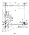
- Fig. 1 shows a section of a building facade 1 with facade panels 3, which here have a square or a rectangular or square shape.
- the corners are provided with recesses 4, which, as can be seen in FIG. 2, are of slot-like design.
- the facade panels 3 are fastened to a support structure 14 in such a way that horizontal spaces 5 and vertical spaces 6 result between their sides.
- the space between the facade panels 3 on the one hand and the support structure 14 on the other hand can be partially or completely filled with insulating material. However, it is also possible to leave this space as it is shown in FIG. 2.
- Sliding blocks 8 consist of a plate 9 and two retaining bolts 10 projecting laterally from their main surfaces. These sliding blocks 8 can preferably be made of plastic, optionally glass fiber reinforced. They serve as actual securing elements and are introduced into the facade in a manner explained later.
- the fastening system of the facade panels on the support structure 14 includes support anchor bolts 15 which are anchored in the support structure 14 in a known manner.
- the free end of the anchor bolts 15 is formed as a threaded end 16, which is the inclusion of a Mother 17 serves.
- the support anchor bolt 15 is provided for receiving a support anchor 18, with a vertical support anchor leg 19 and a horizontal support anchor leg 20, which are composed of two identical plates 21 and 22 which are spaced apart from one another.
- a U-shaped connector 23 is used to hold them together, which holds the two vertical legs of the plates 21 and 22 together, while a screw 24 with a spacer tube 25 ensures the necessary space between the two plates 21 and 22.
- the horizontal support arm leg 20 is provided with a sliding rail 27 which has a self-contained, horizontal slot 28 and has two horizontal, laterally projecting support bolts 29 at its free end.
- a screw 31 is used to hold the slide rail 27 in the desired, advanced position.
- the distance between the plates 21 and 22 is greater than the thickness of the slide rail 27.
- the play is achieved by inserting a washer 32 between the plates 21 and 22 and the rail 27, ie compensated for by sliding on the screw 31.
- the sliding rail 27 also rests at the free end of the support arm leg 20 on a support 34, which consists of a spacer sleeve 36, held by means of a screw 35.
- the entire anchoring system also includes a wedge plate 38 with an oblique slot 39, in which slot the support anchor bolt 15 rests.
- the plate 38 with the oblique slot 39 in the dash-dot line Layer 40 can be assembled. This doubles the height adjustment distance.
- the support arm leg 19 is provided at the rear with a recess 41, the depth of which is smaller than the thickness of the wedge plate 38.
- the support anchor bolts 15 are initially fastened in the support structure 14 at appropriate intervals, after which the support anchor 18 can be mounted and adjusted in height, side and distance with respect to the support structure 14 in the three directions and then fixed.
- the wedge plate 38 is initially pushed onto the support anchor bolt 15, the two plates 21 and 22 of the support anchor leg 19, as shown in FIG. 1, enclosing the support anchor bolt 15 laterally.
- the U-shaped connector 23 is then pushed onto the bolt 15 and held in place by means of the nut 17.
- the support anchor 18 is raised or lowered. 1 shows the lowest position of the support armature 18.
- the lateral adjustment takes place in the sense that the width of the sliding rail 27 is approximately 5 mm less than the inner distance of the two plates 21 and 22, which ensures an adjustment of ⁇ 5 mm lateral displacement of the support bolts 29 of the sliding rail 27.
- the distance between the facade panels 3 is carried out by correspondingly pulling out or pushing in the sliding rail 27 and securing it by means of the screw 31.
- the nut 17 is tightened so that the support arm leg 19 presses the wedge plate 38 onto the front surface of the support structure 14 and thus holds the support armature 18 in its vertical position. Tightening the screw 31 secures the extended position of the slide rail 27 and thus the desired distance and the alignment of the facade panels 3 with respect to the support structure 14.
- the facade panel 3 to be assembled is gripped and attached to the two support anchors 18 provided for this panel.
- the facade panel 3 is, at the top outwardly inclined, pushed onto the anchor in such a way that the groove-shaped recess 4 receives the support bolts 29 and, when the panel 3 is pushed back into its vertical position, the two support bolts 12 on the left and right onto the support bolts 29 two sliding rails 27 come to rest, as can be seen in FIG. 2.
- the upper slot nuts 8 are used for these plates in such a way that the retaining bolts 10 protrude into the vertical spaces 6, as is clear from FIG. 1 reveals.
- the plate 9 of the sliding block 8 projects into the corresponding slot-like recess 4, as a result of which the lower facade plate 3 is securely held.
- the facade panels 3 are assembled from the bottom up to the building facade 1.
- the two upper sliding blocks 8 can first be pushed to the left after lifting on the left and to the right on the right, with the retaining bolts 10 in the horizontal spaces 5 slide.
- the lower right sliding block 8 is shifted to the right in the same way and lastly the left sliding block 8, whereupon the plate 3 is tilted forward and thus the support bolt 12 slides off the support bolt 29.
- this plate 3 can be lifted diagonally upwards.
- the support bolts 29 are out of engagement with the recess 4, the plate 3 can be removed.
- the plates weigh approx. 50 to 70 kp.
- the facade panel 3 has thus been individually lifted out of the building facade 1, so that it is possible to check the parts lying behind it, the support anchor and the support structure, and in particular also the support anchor bolt 15.
- the facade panel 3 is then installed in the reverse order.
- Fig. 3 shows a section of a building facade 51 with facade panels 53, which here have a square or a rectangular or square shape. Their corners are each provided with a recess 54 which, as can be seen in FIG. 4, is of slot-like design.
- the facade panels 53 are fastened to a support structure 14 such that there are horizontal spaces 5 and vertical spaces between their sides 6 result.
- the space between the facade panels 53 on the one hand and the supporting structure 14 on the other hand can remain empty or can be partially or completely filled with insulating material.
- T-nuts 58 consist of a plate 59 with a reduced head part 60. These T-nuts 58 can preferably be made of plastic, optionally glass fiber reinforced. They serve as actual securing elements and are introduced into the facade in a manner explained later.
- the fastening system of the facade panels on the support structure 14 includes support anchor bolts 15, which are anchored in the support structure 14 in a known manner.
- the free end of the anchor bolts 15 is designed as a threaded end 16 which serves to receive a nut 17.
- the support anchor bolt 15 is provided for receiving a support anchor 68, with a horizontal support anchor leg 69 and a vertical support anchor leg 70, which are each composed of two identical plates 84 and 85 or 71 and 72 which are spaced apart from one another.
- a U-shaped connector 23 serves to hold them together, which holds the two plates 71 and 72 of the vertical leg together, while a screw 24 with a spacer tube 25 ensures the necessary space between the two plates 71 and 72.
- the horizontal support leg 69 is connected to the vertical support leg 70 by means of two screws 62 and 63.
- the leg 69 is provided with a sliding rail 77, which is one in itself has closed, horizontal slot 28.
- the sliding rail 77 is provided at its free end with a downwardly open slot 76, which enables the sliding block 58 to be pushed through. This creates an additional backup for the three remaining plates 53 when the fourth plate is lifted out.
- a holding piece 79 with teeth 78 is mounted in a slot 80 by means of a screw 35.
- the toothing 78 engages in a counter toothing of the rail 77.
- These toothings, together with the slot 80, allow the rail 77 to be fine-tuned.
- a screw 31 is also used to hold the sliding rail 77 in the desired, advanced position, on its side facing away from the screw head a washer is provided.
- the entire anchoring system also includes a wedge plate 88 with an oblique slot 39 through which slot the support anchor bolt 15 projects.
- the support arm leg 19 is provided at the rear with a recess 41, the depth of which is smaller than the thickness of the wedge plate 88.
- the support anchor bolts 15 are initially fastened in the support structure 14 at appropriate intervals, after which the support anchor 68 is mounted and in terms of height, side and distance with respect to the support structure 14 in the three directions can be adjusted and then fixed.
- the wedge plate 88 is initially pushed onto the support bolt 15, the two plates 71 and 72 of the support arm 70, as shown in FIG. 3, to laterally surround the support bolt 15.
- the U-shaped connector 23 is then pushed onto the bolt 15 and held in place by means of the nut 17.
- the support anchor 68 is raised or lowered. 3 shows the lowest position of the support anchor 68.
- the spacing of the facade panels 53 from the support structure 14 is carried out by correspondingly pulling out or pushing in the slide rail 77, the fine adjustment thereof with the aid of the holding piece 79 and the securing thereof by means of the screw 31.
- the nut 17 is tightened so that the support arm leg 70 presses the wedge plate 88 onto the front surface of the support structure 14 and thus fixes the support armature 68 in its vertical position. Tightening the screw 31 secures the pull-out position of the slide rail 27 and thus the desired distance and the alignment of the facade panels 53 with respect to the support structure 14.
- the facade panel 53 to be assembled is gripped and attached to the two support anchors 68 provided for this panel.
- the facade panel 53 is slanted upwards outwards (FIG. 4) onto the anchor in such a way that the groove-shaped recess 54 receives the support bolts 29 and the panel 53 is pushed back into its vertical position. with the groove bottom of the recess 54 rests on the bolt 29, as can be seen in FIG. 4.
- the upper slot nuts 58 for these plates 53 are inserted into the plates 53 below, as shown in FIGS. 3 and 4, against the inner end of the recess 54.
- the sliding block 58 is pushed against the sliding rail 77 and through the slot 76 until the sliding block 58 is in its central securing position (FIG. 3). It then, m.W., protrudes the plate 59 of the sliding block 58 into the corresponding slot-like recess 54 of the upper plate 53 and the slot 76 of the sliding rail 77. This secures the lower facade plate 53 securely.
- the facade panels 53 are assembled from the bottom up to the building facade 51.
- the four sliding blocks 58 can be pushed to the left and to the right on the right, for example with a hook-shaped tool, whereby they are in the groove bases of the recesses slide.
- the two upper sliding blocks have to be shifted by half the length of the plate 59, the lower by half the length of the head part in order to release the plate 53 to be swung out and then lifted out.
- the surrounding plates 53 keep theirs vertical position. This is ensured by the connection between the sliding block 58 and its part lying in the slot 76 of the sliding rail 77. A buckling or buckling of the remaining wall plates 53 is therefore impossible even with large air forces - they are prevented by the connection of sliding block 58 and sliding rail 77 via slot 76.
- the facade panel 53 has thus been individually lifted out of the building facade 1, so that it is possible to check the parts behind it, the support anchor 68 and the support structure 14, and in particular also the support anchor bolt 15.
- the facade plate 53 is then assembled in the reverse order.
Landscapes
- Engineering & Computer Science (AREA)
- Architecture (AREA)
- Civil Engineering (AREA)
- Structural Engineering (AREA)
- Finishing Walls (AREA)
Applications Claiming Priority (2)
| Application Number | Priority Date | Filing Date | Title |
|---|---|---|---|
| CH4617/89 | 1989-12-22 | ||
| CH461789 | 1989-12-22 |
Publications (1)
| Publication Number | Publication Date |
|---|---|
| EP0433656A1 true EP0433656A1 (fr) | 1991-06-26 |
Family
ID=4279455
Family Applications (1)
| Application Number | Title | Priority Date | Filing Date |
|---|---|---|---|
| EP90121841A Withdrawn EP0433656A1 (fr) | 1989-12-22 | 1990-11-15 | Façade de bâtiment fixée sur une structure porteuse |
Country Status (1)
| Country | Link |
|---|---|
| EP (1) | EP0433656A1 (fr) |
Cited By (5)
| Publication number | Priority date | Publication date | Assignee | Title |
|---|---|---|---|---|
| EP0566829A1 (fr) * | 1992-04-22 | 1993-10-27 | HALFEN GmbH & CO. Kommanditgesellschaft | Console d'appui pour blocs de construction, plaques de parement ou similaires |
| EP0869232A1 (fr) * | 1997-04-01 | 1998-10-07 | Hakron Verankeringstechniek B.V. | Dispositif de console |
| NL1005692C2 (nl) * | 1997-04-01 | 1998-10-12 | Hakron Verankeringstechniek B | Consolesamenstel. |
| WO2010023031A1 (fr) * | 2008-08-26 | 2010-03-04 | Mecanismos, Anclajes Y Sistemas Autoportantes, S. L. | Dispositif de support pour dalles de couverture |
| DE202014003376U1 (de) | 2014-04-23 | 2014-04-30 | Halfen Gmbh | Konsolanker |
Citations (5)
| Publication number | Priority date | Publication date | Assignee | Title |
|---|---|---|---|---|
| DE2611635A1 (de) * | 1976-03-19 | 1977-09-22 | Berger Geb Braeunig Hildegard | Tragfaehige verankerung fuer fassadenplatten und verfahren zur verankerung von fassadenplatten |
| FR2381932A2 (fr) * | 1977-02-25 | 1978-09-22 | Serero Ets Reboud Et Rouleau | Dispositif de fixation pour revetement en particulier pour revetement en pierre de taille |
| EP0091858A1 (fr) * | 1982-04-08 | 1983-10-19 | Societe De Construction Industrielle Du Batiment - Socib | Revêtement isolant extérieur destiné à des murs ou parois de bâtiments |
| EP0164335A2 (fr) * | 1984-06-08 | 1985-12-11 | Ferdinand Pointner | Ancre pour le revêtement en pierre de façades ou similaire |
| EP0245635A2 (fr) * | 1986-05-14 | 1987-11-19 | Unistrut Europe PLC | Dispositif de fixation pour panneaux |
-
1990
- 1990-11-15 EP EP90121841A patent/EP0433656A1/fr not_active Withdrawn
Patent Citations (5)
| Publication number | Priority date | Publication date | Assignee | Title |
|---|---|---|---|---|
| DE2611635A1 (de) * | 1976-03-19 | 1977-09-22 | Berger Geb Braeunig Hildegard | Tragfaehige verankerung fuer fassadenplatten und verfahren zur verankerung von fassadenplatten |
| FR2381932A2 (fr) * | 1977-02-25 | 1978-09-22 | Serero Ets Reboud Et Rouleau | Dispositif de fixation pour revetement en particulier pour revetement en pierre de taille |
| EP0091858A1 (fr) * | 1982-04-08 | 1983-10-19 | Societe De Construction Industrielle Du Batiment - Socib | Revêtement isolant extérieur destiné à des murs ou parois de bâtiments |
| EP0164335A2 (fr) * | 1984-06-08 | 1985-12-11 | Ferdinand Pointner | Ancre pour le revêtement en pierre de façades ou similaire |
| EP0245635A2 (fr) * | 1986-05-14 | 1987-11-19 | Unistrut Europe PLC | Dispositif de fixation pour panneaux |
Cited By (6)
| Publication number | Priority date | Publication date | Assignee | Title |
|---|---|---|---|---|
| EP0566829A1 (fr) * | 1992-04-22 | 1993-10-27 | HALFEN GmbH & CO. Kommanditgesellschaft | Console d'appui pour blocs de construction, plaques de parement ou similaires |
| EP0869232A1 (fr) * | 1997-04-01 | 1998-10-07 | Hakron Verankeringstechniek B.V. | Dispositif de console |
| NL1005692C2 (nl) * | 1997-04-01 | 1998-10-12 | Hakron Verankeringstechniek B | Consolesamenstel. |
| WO2010023031A1 (fr) * | 2008-08-26 | 2010-03-04 | Mecanismos, Anclajes Y Sistemas Autoportantes, S. L. | Dispositif de support pour dalles de couverture |
| DE202014003376U1 (de) | 2014-04-23 | 2014-04-30 | Halfen Gmbh | Konsolanker |
| EP2937492A1 (fr) | 2014-04-23 | 2015-10-28 | HALFEN GmbH | Console d'ancrage |
Similar Documents
| Publication | Publication Date | Title |
|---|---|---|
| DE3530694C2 (fr) | ||
| DE10056177B4 (de) | Befestigungsvorrichtung für plattenförmige Fassadenelemente | |
| EP0176973A2 (fr) | Fixation pour balises | |
| DE4342748A1 (de) | Befestigungssystem für Fassadenplatten | |
| DE3418146A1 (de) | Zerlegbare kioskkonstruktion, insbesondere fuer temporaere ausstellungen | |
| DE10307866B4 (de) | Glasfassade aus rahmenlos verlegten Glastafeln | |
| EP0433656A1 (fr) | Façade de bâtiment fixée sur une structure porteuse | |
| DE29615968U1 (de) | Vorrichtung zum Verschalen von Beton | |
| DE9309284U1 (de) | Vorrichtung zur lösbaren Halterung plattenförmiger Elemente | |
| DE4204788C2 (de) | Kopflager | |
| EP0716198B1 (fr) | Dispositif de fixation pour plaques de façade | |
| EP0272658A2 (fr) | Armature de support pour revêtements de façade | |
| EP0360001B1 (fr) | Dispositif de fixation de plaques à un mur, notamment des plaques en céramique | |
| DE19635376C1 (de) | Hohlraumboden | |
| CH675003A5 (en) | Support for panels of hollow floor - has means to adjust height of panels above underfloor | |
| DE20010401U1 (de) | Halter zur Befestigung von Plattenmaterial, insbesondere von Glasscheiben an Standsäulen o.dgl. | |
| AT409510B (de) | Wand- und fassaden-system | |
| EP0607462B1 (fr) | Faux plancher surélevé | |
| DE2623803C3 (de) | Vorrichtung zum Verankern von Stahlbetonfertigteilen an einem Baukörper | |
| DE20315878U1 (de) | Adapter für eine Halterung zur Befestigung hinterlüfteter Fassadenelemente | |
| DE3500149A1 (de) | Vertikale stuetzelemente sowie horizontale tragelemente aufweisende vorrichtung | |
| AT403306B (de) | Anordnung zur zumindest vorübergehenden halterung des in gebrauchslage unteren randbereiches einer schalplatte, einer schaltafel, eines wandelementes oder dergleichen | |
| EP0274984B1 (fr) | Dispositif pour fixer de manière échangeable des panneaux ou similaires | |
| EP0666380B1 (fr) | Dispositif pour la fixation de poteaux de balcon | |
| DE3443269A1 (de) | Wandelement |
Legal Events
| Date | Code | Title | Description |
|---|---|---|---|
| PUAI | Public reference made under article 153(3) epc to a published international application that has entered the european phase |
Free format text: ORIGINAL CODE: 0009012 |
|
| AK | Designated contracting states |
Kind code of ref document: A1 Designated state(s): AT BE DE DK ES FR GB IT NL SE |
|
| STAA | Information on the status of an ep patent application or granted ep patent |
Free format text: STATUS: THE APPLICATION IS DEEMED TO BE WITHDRAWN |
|
| 18D | Application deemed to be withdrawn |
Effective date: 19911228 |