EP0433637A1 - Dispositif pour séparer des poussières d'un gaz - Google Patents
Dispositif pour séparer des poussières d'un gaz Download PDFInfo
- Publication number
- EP0433637A1 EP0433637A1 EP90121356A EP90121356A EP0433637A1 EP 0433637 A1 EP0433637 A1 EP 0433637A1 EP 90121356 A EP90121356 A EP 90121356A EP 90121356 A EP90121356 A EP 90121356A EP 0433637 A1 EP0433637 A1 EP 0433637A1
- Authority
- EP
- European Patent Office
- Prior art keywords
- clean gas
- gas
- housing
- clean
- collecting
- Prior art date
- Legal status (The legal status is an assumption and is not a legal conclusion. Google has not performed a legal analysis and makes no representation as to the accuracy of the status listed.)
- Granted
Links
Images


Classifications
-
- B—PERFORMING OPERATIONS; TRANSPORTING
- B01—PHYSICAL OR CHEMICAL PROCESSES OR APPARATUS IN GENERAL
- B01D—SEPARATION
- B01D46/00—Filters or filtering processes specially modified for separating dispersed particles from gases or vapours
- B01D46/24—Particle separators, e.g. dust precipitators, using rigid hollow filter bodies
- B01D46/2403—Particle separators, e.g. dust precipitators, using rigid hollow filter bodies characterised by the physical shape or structure of the filtering element
- B01D46/2407—Filter candles
-
- B—PERFORMING OPERATIONS; TRANSPORTING
- B01—PHYSICAL OR CHEMICAL PROCESSES OR APPARATUS IN GENERAL
- B01D—SEPARATION
- B01D46/00—Filters or filtering processes specially modified for separating dispersed particles from gases or vapours
- B01D46/0002—Casings; Housings; Frame constructions
- B01D46/0005—Mounting of filtering elements within casings, housings or frames
- B01D46/0009—Tray-like arrangements of filters in a vessel
-
- B—PERFORMING OPERATIONS; TRANSPORTING
- B01—PHYSICAL OR CHEMICAL PROCESSES OR APPARATUS IN GENERAL
- B01D—SEPARATION
- B01D46/00—Filters or filtering processes specially modified for separating dispersed particles from gases or vapours
- B01D46/42—Auxiliary equipment or operation thereof
- B01D46/48—Removing dust other than cleaning filters, e.g. by using collecting trays
-
- B—PERFORMING OPERATIONS; TRANSPORTING
- B01—PHYSICAL OR CHEMICAL PROCESSES OR APPARATUS IN GENERAL
- B01D—SEPARATION
- B01D2273/00—Operation of filters specially adapted for separating dispersed particles from gases or vapours
- B01D2273/20—High temperature filtration
Definitions
- the invention relates to a device for dedusting a gas stream, in particular a hot gas stream under increased pressure, according to the preamble of patent claim 1.
- Candles made of porous ceramic material have been developed for filtration at temperatures of 500 - 1200 ° C and above.
- the candles cannot be made in any length; the longest candles available today are around 1.50 m long.
- it is essential to arrange the filter cartridges one above the other on several levels.
- the invention is based on a device which has become known from EP-B1-0 129 053.
- the clean gas collection units arranged in a vertical cylindrical housing each consist of a circular, flat base plate and a narrow, ring-shaped jacket part and a conical roof. There is an annular gap between the casing part and the housing wall for the downward gas flow. Hanging filter elements are attached to the perforated base plate.
- the clean gas collection units are connected to a coaxial clean gas tube, which is either guided through the cover or through the bottom of the housing, which is designed as a dust funnel.
- vertical pipes are arranged in the vicinity of the housing wall, from which horizontal blowpipes emanate on each floor and are guided through the jacket parts of the clean gas collection units into the latter. Each blowpipe is assigned to a group of several filter elements and is provided with nozzles pointing downwards above the individual filter elements.
- the individual filter elements are essentially flowed in cross flow by the gas stream to be cleaned. After cleaning, the dust that has already separated, in particular the finer grain fraction, can be entrained again and reach the filter elements again. This means a shortening of the cleaning period and - due to the non-reversible accumulation of fine particles - a shortening of the service life of the filter elements.
- the dust falls on the conical roof of the next clean gas collection unit.
- the angle of inclination of the roof must be at least equal to the angle of friction, unless additional cleaning devices are available.
- the length of the filter elements decreases in the direction of the housing axis. This affects the total filter area that can be accommodated in a housing of a given size.
- the conical shape of the roof makes it difficult to clean the roof when using standing filter elements.
- the long, branched lines for the propellant gas which is under high pressure, lie in the space through which hot gas flows and are therefore exposed to a temperature at which even austenitic steels have only a low strength.
- the pressure surges and the reaction forces occurring at the deflection points can lead to the failure of the materials.
- the subject of DE-AS 17 57 635 is a filter device with a raw gas inlet in the upper part of the housing and with a single clean gas collecting unit, which is arranged in the lower part of the housing directly above a dust funnel. It consists of several parallel collecting ducts arranged in the manner of a grating with gaps, on the upper side of which filter bags are connected, which are suspended in the upper housing part.
- the individual collecting channels are led through the housing wall to the outside and open into a separate clean gas chamber.
- At the end of each collecting duct there is a nozzle extension into which a propellant nozzle protrudes. The ends of the collecting channels are connected to a foreign gas line.
- the raw gas flows in a vertical direction along the filter bags.
- the raw gas flow supports the falling movement of the detached dust.
- the dust falls through the spaces between the collecting channels into the dust funnel. A gas stream does not flow through these gaps.
- the device is obviously not intended for cleaning hot gas. This follows not only from the use of filter bags that are not suitable for high temperatures, but also from the arrangement of the collecting channels. The passage through the housing wall would lead to thermal stress that the material would not withstand. Finally, purging with extraneous gas would cause thermal shock each time, unless the extraneous gas was heated to the temperature of the gas to be cleaned.
- the invention has for its object to develop a device of the type specified in the preamble of claim 1 so that the gas to be cleaned flows parallel to the filter elements on all floors, that is to say in cocurrent to the dust produced during backwashing, and that the filter area to be accommodated in a housing of predetermined dimensions is enlarged.
- the arrangement of the collecting channels specified in claim 2 is structurally simple and enables a uniformly dense distribution of the filter elements over the cross section of the housing.
- the combination of features of claim 3 has particular advantages for cleaning the filter elements.
- the clean gas pipes each of which is assigned to a group of filter elements, are used within the housing for supplying the purge gas. This eliminates the need to arrange a line system for the propellant gas within the housing.
- the in the clean gas chamber LPG tubes that are introduced can be made short and straight. As a result, they are less at risk from the mechanical stresses that occur with each surge.
- the equipment of the LPG pipes with water cooling is simplified. Due to the ejector effect, a large part of the purge gas is removed from the clean gas chamber; this avoids thermal shock.
- the standing arrangement of the filter candles according to claim 6 has the advantage over the hanging arrangement that the holders on the collecting channels can be made simpler, so that they are less susceptible to caking and the like in hot operation.
- Figure 1 shows a vertical section through an embodiment
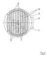
- Figure 2 shows a vertical section through the embodiment of Figure 1 in a section plane rotated by 90 °
- FIG. 4 shows detail A from FIG. 1 on an enlarged scale
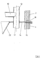
- FIG. 5 shows detail B from FIG. 1 on an enlarged scale
- Figure 6 shows a second embodiment of the invention.
- Figure 7 shows a third embodiment of the invention.
- FIGS. 1 to 5 has a two-part, upright, cylindrical housing 1, consisting of an upper part 2 with a domed lid 3 and a lower part 4 with an arched bottom 5. There is a flange connection 6 between the upper part 2 and the lower part 4.
- the lid 3 is provided with an inlet nozzle 7 for the raw gas.
- An outlet connection 8 for the clean gas is attached to the side of the lower part 4.
- two clean gas collection units 9 are housed one above the other on the floor. These each consist of a plurality of horizontal collecting channels 10, which are arranged in the manner of a grating parallel to one another on chords of the circular housing cross section, as can be seen from FIG. 3.
- the collecting channels 10 In cross section, the collecting channels 10 have the shape of a rectangle standing on its narrow side with an aspect ratio of approximately 1: 2.
- the filter candles 11 on the lower level extend approximately to the collecting channels 10 on the upper level, those on the upper level extend close to the cover 3.
- each collecting duct 10 The two ends of each collecting duct 10 are each connected to a clean gas pipe 12.
- the clean gas tubes 12 are arranged at a short distance from the cylindrical housing wall and form two mutually opposing groups.
- Each clean gas pipe 12 is connected to a collecting duct 10 both in the lower and in the upper floor.
- the clean gas pipe 12 has a recess at the connection point corresponding to the cross section of the collecting duct 10, so that the inside of the collecting duct 10 is in open communication with the inside of the clean gas pipe 12.
- each collecting channel 10 is interrupted in the middle by a partition 13, so that there is no continuous connection between the two clean gas pipes 12 connected at its ends.
- the clean gas pipes penetrate a horizontally arranged support ring 14, the outer edge strip of which rests on a support bearing 15 connected to the wall of the lower part 4 and is covered on its upper side by a seal 16 located in the insulation of the upper part.
- the clean gas pipes 12 welded to the support ring 14 each have a nozzle-like extension 17 below the support ring 14, the open, trumpet-like extended end (FIG. 5) of which extends into the vicinity of the base 5.
- Each clean gas tube 12 is assigned a significantly thinner propellant tube 18 penetrating the bottom 5, which is coaxially aligned with the clean gas tube 12 and with its ver narrow mouth until it reaches its open end.
- the propellant gas tube 18 is provided with a collar-like retaining ring 19 which is screwed to a flange of a nozzle 20 welded to the base 5.
- a seal 21 is seated, which is also used for thermal insulation.
- a dust funnel 22 is welded to the inner edge of the support ring 14, the outlet connection 23 of which is displaceable - for example by means of an only indicated stuffing box - through an opening in the base 5 or provided with an axial compensator (not shown).
- the annular space of the lower part 4 surrounding the dust funnel 22 forms the clean gas chamber.
- the upper part is lifted off the lower part 4 after loosening the flange connection 6.
- the dust-laden raw gas flows in the housing 1 from top to bottom. According to the local resistance, partial currents penetrate the filter cartridges 11 from the outside inwards. The dust is held on the outside and forms a cake.
- the cleaned gas flows through the interior of the filter candles 11, the collecting channels 10, the clean gas pipes 12 and their extensions 17 into the clean gas collecting chamber.
- the residual gas flow still present at the foot of the upper floor penetrates the grid formed by the collecting channels on the upper floor and reaches the lower floor.
- the filter candles 11 are cleaned, as is known per se, by applying a flushing gas surge to the filter candles in groups from the inside.
- the separated dust is detached from the filter candles 11 and moves downward under the influence of gravity and the gas flow directed downwards uniformly everywhere.
- the detached dust in particular the very fine dust, is carried back to the filter candles by the gas flow and accumulates there irreversibly.
- the propellant gas tubes 18 are intermittently acted upon by propellant gas which has approximately 1.2-5 times the operating pressure of the gas to be cleaned.
- the relatively large excess pressure converts into a slight excess pressure when it enters the nozzle-like extension 17 of the clean gas tube 12.
- cleaned hot gas is sucked in from the clean gas chamber and, conversely to the normal flow direction of the clean gas, is pressed as purge gas via the collecting channel into the associated filter candles. It is advantageous that the compressed gas supplied flows only over the short, straight propellant tubes 18.
- the exemplary embodiment according to FIG. 6 differs from the previously described exemplary embodiment only in that the collecting channels 10 of the lower level are arranged closely below those of the upper level and, accordingly, the filter candles 11 of the lower level.
- the cylindrical housing 31 consists of an upper part 32 with a cover 33 and a lower part 34 with a connected dust funnel 35. There is a between the upper part 32 and the lower part 34 Flange connection 36. An inlet connection 37 for the raw gas penetrates the cover 33. An outlet connection 38 for the clean gas is attached to the side of the upper part 32.
- two clean gas collection units 39 are accommodated one above the other, which, like the collection unit 9 described in connection with the first exemplary embodiment, are constructed from collection channels 40, are equipped with standing filter candles 41 and are connected to vertical clean gas pipes 42.
- the clean gas tubes 42 penetrate - similarly to the first exemplary embodiment - a support ring 44 to which they are welded.
- the support ring 44 rests - similarly to the support ring 14 of the exemplary embodiment described first - on support members which are fastened to the wall of the lower part 34.
- the main difference compared to the first embodiment is that the entire filter arrangement is suspended from the support ring 44 and is located in the lower part 34, the height of which is dimensioned accordingly.
- the clean gas tubes each have a nozzle-like constricted extension 47, the open, trumpet-like end of which extends into the vicinity of the cover 33.
- each clean gas tube 42 is assigned a propellant tube 48 which penetrates the cover 33.
- a mouth funnel 52 is welded, which starts from the inlet connection 37.
- the annular space of the upper part 32 surrounding the mouth funnel 52 forms the clean gas chamber.
- the housing can also have an angular cross section. This can be particularly advantageous under atmospheric pressure conditions.
- a cylindrical, possibly also a spherical design is preferable.
Landscapes
- Chemical & Material Sciences (AREA)
- Chemical Kinetics & Catalysis (AREA)
- Physics & Mathematics (AREA)
- Geometry (AREA)
- Filtering Of Dispersed Particles In Gases (AREA)
- Separation Of Gases By Adsorption (AREA)
- Separation By Low-Temperature Treatments (AREA)
Applications Claiming Priority (2)
| Application Number | Priority Date | Filing Date | Title |
|---|---|---|---|
| DE8914966U | 1989-12-21 | ||
| DE8914966U DE8914966U1 (fr) | 1989-12-21 | 1989-12-21 |
Publications (2)
| Publication Number | Publication Date |
|---|---|
| EP0433637A1 true EP0433637A1 (fr) | 1991-06-26 |
| EP0433637B1 EP0433637B1 (fr) | 1994-06-01 |
Family
ID=6845661
Family Applications (1)
| Application Number | Title | Priority Date | Filing Date |
|---|---|---|---|
| EP90121356A Expired - Lifetime EP0433637B1 (fr) | 1989-12-21 | 1990-11-08 | Dispositif pour séparer des poussières d'un gaz |
Country Status (7)
| Country | Link |
|---|---|
| US (1) | US5094673A (fr) |
| EP (1) | EP0433637B1 (fr) |
| JP (1) | JPH0732855B2 (fr) |
| AT (1) | ATE106265T1 (fr) |
| DE (2) | DE8914966U1 (fr) |
| DK (1) | DK0433637T3 (fr) |
| ES (1) | ES2057331T3 (fr) |
Cited By (2)
| Publication number | Priority date | Publication date | Assignee | Title |
|---|---|---|---|---|
| EP0582066A1 (fr) * | 1992-08-07 | 1994-02-09 | Deutsche Babcock Energie- und Umwelttechnik Aktiengesellschaft | Procédé de surveillance pour éléments de filtrage |
| EP0755712A1 (fr) * | 1995-07-26 | 1997-01-29 | LLB Lurgi Lentjes Babcock Energietechnik GmbH | Procédé et installation pour la purification de gaz chargé de poussière |
Families Citing this family (11)
| Publication number | Priority date | Publication date | Assignee | Title |
|---|---|---|---|---|
| DE4226144A1 (de) * | 1992-08-07 | 1994-02-10 | Babcock Energie Umwelt | Vorrichtung zur Überwachung von Filterelementen |
| DE4226146A1 (de) * | 1992-08-07 | 1994-02-10 | Babcock Energie Umwelt | Vorrichtung zum Filtern von heißen, staubbeladenen Gasen |
| JPH06114226A (ja) * | 1992-10-02 | 1994-04-26 | Electric Power Dev Co Ltd | 高温ガス用脱塵装置 |
| JPH06238118A (ja) * | 1993-02-18 | 1994-08-30 | Electric Power Dev Co Ltd | 燃焼排ガス用除塵装置の運転方法 |
| US5453108A (en) * | 1994-05-18 | 1995-09-26 | A. Ahlstrom Corporation | Apparatus for filtering gases |
| JP3066247B2 (ja) * | 1994-05-31 | 2000-07-17 | 日本碍子株式会社 | 集塵装置 |
| US5518513A (en) * | 1994-09-16 | 1996-05-21 | Mitsubishi Jukogyo Kabushiki Kaisha | Dust removing apparatus |
| DE19527237A1 (de) * | 1995-07-26 | 1997-01-30 | Lurgi Lentjes Babcock Energie | Vorrichtung zum Reinigen von staubbeladenem Gas |
| US6592641B2 (en) * | 2001-09-19 | 2003-07-15 | Siemens Westinghouse Power Corporation | Integral porous filter/fail-safe/regenerator/gas separation membrane module |
| DE102010045000A1 (de) * | 2010-09-10 | 2012-03-15 | Herding Gmbh Filtertechnik | Filtervorrichtung und Filterverfahren |
| CN109621569B (zh) * | 2019-01-10 | 2024-02-02 | 中国石油大学(北京) | 自调向周期性脉冲射流喷嘴及过滤器 |
Citations (4)
| Publication number | Priority date | Publication date | Assignee | Title |
|---|---|---|---|---|
| FR1564264A (fr) * | 1967-05-01 | 1969-04-18 | ||
| DE1607686A1 (de) * | 1967-11-04 | 1972-01-05 | Schreiber Geb Maus Ilse | Entstaubungsfilteranlage |
| EP0129053A2 (fr) * | 1983-05-20 | 1984-12-27 | Electric Power Research Institute, Inc | Filtre de particules à étages |
| GB2155354A (en) * | 1984-03-09 | 1985-09-25 | Babcock Werke Ag | Gas cleaning apparatus |
Family Cites Families (7)
| Publication number | Priority date | Publication date | Assignee | Title |
|---|---|---|---|---|
| DE1757635C3 (de) * | 1968-05-29 | 1978-09-28 | Schreiber Geb. Maus, Ilse, 5602 Langenberg | Entstaubungsfilteranlage |
| US3606736A (en) * | 1969-06-16 | 1971-09-21 | Wheelabrator Corp | Apparatus for filtering suspended solids from gaseous medium and for removal of filter cake from filter elements |
| DE3226952A1 (de) * | 1982-07-19 | 1984-01-26 | Ingo von 5000 Köln Turegg | Vorrichtung zur feinentstaubung |
| SU1095959A1 (ru) * | 1983-02-11 | 1984-06-07 | Предприятие П/Я А-7229 | Рукавный фильтр |
| SU1247055A1 (ru) * | 1985-05-11 | 1986-07-30 | Специализированный Трест "Союзцветметгазоочистка" | Фильтр |
| US4692176A (en) * | 1986-01-07 | 1987-09-08 | Westinghouse Electric Corp. | Thermal expansion compensating back flush manifold |
| US4764190A (en) * | 1987-02-10 | 1988-08-16 | Westinghouse Electric Corp. | High temperature, high pressure gas filter system |
-
1989
- 1989-12-21 DE DE8914966U patent/DE8914966U1/de not_active Expired - Lifetime
-
1990
- 1990-11-08 DE DE59005931T patent/DE59005931D1/de not_active Expired - Fee Related
- 1990-11-08 EP EP90121356A patent/EP0433637B1/fr not_active Expired - Lifetime
- 1990-11-08 DK DK90121356.1T patent/DK0433637T3/da active
- 1990-11-08 ES ES90121356T patent/ES2057331T3/es not_active Expired - Lifetime
- 1990-11-08 AT AT90121356T patent/ATE106265T1/de not_active IP Right Cessation
- 1990-11-30 JP JP2330825A patent/JPH0732855B2/ja not_active Expired - Lifetime
- 1990-12-21 US US07/632,373 patent/US5094673A/en not_active Expired - Fee Related
Patent Citations (4)
| Publication number | Priority date | Publication date | Assignee | Title |
|---|---|---|---|---|
| FR1564264A (fr) * | 1967-05-01 | 1969-04-18 | ||
| DE1607686A1 (de) * | 1967-11-04 | 1972-01-05 | Schreiber Geb Maus Ilse | Entstaubungsfilteranlage |
| EP0129053A2 (fr) * | 1983-05-20 | 1984-12-27 | Electric Power Research Institute, Inc | Filtre de particules à étages |
| GB2155354A (en) * | 1984-03-09 | 1985-09-25 | Babcock Werke Ag | Gas cleaning apparatus |
Cited By (2)
| Publication number | Priority date | Publication date | Assignee | Title |
|---|---|---|---|---|
| EP0582066A1 (fr) * | 1992-08-07 | 1994-02-09 | Deutsche Babcock Energie- und Umwelttechnik Aktiengesellschaft | Procédé de surveillance pour éléments de filtrage |
| EP0755712A1 (fr) * | 1995-07-26 | 1997-01-29 | LLB Lurgi Lentjes Babcock Energietechnik GmbH | Procédé et installation pour la purification de gaz chargé de poussière |
Also Published As
| Publication number | Publication date |
|---|---|
| DK0433637T3 (da) | 1994-08-29 |
| DE8914966U1 (fr) | 1990-02-15 |
| US5094673A (en) | 1992-03-10 |
| EP0433637B1 (fr) | 1994-06-01 |
| DE59005931D1 (de) | 1994-07-07 |
| JPH0732855B2 (ja) | 1995-04-12 |
| ATE106265T1 (de) | 1994-06-15 |
| JPH03238013A (ja) | 1991-10-23 |
| ES2057331T3 (es) | 1994-10-16 |
Similar Documents
| Publication | Publication Date | Title |
|---|---|---|
| EP0433637B1 (fr) | Dispositif pour séparer des poussières d'un gaz | |
| EP0755713B1 (fr) | Dispositif pour la purification de gaz chargé de poussière | |
| DE2742733B2 (de) | Vorrichtung zum Herstellen von Metallpulver durch Gaszerstäubung eines Metallschmelzstrahls | |
| EP0077851B1 (fr) | Appareil refroidisseur de gaz pour une installation de gazéification de charbon | |
| EP0755712B1 (fr) | Procédé et installation pour la purification de gaz chargé de poussière | |
| DE4118433C2 (de) | Fließbettapparatur zum Behandeln partikelförmigen Gutes | |
| EP0616022B1 (fr) | Procédé pour la gazéification sous pression de combustibles finement divisés | |
| EP0168590B1 (fr) | Installation de dépoussiérage | |
| EP0586798A2 (fr) | Dispositif pour filtrer des gaz chauds chargés de poussières | |
| DE3408627A1 (de) | Vorrichtung zum entstauben von heissen gasen | |
| EP0428862B1 (fr) | Dispositif pour la filtration des gaz chauds chargés de poussières | |
| DE3208421C2 (fr) | ||
| EP0366606A1 (fr) | Refroidisseur de gaz chauds pour une installation de gazéification de charbon | |
| EP0235367B1 (fr) | Appareil pour un procédé de production de gaz de synthèse contenant de l'hydrogène et de l'oxyde de carbone | |
| EP3453444B1 (fr) | Dispositif de séparation de matière solide des gaz | |
| DE4212769C2 (fr) | ||
| EP1009514B1 (fr) | Filtre a poussiere | |
| EP0583558B1 (fr) | Dispositif pour surveiller des éléments de filtrage | |
| DE4141227C2 (de) | Wirbelschichtreaktor | |
| DE3808343A1 (de) | Filtereinsatz fuer kesselfiltergehaeuse | |
| DE3615877A1 (de) | Waermetauscher fuer unter erhoehtem druck stehende gase | |
| EP0622104B1 (fr) | Dispositif de filtrage de gaz chargés de poussières | |
| DE3244397A1 (de) | Elektrostatischer staubabscheider | |
| EP0556368B1 (fr) | Reacteur pour materiau en vrac | |
| DE4302175C2 (de) | Strahlungskühler eines Gaserzeugers |
Legal Events
| Date | Code | Title | Description |
|---|---|---|---|
| PUAI | Public reference made under article 153(3) epc to a published international application that has entered the european phase |
Free format text: ORIGINAL CODE: 0009012 |
|
| AK | Designated contracting states |
Kind code of ref document: A1 Designated state(s): AT BE DE DK ES FR GB GR IT NL SE |
|
| 17P | Request for examination filed |
Effective date: 19910708 |
|
| RAP1 | Party data changed (applicant data changed or rights of an application transferred) |
Owner name: DEUTSCHE BABCOCK ANLAGEN GMBH |
|
| 17Q | First examination report despatched |
Effective date: 19930204 |
|
| RAP1 | Party data changed (applicant data changed or rights of an application transferred) |
Owner name: DEUTSCHE BABCOCK ANLAGEN GMBH |
|
| GRAA | (expected) grant |
Free format text: ORIGINAL CODE: 0009210 |
|
| AK | Designated contracting states |
Kind code of ref document: B1 Designated state(s): AT BE DE DK ES FR GB GR IT NL SE |
|
| REF | Corresponds to: |
Ref document number: 106265 Country of ref document: AT Date of ref document: 19940615 Kind code of ref document: T |
|
| GBT | Gb: translation of ep patent filed (gb section 77(6)(a)/1977) |
Effective date: 19940608 |
|
| REF | Corresponds to: |
Ref document number: 59005931 Country of ref document: DE Date of ref document: 19940707 |
|
| ITF | It: translation for a ep patent filed |
Owner name: DE DOMINICIS & MAYER S.R.L. |
|
| REG | Reference to a national code |
Ref country code: DK Ref legal event code: T3 |
|
| ET | Fr: translation filed | ||
| REG | Reference to a national code |
Ref country code: ES Ref legal event code: FG2A Ref document number: 2057331 Country of ref document: ES Kind code of ref document: T3 |
|
| REG | Reference to a national code |
Ref country code: GR Ref legal event code: FG4A Free format text: 3013029 |
|
| EAL | Se: european patent in force in sweden |
Ref document number: 90121356.1 |
|
| PLBE | No opposition filed within time limit |
Free format text: ORIGINAL CODE: 0009261 |
|
| STAA | Information on the status of an ep patent application or granted ep patent |
Free format text: STATUS: NO OPPOSITION FILED WITHIN TIME LIMIT |
|
| 26N | No opposition filed | ||
| PGFP | Annual fee paid to national office [announced via postgrant information from national office to epo] |
Ref country code: GB Payment date: 19991012 Year of fee payment: 10 |
|
| PGFP | Annual fee paid to national office [announced via postgrant information from national office to epo] |
Ref country code: NL Payment date: 19991014 Year of fee payment: 10 |
|
| PGFP | Annual fee paid to national office [announced via postgrant information from national office to epo] |
Ref country code: SE Payment date: 19991018 Year of fee payment: 10 Ref country code: DK Payment date: 19991018 Year of fee payment: 10 |
|
| PGFP | Annual fee paid to national office [announced via postgrant information from national office to epo] |
Ref country code: AT Payment date: 19991021 Year of fee payment: 10 |
|
| PGFP | Annual fee paid to national office [announced via postgrant information from national office to epo] |
Ref country code: DE Payment date: 19991025 Year of fee payment: 10 |
|
| PGFP | Annual fee paid to national office [announced via postgrant information from national office to epo] |
Ref country code: FR Payment date: 19991027 Year of fee payment: 10 |
|
| PGFP | Annual fee paid to national office [announced via postgrant information from national office to epo] |
Ref country code: ES Payment date: 19991117 Year of fee payment: 10 |
|
| PGFP | Annual fee paid to national office [announced via postgrant information from national office to epo] |
Ref country code: BE Payment date: 19991122 Year of fee payment: 10 |
|
| PGFP | Annual fee paid to national office [announced via postgrant information from national office to epo] |
Ref country code: GR Payment date: 19991124 Year of fee payment: 10 |
|
| PG25 | Lapsed in a contracting state [announced via postgrant information from national office to epo] |
Ref country code: GB Free format text: LAPSE BECAUSE OF NON-PAYMENT OF DUE FEES Effective date: 20001108 Ref country code: DK Free format text: LAPSE BECAUSE OF NON-PAYMENT OF DUE FEES Effective date: 20001108 Ref country code: AT Free format text: LAPSE BECAUSE OF NON-PAYMENT OF DUE FEES Effective date: 20001108 |
|
| PG25 | Lapsed in a contracting state [announced via postgrant information from national office to epo] |
Ref country code: ES Free format text: LAPSE BECAUSE OF NON-PAYMENT OF DUE FEES Effective date: 20001109 |
|
| PG25 | Lapsed in a contracting state [announced via postgrant information from national office to epo] |
Ref country code: SE Free format text: THE PATENT HAS BEEN ANNULLED BY A DECISION OF A NATIONAL AUTHORITY Effective date: 20001129 |
|
| PG25 | Lapsed in a contracting state [announced via postgrant information from national office to epo] |
Ref country code: GR Free format text: LAPSE BECAUSE OF NON-PAYMENT OF DUE FEES Effective date: 20001130 Ref country code: BE Free format text: LAPSE BECAUSE OF NON-PAYMENT OF DUE FEES Effective date: 20001130 |
|
| BERE | Be: lapsed |
Owner name: DEUTSCHE BABCOCK ANLAGEN G.M.B.H. Effective date: 20001130 |
|
| PG25 | Lapsed in a contracting state [announced via postgrant information from national office to epo] |
Ref country code: NL Free format text: LAPSE BECAUSE OF NON-PAYMENT OF DUE FEES Effective date: 20010601 |
|
| GBPC | Gb: european patent ceased through non-payment of renewal fee |
Effective date: 20001108 |
|
| EUG | Se: european patent has lapsed |
Ref document number: 90121356.1 |
|
| REG | Reference to a national code |
Ref country code: DK Ref legal event code: EBP |
|
| PG25 | Lapsed in a contracting state [announced via postgrant information from national office to epo] |
Ref country code: FR Free format text: LAPSE BECAUSE OF NON-PAYMENT OF DUE FEES Effective date: 20010731 |
|
| NLV4 | Nl: lapsed or anulled due to non-payment of the annual fee |
Effective date: 20010601 |
|
| PG25 | Lapsed in a contracting state [announced via postgrant information from national office to epo] |
Ref country code: DE Free format text: LAPSE BECAUSE OF NON-PAYMENT OF DUE FEES Effective date: 20010801 |
|
| REG | Reference to a national code |
Ref country code: FR Ref legal event code: ST |
|
| REG | Reference to a national code |
Ref country code: ES Ref legal event code: FD2A Effective date: 20011214 |
|
| PG25 | Lapsed in a contracting state [announced via postgrant information from national office to epo] |
Ref country code: IT Free format text: LAPSE BECAUSE OF NON-PAYMENT OF DUE FEES;WARNING: LAPSES OF ITALIAN PATENTS WITH EFFECTIVE DATE BEFORE 2007 MAY HAVE OCCURRED AT ANY TIME BEFORE 2007. THE CORRECT EFFECTIVE DATE MAY BE DIFFERENT FROM THE ONE RECORDED. Effective date: 20051108 |