EP0432592A1 - Dispositif d'emballage de cigarettes - Google Patents
Dispositif d'emballage de cigarettes Download PDFInfo
- Publication number
- EP0432592A1 EP0432592A1 EP90123023A EP90123023A EP0432592A1 EP 0432592 A1 EP0432592 A1 EP 0432592A1 EP 90123023 A EP90123023 A EP 90123023A EP 90123023 A EP90123023 A EP 90123023A EP 0432592 A1 EP0432592 A1 EP 0432592A1
- Authority
- EP
- European Patent Office
- Prior art keywords
- cell
- frame
- cells
- conveyor
- transfer station
- Prior art date
- Legal status (The legal status is an assumption and is not a legal conclusion. Google has not performed a legal analysis and makes no representation as to the accuracy of the status listed.)
- Granted
Links
- 235000019504 cigarettes Nutrition 0.000 title claims abstract description 18
- 238000004806 packaging method and process Methods 0.000 title claims abstract description 6
- 230000032258 transport Effects 0.000 description 2
- 238000012856 packing Methods 0.000 description 1
- 230000007704 transition Effects 0.000 description 1
Images

Classifications
-
- B—PERFORMING OPERATIONS; TRANSPORTING
- B65—CONVEYING; PACKING; STORING; HANDLING THIN OR FILAMENTARY MATERIAL
- B65B—MACHINES, APPARATUS OR DEVICES FOR, OR METHODS OF, PACKAGING ARTICLES OR MATERIALS; UNPACKING
- B65B19/00—Packaging rod-shaped or tubular articles susceptible to damage by abrasion or pressure, e.g. cigarettes, cigars, macaroni, spaghetti, drinking straws or welding electrodes
- B65B19/02—Packaging cigarettes
- B65B19/12—Inserting the cigarettes, or wrapped groups thereof, into preformed containers
- B65B19/20—Inserting the cigarettes, or wrapped groups thereof, into preformed containers into boxes with hinged lids
Definitions
- the invention relates to a device for packaging cigarettes with two conveyors, which have cells for receiving inner packets formed from cigarette blocks coated with inner paper, and with a slide for pushing an inner packet from one cell of a conveyor into a cell of the other conveyor in a transfer station, in which the cells are aligned with one another and with a frame feed.
- Hinged-lid packages are known for packaging cigarettes and are folded from a blank around a block of cigarette wrapped in inner paper.
- Such packages also include a frame which is glued to the outer paper blank, is arranged on the inside of the finished package and limits the removal area on the front of the package and, apart from the rear, the removal opening on three sides. Accordingly, the frames are provided with fold lines and, in addition, two incisions are made in such a way that, in the folded state, there are slightly protruding projections on the side in order to assist in holding the hinged lid in the closed position when the package is open.
- Such frames must be correctly centered and positioned with respect to the cigarette block encased by the inner paper and with respect to the outer paper blank, and this must also take as little time as possible.
- the object of the invention is to provide a device of the type mentioned at the outset which makes it possible in a simple manner to correctly center and position one frame in each case in order to arrange a block of cigarette coated with inner paper.
- the cells formed from a bottom wall and longitudinal side walls and open on the front and outside are arranged at a distance from one another in the transfer station, the open outside of the cells facing each other and the frame feed in such a way into the space between the two in the transfer station located cells opens that the frame supplied from each positioned above the open outside of the still empty, receiving cell by guides and is pressed by the inner package then pushed over by the slide with appropriate folding of the frame into the receiving cell.
- FIG. 1 shows schematically and in detail a frame feed of a device for packaging cigarettes.
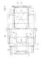
- FIG. 2 shows a section of a view in the axial direction of the conveyor rollers of the frame feeder from FIG. 1.
- the device for packing cigarettes has two step-by-step conveyors 1, 2, in the exemplary embodiment shown with belts 5 and 6 provided with cells 3 and 4, however, revolvers provided with cells can also be used instead.
- Fig. 1 the lower run of the conveyor 1 and the upper run of the conveyor 2 are shown, which are arranged in parallel one above the other and such that the downwardly open cells 3 of the lower run of the conveyor 1 are spaced apart from the upwardly open cells 4 of the upper run the conveyor 2 are.
- the upper conveyor 1 transports inner packages 7 in the cells 3 of its lower run, i.e. Blocks of cigarette wrapped in inner paper.
- the inner paper and the respective cigarette block are fed in the area of the lower run of the respective cell 3 of the conveyor 1 and the inner paper is folded around the respective cigarette block.
- a guide (not shown) is provided which prevents the inner packages 7 from falling out.
- the individual cells 3 and 4 which are fastened to the respective belt 5 and 6, are provided on the bottom side with lateral strips 8 which extend in the conveying direction and are guided in corresponding guide grooves 9 by guide rails 10.
- the individual cells 3, 4 are each open towards the outside and at the end and form a cuboid-shaped receiving space essentially corresponding to the size of a packet of cigarettes.
- a frame feed 11 comprises a feed section for individual frames 12, which opens into a gap between a free-running roller 13 and a driven conveyor roller 14.
- the conveyor roller 14 also works together with a further, also driven conveyor roller 15, an arcuate guide 16 being arranged adjacent to the outer circumference of the conveyor roller 14 between the gap with the roller 13 and the gap with the conveyor roller 15.
- a frame 12 after being gripped by the rollers 13, 14, is conveyed into the gap between the conveyor rollers 14, 15 in order to be conveyed into a horizontal guide slot which is formed by two guides 17, 18 arranged at a short distance from one another.
- a thrower 19 which is arranged in the form of a pivot at one end th lever is formed with a free end angled by approximately 90 °, engages with its free end on the gap between the pair of conveyor rollers 14, 15 leaving frame 12 to this through the guide slot of the guides 17, 18 to a cell 4 of Transport conveyor 2.
- rollers 13, 14, 15 engage the frame 12 in the two transition areas between the two leading outer, lobe-shaped ends and the trailing central area in such a way that the frame 12 is conveyed along its entire length.
- the rollers 13, 14, 15 accordingly each comprise two coaxial roller disks 20 which are arranged at a corresponding distance from one another.
- the frame feed 11 is driven by a drive shaft 21, which drives two coaxial gear wheels 23, 24 via a gear wheel 22, which drive the conveyor roller 14 and the conveyor roller 15.
- a shaft 25 is coupled in a suitable manner to the drive shaft 21 in order to pivot the thrower 19 back and forth.
- the thrower 19 is fork-shaped in the exemplary embodiment shown, at least in the region of its free end, in order to be able to engage the rear edges of the outer, lateral tabs of the respective frame 12.
- the guide 17 has corresponding slots 26 which allow the pivoting movement of the thrower 19.
- the guide 17 and / or the guide 18 can in addition to the lateral guidance of the frames 12 with corresponding webs 27a or the like. be provided.
- the lower guide 17 can be extended on both sides in the conveying direction up to the conveyor 2 and provided with a stop for the frame 12 (shown in broken lines in Fig. 2), so that the frame 12 not directly on the respective cell 4, but is centered and positioned somewhat above this on these lateral extensions of the guide 17.
- a vertical guide 27 is arranged on the side opposite the guides 17, 18, which extends essentially over the height of the cells 3, 4 and the distance between them and adjacent to the cell 3 is provided with a bevel 28, which serves to hold the inner package 7 in the cell 3, since otherwise no underside support can be present in the transfer station.
- a slide 29 is provided, which can be moved up and down along a vertical guide 30 via a crank mechanism 31.
- the slide 29 has an approximately U-shaped frame 32 with inward, Sections 33 running parallel to the bottom section 4a of the cell 3. Since the cells 3 (and 4) have a correspondingly shortened bottom section 4a on both sides, the sections 33 can the inner package 7 on one side on the guide 18 and on the other side on the vertical guide 27 slide out of cell 3 and into cell 4. In this case, the inner package 7 is initially compressed slightly as a result of the bevel 28, in order then to be released again in the area of the cell 4 due to a section 34 of the vertical guide 27 which is set back somewhat there.
- Inner package 7 When the inner package 7 is transferred from the cell 3 to the cell 4, the frame 12 arranged above the cell 4 is folded along its fold lines with its lateral sections by being pressed between the side walls 4b of the cell 4 and pressed into the cell 4 so that it does so Inner package 7 encompasses a total of U-shaped from below both on the bottom side and on both sides.
- a thrower 19 it is also possible, for example, to use a suction device which grips the frame 12 when it leaves the gap between the conveyor rollers 14, 15, conveys it to the desired position and deposits it there.
- the frame 12 can already be conveyed through the frame feed 11 when the respective cell 4 of the conveyor 2 is still in motion, so that the positioning of the frames 12 practically does not extend the transfer time of the inner packages 7 from one conveyor 1 to the other 2.
- a coupon feed 35 which comprises a rotating knife 36 driven by the gear 22 and a stationary knife 37 cooperating therewith, to which a coupon track 38 is fed.
- the knives 36, 37 each separate a coupon from the coupon track 38, the front end of the separated coupon being gripped by a pair of conveyor rollers 39 and the respective coupon being conveyed into the gap between the conveyor rollers 14, 15 onto the respective frame 12, so that the coupon is first conveyed together with the frame 12 by the conveyor rollers 14, 15 and then positioned on the cell 4 by the thrower 19.
- the coupon thus gets between the inner package 7 and the frame 12 or the outer paper glued to it later.
- the conveyor rollers 39 are driven by a gear 40, which is in engagement with a gear 41, which in turn serves to drive the knife 36 and is in engagement with the gear 22.
Applications Claiming Priority (2)
| Application Number | Priority Date | Filing Date | Title |
|---|---|---|---|
| DE3940789 | 1989-12-09 | ||
| DE3940789A DE3940789A1 (de) | 1989-12-09 | 1989-12-09 | Vorrichtung zum verpacken von zigaretten |
Publications (2)
| Publication Number | Publication Date |
|---|---|
| EP0432592A1 true EP0432592A1 (fr) | 1991-06-19 |
| EP0432592B1 EP0432592B1 (fr) | 1993-07-14 |
Family
ID=6395172
Family Applications (1)
| Application Number | Title | Priority Date | Filing Date |
|---|---|---|---|
| EP90123023A Expired - Lifetime EP0432592B1 (fr) | 1989-12-09 | 1990-12-01 | Dispositif d'emballage de cigarettes |
Country Status (6)
| Country | Link |
|---|---|
| US (1) | US5146728A (fr) |
| EP (1) | EP0432592B1 (fr) |
| JP (1) | JPH04173515A (fr) |
| CN (1) | CN1023988C (fr) |
| DE (2) | DE3940789A1 (fr) |
| RU (1) | RU1816274C (fr) |
Cited By (3)
| Publication number | Priority date | Publication date | Assignee | Title |
|---|---|---|---|---|
| EP1854725A1 (fr) * | 2006-05-09 | 2007-11-14 | G.D Societ Per Azioni | Procédé et machine pour empaqueter des groupes de cigarettes |
| CN101070101B (zh) * | 2006-05-09 | 2011-07-06 | 吉第联合股份公司 | 生产香烟盒的方法和包装机 |
| EP2953859A1 (fr) * | 2013-02-05 | 2015-12-16 | Focke & Co. (GmbH & Co.) | Procédé et dispositif permettant de fabriquer des pièces découpées pour des collerettes de paquets de cigarettes |
Families Citing this family (8)
| Publication number | Priority date | Publication date | Assignee | Title |
|---|---|---|---|---|
| IT1264276B1 (it) * | 1993-11-24 | 1996-09-23 | Gd Spa | Apparecchiatura per l'applicazione di etichette di sigillo a contenitori. |
| DE19602192A1 (de) * | 1996-01-23 | 1997-07-24 | Topack Verpacktech Gmbh | Verfahren und Vorrichtung zum Überführen eines Kragenzuschnitts für eine Zigarettenpackung in eine Aufnahmetasche eines Verpackungsförderers |
| IT1293236B1 (it) * | 1997-07-09 | 1999-02-16 | Gd Spa | Metodo ed unita' di alimentazione di collari per pacchetti rigidi di sigarette ad una linea di impacchettamento continua. |
| GB9716899D0 (en) * | 1997-08-08 | 1997-10-15 | Rothmans International Ltd | Machine and process for packaging smoking articles |
| US6427423B1 (en) | 2000-02-14 | 2002-08-06 | Brown & Williamson Tobacco Corporation | Coupon inserter for hinge lid pack |
| DE10056407A1 (de) * | 2000-11-14 | 2002-05-23 | Topack Verpacktech Gmbh | Einrichtung und Verfahren zum Überführen eines Flächengebildes |
| DE10056403A1 (de) * | 2000-11-14 | 2002-05-23 | Topack Verpacktech Gmbh | Verfahren und Vorrichtung zum Überführen eines Flächengebildes |
| CN104528017B (zh) * | 2014-12-23 | 2016-04-27 | 湖北工业大学 | 一种摇盖式大开口固定烟盒装盒工艺和装置 |
Citations (3)
| Publication number | Priority date | Publication date | Assignee | Title |
|---|---|---|---|---|
| EP0082348A2 (fr) * | 1981-12-19 | 1983-06-29 | Focke & Co. (GmbH & Co.) | Appareil pour introduire des groupes de cigarettes dans des paquets de cigarettes |
| US4771882A (en) * | 1987-06-24 | 1988-09-20 | Brown & Williamson Tobacco Corporation | Cigarette package with spacer |
| EP0324160A1 (fr) * | 1988-01-13 | 1989-07-19 | Focke & Co. (GmbH & Co.) | Procédé et dispositif pour la fabrication de boîtes avec un couvercle à charnière, munies d'une couronne, en particulier pour cigarettes |
Family Cites Families (9)
| Publication number | Priority date | Publication date | Assignee | Title |
|---|---|---|---|---|
| JPS4891300A (fr) * | 1972-02-11 | 1973-11-28 | ||
| IT1000890B (it) * | 1973-11-21 | 1976-04-10 | Gd Spa | Macchina impacchettatrice di sigarette veloce |
| IT1001428B (it) * | 1973-12-20 | 1976-04-20 | Gd Spa | Dispositivo di trasferimento e di predisposizione all utilizzo dei cosiddetti elementi interni o col letti nelle macchine condizionatri ci di sigarette in pacchetti rigi di del tipo a coperchio incerniera to |
| DE2440006C2 (de) * | 1974-08-21 | 1984-06-28 | Focke & Co, 2810 Verden | Verfahren und Vorrichtung zum Herstellen von (quaderförmigen) Klappschachteln |
| IT1060843B (it) * | 1976-03-17 | 1982-09-30 | Gd Spa | Dispositivo perfezionato per la piegatura delle testate degli in volucri interni nelle macchine condizionatrici di sigarette in pacchetti rigidi del tipo a coperchio incernierato |
| US4179864A (en) * | 1976-07-22 | 1979-12-25 | Focke & Pfuhl | Apparatus for setting and shaping glued cigarette packs |
| IT1158537B (it) * | 1982-12-28 | 1987-02-18 | Sasib Spa | Macchina automatica impacchettatrice di sigarette in pacchetti rigidi in particolare in pacchetti del tipo con coperchio a cerniera |
| DE3333053A1 (de) * | 1983-09-14 | 1985-03-21 | Focke & Co, 2810 Verden | Vorrichtung zum herstellen von packungen, insbesondere zigaretten-stangen |
| DE3802644C2 (de) * | 1988-01-29 | 1999-10-07 | Focke & Co | Verfahren und Vorrichtung zum Herstellen von Klappschachteln für Zigaretten |
-
1989
- 1989-12-09 DE DE3940789A patent/DE3940789A1/de not_active Withdrawn
-
1990
- 1990-12-01 EP EP90123023A patent/EP0432592B1/fr not_active Expired - Lifetime
- 1990-12-01 DE DE9090123023T patent/DE59001967D1/de not_active Expired - Fee Related
- 1990-12-07 JP JP2407389A patent/JPH04173515A/ja active Pending
- 1990-12-07 RU SU904831761A patent/RU1816274C/ru active
- 1990-12-07 US US07/623,608 patent/US5146728A/en not_active Expired - Fee Related
- 1990-12-08 CN CN90109964A patent/CN1023988C/zh not_active Expired - Fee Related
Patent Citations (3)
| Publication number | Priority date | Publication date | Assignee | Title |
|---|---|---|---|---|
| EP0082348A2 (fr) * | 1981-12-19 | 1983-06-29 | Focke & Co. (GmbH & Co.) | Appareil pour introduire des groupes de cigarettes dans des paquets de cigarettes |
| US4771882A (en) * | 1987-06-24 | 1988-09-20 | Brown & Williamson Tobacco Corporation | Cigarette package with spacer |
| EP0324160A1 (fr) * | 1988-01-13 | 1989-07-19 | Focke & Co. (GmbH & Co.) | Procédé et dispositif pour la fabrication de boîtes avec un couvercle à charnière, munies d'une couronne, en particulier pour cigarettes |
Cited By (4)
| Publication number | Priority date | Publication date | Assignee | Title |
|---|---|---|---|---|
| EP1854725A1 (fr) * | 2006-05-09 | 2007-11-14 | G.D Societ Per Azioni | Procédé et machine pour empaqueter des groupes de cigarettes |
| CN101070100B (zh) * | 2006-05-09 | 2011-04-13 | 吉第联合股份公司 | 用于包装香烟组的方法及机器 |
| CN101070101B (zh) * | 2006-05-09 | 2011-07-06 | 吉第联合股份公司 | 生产香烟盒的方法和包装机 |
| EP2953859A1 (fr) * | 2013-02-05 | 2015-12-16 | Focke & Co. (GmbH & Co.) | Procédé et dispositif permettant de fabriquer des pièces découpées pour des collerettes de paquets de cigarettes |
Also Published As
| Publication number | Publication date |
|---|---|
| EP0432592B1 (fr) | 1993-07-14 |
| US5146728A (en) | 1992-09-15 |
| CN1053909A (zh) | 1991-08-21 |
| DE3940789A1 (de) | 1991-06-13 |
| JPH04173515A (ja) | 1992-06-22 |
| DE59001967D1 (de) | 1993-08-19 |
| RU1816274C (ru) | 1993-05-15 |
| CN1023988C (zh) | 1994-03-16 |
Similar Documents
| Publication | Publication Date | Title |
|---|---|---|
| DE2500569C2 (de) | Vorrichtung zum Verpacken von Gegenständen in ein Hüllmaterial | |
| EP0071736B1 (fr) | Dispositif d'emballage pour la fabrication de découpes et pour amener celles-ci à une station d'emballage | |
| AT397370B (de) | Vorrichtung zum sammeln von gefalzten druckbogen | |
| DE2407767C3 (de) | Verfahren und Vorrichtung zum Einschlagen von Zigarettengruppen o.dgl | |
| DE2350111C3 (de) | Bodenfaltungspacker | |
| DE2447917C2 (de) | Vorrichtung zum Herstellen von Kragen für den Einsatz in die Öffnung von steifen Zigarettenpackungen mit Klappendeckel | |
| DE3529071C2 (de) | Vorrichtung zum Stapeln von Packungseinheiten | |
| DE3042519A1 (de) | Vorrichtung zum stapeln von produkten | |
| CH649267A5 (de) | Verfahren und vorrichtung zum einbringen wenigstens einer einlage in druckprodukte. | |
| EP0304736B1 (fr) | Procédé et dispositif pour envelopper spécialement des paquets de cigarettes | |
| EP0432592B1 (fr) | Dispositif d'emballage de cigarettes | |
| DE3338036C2 (de) | Vorrichtung zum Umwickeln von Packstücken oder Gebinden in einer Stretchfolie | |
| EP0305956A2 (fr) | Dispositif pour emballer des barres cylindriques composées d'une pluralité de pièces discoides | |
| DE2718912C2 (fr) | ||
| EP0210494B1 (fr) | Dispositif de rassemblement pour feuilles pliées | |
| DE4127854C2 (de) | Vorrichtung zum Zuführen von zwei plattenförmigen Zuschnitten zu einer Tiefziehmaschine | |
| DE2624812A1 (de) | Einwickelmaschine | |
| DE60309613T2 (de) | Verfahren und Vorrichtung zum Zuführen von Blattmaterial zu einer Produkteinwickelstrasse | |
| DE2136692A1 (de) | Verfahren und Vorrichtung zum Sammeln und Abtransportieren von Be haltern | |
| EP1201541A1 (fr) | Procédé et dispositif pour l'enveloppement des paquets des produits dans l'industrie du tabac | |
| DE3102203C2 (fr) | ||
| CH440105A (de) | Doppelbahniger Querpacker | |
| EP0328875A2 (fr) | Procédé et dispositif de séparation d'articles plans | |
| EP1050463B1 (fr) | Machine de liage pour lier une pile d'objets | |
| DE3515655A1 (de) | Verfahren und vorrichtung zum umhuellen von packungen mit huellmaterial |
Legal Events
| Date | Code | Title | Description |
|---|---|---|---|
| PUAI | Public reference made under article 153(3) epc to a published international application that has entered the european phase |
Free format text: ORIGINAL CODE: 0009012 |
|
| 17P | Request for examination filed |
Effective date: 19901220 |
|
| AK | Designated contracting states |
Kind code of ref document: A1 Designated state(s): DE FR GB IT |
|
| 17Q | First examination report despatched |
Effective date: 19921211 |
|
| GRAA | (expected) grant |
Free format text: ORIGINAL CODE: 0009210 |
|
| AK | Designated contracting states |
Kind code of ref document: B1 Designated state(s): DE FR GB IT |
|
| GBT | Gb: translation of ep patent filed (gb section 77(6)(a)/1977) |
Effective date: 19930713 |
|
| REF | Corresponds to: |
Ref document number: 59001967 Country of ref document: DE Date of ref document: 19930819 |
|
| ET | Fr: translation filed | ||
| ITF | It: translation for a ep patent filed |
Owner name: STUDIO TORTA SOCIETA' SEMPLICE |
|
| PLBE | No opposition filed within time limit |
Free format text: ORIGINAL CODE: 0009261 |
|
| STAA | Information on the status of an ep patent application or granted ep patent |
Free format text: STATUS: NO OPPOSITION FILED WITHIN TIME LIMIT |
|
| 26N | No opposition filed | ||
| PGFP | Annual fee paid to national office [announced via postgrant information from national office to epo] |
Ref country code: FR Payment date: 19961216 Year of fee payment: 7 |
|
| PG25 | Lapsed in a contracting state [announced via postgrant information from national office to epo] |
Ref country code: FR Free format text: THE PATENT HAS BEEN ANNULLED BY A DECISION OF A NATIONAL AUTHORITY Effective date: 19971231 |
|
| REG | Reference to a national code |
Ref country code: FR Ref legal event code: ST |
|
| REG | Reference to a national code |
Ref country code: GB Ref legal event code: IF02 |
|
| PGFP | Annual fee paid to national office [announced via postgrant information from national office to epo] |
Ref country code: GB Payment date: 20041122 Year of fee payment: 15 |
|
| PGFP | Annual fee paid to national office [announced via postgrant information from national office to epo] |
Ref country code: DE Payment date: 20050209 Year of fee payment: 15 |
|
| PG25 | Lapsed in a contracting state [announced via postgrant information from national office to epo] |
Ref country code: IT Free format text: LAPSE BECAUSE OF NON-PAYMENT OF DUE FEES;WARNING: LAPSES OF ITALIAN PATENTS WITH EFFECTIVE DATE BEFORE 2007 MAY HAVE OCCURRED AT ANY TIME BEFORE 2007. THE CORRECT EFFECTIVE DATE MAY BE DIFFERENT FROM THE ONE RECORDED. Effective date: 20051201 Ref country code: GB Free format text: LAPSE BECAUSE OF NON-PAYMENT OF DUE FEES Effective date: 20051201 |
|
| PG25 | Lapsed in a contracting state [announced via postgrant information from national office to epo] |
Ref country code: DE Free format text: LAPSE BECAUSE OF NON-PAYMENT OF DUE FEES Effective date: 20060701 |
|
| GBPC | Gb: european patent ceased through non-payment of renewal fee |
Effective date: 20051201 |