EP0432484A2 - Fastening element - Google Patents
Fastening element Download PDFInfo
- Publication number
- EP0432484A2 EP0432484A2 EP90121704A EP90121704A EP0432484A2 EP 0432484 A2 EP0432484 A2 EP 0432484A2 EP 90121704 A EP90121704 A EP 90121704A EP 90121704 A EP90121704 A EP 90121704A EP 0432484 A2 EP0432484 A2 EP 0432484A2
- Authority
- EP
- European Patent Office
- Prior art keywords
- composite
- composite element
- flange
- wooden
- shaft
- Prior art date
- Legal status (The legal status is an assumption and is not a legal conclusion. Google has not performed a legal analysis and makes no representation as to the accuracy of the status listed.)
- Granted
Links
- 239000002131 composite material Substances 0.000 claims abstract description 184
- 239000004567 concrete Substances 0.000 claims abstract description 49
- 238000010276 construction Methods 0.000 claims abstract description 35
- 238000011065 in-situ storage Methods 0.000 claims abstract description 26
- 230000003014 reinforcing effect Effects 0.000 claims abstract description 4
- 230000001154 acute effect Effects 0.000 claims description 13
- 239000002023 wood Substances 0.000 claims description 12
- 230000007704 transition Effects 0.000 claims description 7
- 239000011248 coating agent Substances 0.000 claims description 6
- 238000000576 coating method Methods 0.000 claims description 6
- 238000005553 drilling Methods 0.000 claims description 5
- 239000002184 metal Substances 0.000 claims description 4
- 239000011093 chipboard Substances 0.000 claims description 3
- 238000007514 turning Methods 0.000 claims description 3
- 238000010079 rubber tapping Methods 0.000 claims description 2
- 239000002985 plastic film Substances 0.000 abstract description 11
- 229920006255 plastic film Polymers 0.000 abstract description 11
- 238000004519 manufacturing process Methods 0.000 abstract description 8
- 230000002787 reinforcement Effects 0.000 abstract description 5
- 230000006872 improvement Effects 0.000 description 7
- 238000004873 anchoring Methods 0.000 description 6
- 238000009413 insulation Methods 0.000 description 6
- 238000000034 method Methods 0.000 description 6
- 238000009418 renovation Methods 0.000 description 6
- 230000008569 process Effects 0.000 description 5
- 230000008901 benefit Effects 0.000 description 4
- 238000009415 formwork Methods 0.000 description 3
- 239000000463 material Substances 0.000 description 3
- 239000004576 sand Substances 0.000 description 3
- 239000002893 slag Substances 0.000 description 3
- 229910000831 Steel Inorganic materials 0.000 description 2
- 238000004364 calculation method Methods 0.000 description 2
- 230000000694 effects Effects 0.000 description 2
- 238000005516 engineering process Methods 0.000 description 2
- 239000003292 glue Substances 0.000 description 2
- 238000009434 installation Methods 0.000 description 2
- 239000011505 plaster Substances 0.000 description 2
- 238000003825 pressing Methods 0.000 description 2
- 239000011150 reinforced concrete Substances 0.000 description 2
- 239000010959 steel Substances 0.000 description 2
- 230000035508 accumulation Effects 0.000 description 1
- 238000009825 accumulation Methods 0.000 description 1
- 238000005452 bending Methods 0.000 description 1
- 239000011230 binding agent Substances 0.000 description 1
- 230000005540 biological transmission Effects 0.000 description 1
- 239000004566 building material Substances 0.000 description 1
- 238000007667 floating Methods 0.000 description 1
- 239000011810 insulating material Substances 0.000 description 1
- 239000007788 liquid Substances 0.000 description 1
- 238000003754 machining Methods 0.000 description 1
- 230000000149 penetrating effect Effects 0.000 description 1
- 230000008092 positive effect Effects 0.000 description 1
- 230000009467 reduction Effects 0.000 description 1
- 239000000523 sample Substances 0.000 description 1
- 238000007789 sealing Methods 0.000 description 1
- 239000007787 solid Substances 0.000 description 1
- 238000003860 storage Methods 0.000 description 1
- 238000004381 surface treatment Methods 0.000 description 1
- 230000003313 weakening effect Effects 0.000 description 1
- 238000003466 welding Methods 0.000 description 1
Images
Classifications
-
- E—FIXED CONSTRUCTIONS
- E04—BUILDING
- E04B—GENERAL BUILDING CONSTRUCTIONS; WALLS, e.g. PARTITIONS; ROOFS; FLOORS; CEILINGS; INSULATION OR OTHER PROTECTION OF BUILDINGS
- E04B1/00—Constructions in general; Structures which are not restricted either to walls, e.g. partitions, or floors or ceilings or roofs
- E04B1/16—Structures made from masses, e.g. of concrete, cast or similarly formed in situ with or without making use of additional elements, such as permanent forms, substructures to be coated with load-bearing material
- E04B1/164—Structures made from masses, e.g. of concrete, cast or similarly formed in situ with or without making use of additional elements, such as permanent forms, substructures to be coated with load-bearing material with vertical and horizontal slabs, only the horizontal slabs being partially cast in situ
-
- E—FIXED CONSTRUCTIONS
- E04—BUILDING
- E04B—GENERAL BUILDING CONSTRUCTIONS; WALLS, e.g. PARTITIONS; ROOFS; FLOORS; CEILINGS; INSULATION OR OTHER PROTECTION OF BUILDINGS
- E04B5/00—Floors; Floor construction with regard to insulation; Connections specially adapted therefor
- E04B5/16—Load-carrying floor structures wholly or partly cast or similarly formed in situ
- E04B5/17—Floor structures partly formed in situ
- E04B5/23—Floor structures partly formed in situ with stiffening ribs or other beam-like formations wholly or partly prefabricated
-
- E—FIXED CONSTRUCTIONS
- E04—BUILDING
- E04G—SCAFFOLDING; FORMS; SHUTTERING; BUILDING IMPLEMENTS OR AIDS, OR THEIR USE; HANDLING BUILDING MATERIALS ON THE SITE; REPAIRING, BREAKING-UP OR OTHER WORK ON EXISTING BUILDINGS
- E04G23/00—Working measures on existing buildings
- E04G23/02—Repairing, e.g. filling cracks; Restoring; Altering; Enlarging
- E04G23/0218—Increasing or restoring the load-bearing capacity of building construction elements
-
- F—MECHANICAL ENGINEERING; LIGHTING; HEATING; WEAPONS; BLASTING
- F16—ENGINEERING ELEMENTS AND UNITS; GENERAL MEASURES FOR PRODUCING AND MAINTAINING EFFECTIVE FUNCTIONING OF MACHINES OR INSTALLATIONS; THERMAL INSULATION IN GENERAL
- F16B—DEVICES FOR FASTENING OR SECURING CONSTRUCTIONAL ELEMENTS OR MACHINE PARTS TOGETHER, e.g. NAILS, BOLTS, CIRCLIPS, CLAMPS, CLIPS OR WEDGES; JOINTS OR JOINTING
- F16B35/00—Screw-bolts; Stay-bolts; Screw-threaded studs; Screws; Set screws
- F16B35/04—Screw-bolts; Stay-bolts; Screw-threaded studs; Screws; Set screws with specially-shaped head or shaft in order to fix the bolt on or in an object
- F16B35/041—Specially-shaped shafts
-
- E—FIXED CONSTRUCTIONS
- E04—BUILDING
- E04B—GENERAL BUILDING CONSTRUCTIONS; WALLS, e.g. PARTITIONS; ROOFS; FLOORS; CEILINGS; INSULATION OR OTHER PROTECTION OF BUILDINGS
- E04B5/00—Floors; Floor construction with regard to insulation; Connections specially adapted therefor
- E04B5/16—Load-carrying floor structures wholly or partly cast or similarly formed in situ
- E04B5/17—Floor structures partly formed in situ
- E04B5/23—Floor structures partly formed in situ with stiffening ribs or other beam-like formations wholly or partly prefabricated
- E04B2005/232—Floor structures partly formed in situ with stiffening ribs or other beam-like formations wholly or partly prefabricated with special provisions for connecting wooden stiffening ribs or other wooden beam-like formations to the concrete slab
- E04B2005/237—Separate connecting elements
-
- E—FIXED CONSTRUCTIONS
- E04—BUILDING
- E04G—SCAFFOLDING; FORMS; SHUTTERING; BUILDING IMPLEMENTS OR AIDS, OR THEIR USE; HANDLING BUILDING MATERIALS ON THE SITE; REPAIRING, BREAKING-UP OR OTHER WORK ON EXISTING BUILDINGS
- E04G23/00—Working measures on existing buildings
- E04G23/02—Repairing, e.g. filling cracks; Restoring; Altering; Enlarging
- E04G23/0218—Increasing or restoring the load-bearing capacity of building construction elements
- E04G2023/0248—Increasing or restoring the load-bearing capacity of building construction elements of elements made of wood
-
- F—MECHANICAL ENGINEERING; LIGHTING; HEATING; WEAPONS; BLASTING
- F16—ENGINEERING ELEMENTS AND UNITS; GENERAL MEASURES FOR PRODUCING AND MAINTAINING EFFECTIVE FUNCTIONING OF MACHINES OR INSTALLATIONS; THERMAL INSULATION IN GENERAL
- F16B—DEVICES FOR FASTENING OR SECURING CONSTRUCTIONAL ELEMENTS OR MACHINE PARTS TOGETHER, e.g. NAILS, BOLTS, CIRCLIPS, CLAMPS, CLIPS OR WEDGES; JOINTS OR JOINTING
- F16B25/00—Screws that cut thread in the body into which they are screwed, e.g. wood screws
Definitions
- the present invention has now set itself the task of creating a composite element of the type mentioned, which brings with it optimal possibilities for this special purpose.
- a circumferential collar radially projecting beyond the head is formed on the shaft of the composite element designed to engage a turning tool, and that a flange is arranged at a distance from the head on the shaft of the composite element, the flange and flange at least approximately have the same outer dimensions, and that at least the portion of the shaft facing away from the head with respect to the flange is formed with a thread at least over part of the length of this section for screwing the composite element into a wooden beam or beam.
- the collar formed at the head of the composite element results in a significantly improved anchoring in the concrete applied to the wooden structure, so that the tensile forces that arise in addition to the shear forces between the two composite layers and act in the axial direction of the composite elements can be optimally transmitted. It is therefore practically possible to compare the pull-out values of the composite element with respect to the wooden beams or beams with equivalent pull-out values in the anchoring in concrete.
- a significant improvement is the additional arrangement of a flange on the shaft of the composite element, with the appropriate distance from the head of the composite element.
- a plastic film is applied to the wooden ceiling to prevent moisture from penetrating into the wooden structure during the concreting process.
- the arrangement of the additional flange on the shaft of the composite element completely seals the opening resulting from the screwing of the composite element into the wooden beam or beam, since this plastic film in each case in the entire area surrounding the opening through the flange against the wooden formwork or the wooden floor is pressed.
- the collar and flange are designed as cylindrical sections of the same diameter. It is also advantageous if the collar and flange measured in the axial direction of the composite element have the same thickness. There are therefore similarly large material accumulations in the area of the federal government and in the area of the flange, which has a positive effect on the manufacturing technology during forming.
- the diameter of the collar and flange correspond at least approximately to twice the shaft diameter. This results in an optimal anchoring of the composite element in the area of the head, which protrudes into the concrete layer, and on the other hand, proper support and pressing of the wooden structure and on this for the plastic film is guaranteed.
- the diameter of the shaft in the area between the collar and flange corresponds at least approximately to the outside diameter of the threaded area on the shaft.
- the thread on the shaft is designed in the manner of a self-tapping screw thread and the ratio of Core diameter to outside diameter is approximately 1: 1.2 to 1: 1.6. It has been shown that the composite element with such a thread shape can be screwed directly into the wooden structure without pre-drilling a hole, and in addition the screwing devices used can in no way be overloaded. The special choice of the ratio of the core diameter to the outside diameter of the screw thread ensures an optimal engagement between the composite element and the wooden beam or beam, whereby the splitting effect feared with wood is avoided.
- the thread on the shaft it is also possible for the thread on the shaft to be designed in the manner of a wood screw, chipboard or sheet metal thread with the largest possible ratio of core diameter to outside diameter.
- the pull-out values are much higher with such a thread.
- the free end of the shaft is designed as a drilling tip or a milled tip.
- the axial distance between the collar and flange is approximately one third of the total length of the composite element.
- the composite element engages two thirds of its length in the wooden structure and approximately one third of its length in the in-situ concrete slab.
- An advantageous feature is also provided by the fact that a shoulder which widens conically towards the flange is provided on the transition region between the shaft and flange, this transition region preferably running in an arc shape when viewed in cross section.
- a further improvement in the sealing effect by pressing the plastic film can be achieved if the flange on its thread-side boundary surface has a projecting ring section on its outer edge area which is aligned coaxially with the shaft.
- the composite element according to the invention is to be screwed into a wooden beam or support, there is a substantial reduction in the screwing torque if at least the threaded area of the composite element is provided with a wax coating or another coating that reduces friction during screwing.
- the composite elements can be screwed into the wooden beams or beams next to one another in pairs, the two composite elements of the pair being inclined to one another in opposite directions.
- pairs of composite elements can be arranged at equal or changing distances from one another, although it may also be expedient if these pairs follow one another towards the ends of the wooden beams at a shorter distance than in the Middle area of the wooden beam is the case.
- an advantageous embodiment variant is that the composite elements, viewed in the longitudinal direction of the wooden beam or beam, are each arranged in pairs at a distance from one another, the composite elements of each pair res enclose a right or acute angle with each other so that the head areas of the two composite elements of each pair are inclined towards each other with a small distance from one another.
- a form of truss girder is created, which enables an optimal mutual bond and thus further reduces the deflection of such a composite structure. It will therefore be possible to reduce the deflection of a composite construction according to the invention by more than 50%.
- the composite elements can be attached in one or more rows with respect to a wooden beam, the axes of the composite elements then lying in one or in two or more vertical planes lying parallel to one another and intended in the longitudinal direction of the wooden beam or beam.
- the composite elements are screwed in at an acute angle to the upper side and transversely to the longitudinal direction of the wooden beam or support.
- Such an arrangement of the composite elements can either be in addition to the composite elements inclined in the other direction, i.e. in the longitudinal direction of the wooden beam, or it would also be conceivable to screw in all composite elements inclined in the direction transverse to the longitudinal direction of the wooden beam, even in such a case two composite elements could be arranged side by side in pairs.
- the composite elements prefferably be screwed in at an angle both in the longitudinal direction and transversely to the wooden beam or support, that is to say with their longitudinal axis lying in a plane intended by a wooden beam or support at an acute angle to the longitudinal vertical plane.
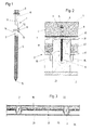
- the composite element 1 shown in FIG. 1 is used as a connection between a supporting structure 3 having a wooden beam 2 and an in-situ concrete slab 4.
- the composite element 1 essentially consists of a head 5, a collar 6, a shaft 7, a flange 8 and a thread 9 with a screw-in tip 10.
- the head 5 is designed to engage a turning tool, an external drive being shown in the drawing. But it would be quite conceivable to provide an internal drive on the head 5.
- Connected to the head 5 on the shaft side is the circumferential collar 6 which projects radially beyond the head 5.
- the flange 8 is arranged at a distance from the head 5 and thus also from the collar 6 on the shaft 7.
- the collar 6 and the flange 8 expediently have at least approximately the same external dimensions.
- the thread 9 is provided on the section of the shaft 7 facing away from the head 5 with respect to the flange 8 and serves to screw the composite element into the wooden beam 2.
- the flange 8 is integrally formed on the shaft 7.
- Both the collar 6 and the flange 8 are designed as cylindrical sections of the same diameter and, moreover, expediently have the same thickness when viewed in the axial direction of the composite element 1.
- the diameter of the collar 6 and the flange 8 corresponds at least approximately to twice the shaft diameter.
- the diameter of the shaft 7 in the area between the collar 6 and the flange 8 corresponds at least approximately to the outside diameter of the thread 9 on the shaft 7.
- the shaft section 11 in the area between the collar 6 and the flange 8 is expediently thread-free. It would be quite conceivable to design this shaft area 11 in a grooved manner, but this is not necessary with regard to the correct mutual fastening of the composite parts. This would also cause a cross-sectional weakening in the event of buckling loads.
- the thread 9 can be designed, for example, as a wood screw thread.
- a wood screw, chipboard or sheet metal thread With a wood screw, chipboard or sheet metal thread, the ratio between core diameter and outside diameter can be chosen to be relatively large, so that the pull-out values are very high.
- a thread 9 in the manner of a sheet metal screw thread is also advantageous, in which case the ratio of core diameter to outside diameter is approximately 1: 1.2 to 1: 1.6.
- Such an embodiment of the thread for the composite element according to the invention provides a core diameter of 5.15 mm and an outer thread diameter of 6.5 mm.
- the thread pitch is 2.54 mm.
- excellent pull-out values can be achieved in spite of the relatively small ratio between the core and outer diameter, and there is also the guarantee that when the composite element is screwed in neither a pre-drilling is necessary nor a risk of splitting for the wooden beam 2.
- the shaft could also be designed with a larger diameter, in which case the diameter of the collar and the shaft need not necessarily be twice as large.
- the axial distance between the collar 6 and the flange 8 is approximately one third of the total length of the composite element 1.
- an arcuate cross section is provided at the transition areas 12 and 13 between the shaft 7 or shaft section 11 and the flange 8. It would also be conceivable to provide a shoulder which widens conically towards the flange 8 at the transition region 12 or 13 between the shaft 7 and the flange 8.
- the flange 8 could have a special design, specifically this could have on its thread-side boundary surface 14 on its outer edge region a projecting ring section aligned coaxially to the shaft. A special contact pressure against the upper side of the wooden structure would be possible, particularly at the outer edge region of the flange 8.
- the entire composite element can be subjected to a surface treatment. This would make a galvanized version possible or just a blackened version.
- a surface treatment With regard to the screwing in of the composite element into wood, it is expedient if at least the threaded area of the composite element 1 is provided with a wax coating or another coating which reduces the friction during screwing in.
- the composite element according to the invention it would also be possible with the composite element according to the invention to manufacture it from rust-free material. However, since the composite element is not exposed to the weather or the atmosphere in this special type of application, such an embodiment can be dispensed with here.
- the composite elements 1 according to the invention are expediently screwed into the wooden beams 2 with a screwdriver or a special setting tool, the collar 6 and the flange 8 in cooperation with a wrench nut being able to be used for proper guidance in a wrench channel. It is then expedient if the diameter of collar 6 and flange 8 corresponds at least approximately to the outside diameter of a wrench nut that can be attached to head 5.
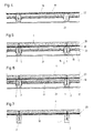
- FIGS. 3 and 4 show the structure of an old ceiling, in which connection reference is also made to FIGS. 3 and 4.
- wooden beams 2 are arranged parallel to one another and run from wall to wall.
- slats 15 and 16 are attached, on which sloping or blind floors 17 are placed.
- 2 sand or slag fillings were placed on the sloping or blind floors 17 between the individual wooden beams.
- the floor boards 18 rested on the wooden beams 2 and were e.g. fixed with nails or screws.
- the old floor covering 19 shown in FIG. 4 must now be removed. Position, dimensions and condition of the wooden beams 2 can then be determined using probe openings. In particular, the condition of the supports on the outer walls is carefully checked. Now the board layer 18 is covered with a plastic film 20 in order to achieve a seal against the entire wooden structure. By applying in-situ concrete, there is a corresponding amount of moisture or liquid that would otherwise penetrate the wooden structure. Now the composite elements 1 are screwed through the plastic film 20 and the board layer 18 into the wooden beam 2 without pre-drilling. The special thread on the composite element ensures high tensile and shear resistance of the composite elements and thus a high load capacity of the entire system.
- the in-situ concrete slab 4 can be manufactured. It is therefore expedient to use normal concrete with a maximum grain size of 8 mm. Lightweight concrete usually has a modulus of elasticity that is too low. The thickness of the in-situ concrete slab 4 is normally 8 cm. As such, it should not be less than 6 cm. For very high demands on sound insulation and load-bearing capacity, panel thicknesses of 10 - 12 cm are possible. Depending on the structure of the ceiling and the required sound insulation, a floating screed can also be installed. At most, a carpet placed on the in-situ concrete slab 4 with the necessary measure of improvement is sufficient.
- the sand or slag filling 22 filled in the ceiling construction can remain in the ceiling construction.
- FIG. 6 shows an exemplary embodiment in which the board layer 18 shown in FIG. 2, that is to say the original floor, has been removed. This is e.g. necessary if the height conditions in a room to be renovated are scarce, so that every centimeter of the room height is important.
- a lightweight building material or an incombustible insulating material 23 is then placed over the sloping or blind floor 17 with sufficient rigidity. Debris, sand or slag 22 lying on the sloping or blind floor 17 can be removed or also left.
- FIG. 7 An embodiment according to FIG. 7 is generally used in a construction process in a new building, but can also be used in the same way for the renovation of old buildings.
- the wooden beams 2 lie freely below a wooden casing 18.
- the plastic film 20 is in turn placed on this wooden casing 18, after which the in-situ concrete slab 4 is applied after the composite elements 1 have been screwed in.
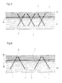
- FIG. 8 shows the arrangement according to the invention of the composite elements 1 in the composite construction, specifically on the basis of a longitudinal section through a composite construction along a wooden beam 2. It can be seen from this that the composite elements 1 in a boundary surface formed by the upper side 30 of the wooden beam 2 acute angles are screwed into the wooden beams. The composite elements 1 which follow one another in the longitudinal direction of the wooden beam 2 are screwed into the wooden beams 2 in an inclined manner in opposite directions, so that a type of truss is created.
- the composite elements 1 are screwed in pairs next to each other into the wooden beam 2, the two composite elements te 1 of the pair are mutually inclined in the opposite direction.
- This special construction creates an optimally effective composite construction between the wooden beams 2 and the in-situ concrete slab 4, so that large tensile and compressive forces can also be absorbed. This limits the deflection to a minimum.
- the composite elements 1 can be screwed in pairs in succession, with the composite elements 1 of each pair forming a right or acute angle with one another.
- the head regions of the two composite elements are thus inclined towards one another and are only a short distance apart.
- This “oblique” arrangement of the composite elements 1 can also be carried out in a multiple arrangement, so that such composite elements are screwed into the top 30 of the wooden beam 2 in one or more planes next to one another, that is to say laterally offset from one another.
- a further variant provides that the composite elements 1 form an acute angle to the upper side 30 of the wooden beam 2, the axis of such a composite element 1, however, lying in a plane that is intended by the wooden beam 2 at an acute angle to the longitudinal vertical plane.
- the composite element according to the invention is therefore not only to be used in the renovation of old buildings, but also in all types of new buildings.
- examples were used to explain the structure of the ceiling, ie the floor.
- the composite element according to the invention can also be used in the wall area, where an in-situ concrete slab made of normal or lightweight concrete is to be anchored in a composite with a wall construction part made of wood.
- Another area of application of the composite element according to the invention is e.g. when building bridges, especially where old wooden bridges are to be renovated.
- the load-bearing capacity of old wooden bridges could be improved here, and it would therefore be easier to make decisions to preserve old wooden bridges if they could be renovated in a simple and safe manner by means of appropriate reinforcement using applied in-situ concrete layers.
Landscapes
- Engineering & Computer Science (AREA)
- Architecture (AREA)
- Civil Engineering (AREA)
- Structural Engineering (AREA)
- Mechanical Engineering (AREA)
- Electromagnetism (AREA)
- Physics & Mathematics (AREA)
- General Engineering & Computer Science (AREA)
- Chemical & Material Sciences (AREA)
- Chemical Kinetics & Catalysis (AREA)
- Electrochemistry (AREA)
- Joining Of Building Structures In Genera (AREA)
- Flanged Joints, Insulating Joints, And Other Joints (AREA)
- Finger-Pressure Massage (AREA)
- Dowels (AREA)
Abstract
Zur Herstellung einer Holz-Beton-Verbundkonstruktion wird ein Verbundelement (1) eingesetzt, welches einen mit einem Gewinde (9) versehenen Abschnitt zum Einschrauben in einen Holzbalken (2) aufweist und andererseits einen Kopf (5), welcher als Armierungsteil zum Eingriff in eine Ortbetonplatte (4) ausgebildet ist. Der Kopf (5) des Verbundelementes (1) weist schaftseitig einen umlaufenden Bund (6) auf. Mit Abstand vom Kopf (5) ist am Schaft (7) ein Flansch (8) angeordnet. Das Verbundelement (1) wird durch eine Bretterauflage (18) in den Holzbalken (2) eingeschraubt, bis der Flansch (8) an der Oberseite der Bretterauflage (18) angepresst ist. Es wird dadurch auch eine auf die Bretterauflage (18) aufgelegte Plastikfolie (20) mitangepresst und abgedichtet. Nach Einsetzen einer entsprechenden Armierung wird zur Bildung der Ortbetonplatte (4) Ortbeton aufgebracht. Die Holzkonstruktion und die aufgebrachte Ortbetonplatte (4) bilden im Zusammenwirken mit dem Verbundelement (1) eine tragfähige Holz-Beton-Verbundkonstruktion. 
Description
Die Erfindung betrifft ein Verbundelement zum Einsatz als Verbindung zwischen einem Holzbalken bzw. -träger aufweisenden Tragwerk und einer Ortbetonplatte, wobei ein mit einem Gewinde versehener Abschnitt des Verbundelementes in die Holzbalken bzw. -träger einschraubbar und der Kopfbereich des Verbundelementes als Armierungsteil zum Eingriff in die Ortbetonplatte ausgebildet ist.The invention relates to a composite element for use as a connection between a wooden beam or support structure and an in-situ concrete slab, wherein a threaded portion of the composite element can be screwed into the wooden beam or support and the head region of the composite element as a reinforcing part for engagement in the In-situ concrete slab is formed.
Wenn bisher von Verbunddecken gesprochen wird, so wird in der Regel davon ausgegangen, dass auf einem Stahlträger Bolzen aufgeschweisst sind, die in einen darüber angeordneten Betonträger eingreifen. Solche Stahlbetonverbundträger oder -decken sind in der Regel nur für Neubauten und auch nur dort anwendbar, wo das Gewicht praktisch keine besondere Rolle spielt.When hitherto there has been talk of composite ceilings, it is generally assumed that bolts are welded onto a steel girder which engage in a concrete girder arranged above. Such reinforced concrete composite beams or ceilings can generally only be used for new buildings and only where the weight is practically irrelevant.
Wenn früher z.B. ganze Altstadtquartiere abgebrochen und Neubauten weichen mussten, so ist man heute aus orts- und städteplanerischer Ueberlegung, nicht zuletzt aber auch im Zuge der "Nostalgie" darauf zurückgekommen, Altbauten zu sanieren und den heutigen Wohnverhältnissen anzupassen. Dabei beschränkt man sich nicht nur auf einzelne erhaltenswerte Bauten, sondern versucht vielmehr, ganze Wohnquartiere und alte Dorfteile zu erhalten.For example, if earlier Whole old town quarters had to be demolished and new buildings had to give way, so today one came back to renovating old buildings and adapting them to today's living conditions due to local and urban planning considerations, not least in the course of "nostalgia". Here, one does not limit oneself to individual buildings worth preserving, but rather tries to preserve entire residential areas and old parts of the village.
Dies bedeutet für den Baufachmann neben den statisch-konstruktiven Problemen, die eine Altbausanierung mit sich bringt, auch der Schall- und Wärmeisolation grösste Aufmerksamkeit zu schenken. Ferner müssen sich die Umbaukosten für den Bauherrn in einem finanziell tragbaren Rahmen halten.For the construction specialist, this means paying close attention to the sound and heat insulation, in addition to the structural problems associated with renovating old buildings. Furthermore, the renovation costs for the client must be within a financially acceptable range.
Gerade bei den Gebäudedecken ergaben sich bei solchen Altbauten grosse Probleme bei Renovierungsarbeiten. Es wurden daher in der Regel diese Zwischendecken herausgebrochen, was die Kosten für die Renovierungsarbeiten beträchtlich erhöh te. Auf Stahlstützen wurde dann die neue Decke verlegt, was tiefe Eingriffe am Objekt notwendig machte. Es ist dadurch unter anderem auch wertvolles Kulturgut, wie z.B. Stukkaturdecken, verloren gegangen. Wenn z.B. bei einer solchen Renovierung der Wärme- und Schallisolation Rechnung zu tragen ist und auch die Möglichkeiten ausgeschöpft werden sollen, die elektrischen und sanitären Installationen unter Putz zu erstellen, wurde bisher in der Regel eine Eisenbetonlösung vorgeschlagen. Dies hat aber zu einem Abbruch der noch sehr gut erhaltenen Holzbalkenkonstruktion bei den Decken sowie zu einer teuren Verstärkung der Wände und Fundamente geführt. Es ist aber auch schon vorgeschlagen worden, zur Verstärkung alter Holzdecken eine Leichtbetonschicht aufzutragen, wobei als Verbundelement zur Aufnahme der entstehenden Schubkräfte zwischen der Holzdecke und der Betonschicht Holzschrauben eingesetzt wurden, welche zu einem Teil in die Holzbalken eingeschraubt worden sind, so dass der frei herausragende Teil solcher Schrauben mit dem Schraubenkopf in die Leichtbetonschicht eingreifen konnte. Es wurde dadurch praktisch eine Holz-Beton-Verbunddecke geschaffen. Dies führt zu einer verbesserten Trittschallisolation, zu einer guten Luftschall- und Wärmeisolation. Die Zwischendecken in Gebäuden müssen also nicht mehr herausgerissen werden, sondern die vorhandenen Balken und Holzböden können in die Konstruktion miteinbezogen werden. Es können dadurch auf die Böden vor dem Aufbringen der Betonschicht die elektrischen und sanitären Installationen verlegt werden.Especially in the case of the ceilings, such old buildings had major problems with renovation work. As a rule, these false ceilings were broken out, which considerably increases the costs for the renovation work te. The new ceiling was then laid on steel supports, which made deep interventions on the object necessary. As a result, valuable cultural property, such as stucco ceilings, has been lost. If, for example, the heat and sound insulation is to be taken into account in such a renovation and the possibilities are to be exhausted to create the electrical and sanitary installations under plaster, a reinforced concrete solution has usually been proposed. However, this led to the demolition of the still very well-preserved wooden beam construction for the ceilings and to an expensive reinforcement of the walls and foundations. However, it has also already been proposed to apply a light concrete layer to reinforce old wooden ceilings, wood screws being used as a composite element for absorbing the thrust forces generated between the wooden ceiling and the concrete layer, some of which have been screwed into the wooden beams, so that the freely projecting one Some of such screws could engage with the screw head in the lightweight concrete layer. This practically created a wood-concrete composite ceiling. This leads to improved impact sound insulation, good airborne sound and heat insulation. The false ceilings in buildings no longer have to be torn out, but the existing beams and wooden floors can be included in the construction. As a result, the electrical and sanitary installations can be laid on the floors before the concrete layer is applied.
In einer solchen Verbunddecke sollen von den Holztragbalken die Zugkräfte übernommen werden, wo hingegen die Betonschicht die Druckkräfte übernehmen soll. Die zwischen den beiden Verbundteilen entstehenden Schubkräfte werden durch die eingesetzten Holzschrauben aufgenommen.In such a composite ceiling, the tensile forces are to be taken over by the wooden support beams, whereas the concrete layer is to take over the compressive forces. The thrust forces generated between the two composite parts are absorbed by the wood screws used.
Die vorliegende Erfindung hat sich nun zur Aufgabe gestellt, ein Verbundelement der eingangs genannten Art zu schaffen, welches optimale Möglichkeiten für diesen speziellen Einsatzzweck mit sich bringt.The present invention has now set itself the task of creating a composite element of the type mentioned, which brings with it optimal possibilities for this special purpose.
Zur Lösung dieser Aufgabe wird vorgeschlagen, dass an dem zum Eingriff eines Drehwerkzeuges ausgebildeten Kopf des Verbundelementes schaftseitig ein den Kopf radial überragender, umlaufender Bund ausgebildet ist, dass mit Abstand vom Kopf am Schaft des Verbundelementes ein Flansch angeordnet ist, wobei Bund und Flansch zumindest annähernd die gleichen Aussenabmessungen aufweisen, und dass zumindest der bezüglich des Flansches dem Kopf abgewandte Abschnitt des Schaftes mit einem wenigstens über einen Teil der Länge dieses Abschnittes geführten Gewinde zum Eindrehen des Verbundelementes in einen Holzbalken bzw. -träger ausgebildet ist.To achieve this object, it is proposed that a circumferential collar radially projecting beyond the head is formed on the shaft of the composite element designed to engage a turning tool, and that a flange is arranged at a distance from the head on the shaft of the composite element, the flange and flange at least approximately have the same outer dimensions, and that at least the portion of the shaft facing away from the head with respect to the flange is formed with a thread at least over part of the length of this section for screwing the composite element into a wooden beam or beam.
Durch den am Kopf des Verbundelementes ausgebildeten Bund ergibt sich eine wesentlich verbesserte Verankerung in dem auf die Holzkonstruktion aufgetragenen Beton, so dass auch die zusätzlich zu den Schubkräften zwischen den beiden Verbundschichten entstehenden Zugkräfte, welche in Achsrichtung der Verbundelemente wirken, optimal übertragen werden können. Es können also praktisch den Auszugswerten des Verbundelementes in bezug auf den Holzbalken bzw. -träger gleichwertige Auszugswerte in der Verankerung in Beton gegenübergestellt werden.The collar formed at the head of the composite element results in a significantly improved anchoring in the concrete applied to the wooden structure, so that the tensile forces that arise in addition to the shear forces between the two composite layers and act in the axial direction of the composite elements can be optimally transmitted. It is therefore practically possible to compare the pull-out values of the composite element with respect to the wooden beams or beams with equivalent pull-out values in the anchoring in concrete.
Eine wesentliche Verbesserung bedeutet die zusätzliche Anordnung eines Flansches am Schaft des Verbundelementes, und zwar mit dem entsprechenden Abstand vom Kopf des Verbundelementes. Durch diesen zusätzlichen Flansch wird die auf den Holzbalken bzw. -träger aufgesetzte Holzschalung bzw. der Holzboden fest an die Holzbalken bzw. -träger angepresst, so dass sich eine wesentliche Verbesserung der Uebertragung von Schubkräften ergibt, da allein schon die Holzkonstruktion für sich vorerst zu einem Verbundträger wird, bis die Betonschicht aufgebracht ist.A significant improvement is the additional arrangement of a flange on the shaft of the composite element, with the appropriate distance from the head of the composite element. By means of this additional flange, the wooden formwork or the wooden floor placed on the wooden beam or beam is pressed firmly against the wooden beam or beam, so that there is a significant improvement in the transmission of shear forces, since the wooden structure alone is sufficient for the time being a composite beam until the concrete layer is applied.
Vor dem Betoniervorgang wird auf die Holzdecke eine Plastikfolie aufgebracht, um dadurch das Eindringen von Feuchtigkeit während des Betoniervorganges in die Holzkonstruktion zu vermeiden. Durch die Anordnung des zusätzlichen Flansches am Schaft des Verbundelementes wird die infolge des Eindrehens des Verbundelementes in den Holzbalken bzw. -träger entstandene Oeffnung wiederum zur Gänze abgedichtet, da diese Plastikfolie jeweils im ganzen, die Oeffnung umgebenden Bereich durch den Flansch gegen die Holzschalung bzw. den Holzboden angepresst wird.Before the concreting process, a plastic film is applied to the wooden ceiling to prevent moisture from penetrating into the wooden structure during the concreting process. The arrangement of the additional flange on the shaft of the composite element completely seals the opening resulting from the screwing of the composite element into the wooden beam or beam, since this plastic film in each case in the entire area surrounding the opening through the flange against the wooden formwork or the wooden floor is pressed.
Durch den beim Einschrauben fest auf die Holzkonstruktion aufgepressten Flansch ergibt sich ferner eine gewisse Verspannung des Verbundelementes in der Holzkonstruktion, so dass das Verbundelement praktisch fest in die Holzkonstruktion eingespannt ist bevor der Ortbeton aufgebracht wird.The flange, which is firmly pressed onto the wooden structure when screwing it in, also results in a certain tension of the composite element in the wooden structure, so that the composite element is practically firmly clamped in the wooden structure before the in-situ concrete is applied.
Durch die Massnahme, dass Bund und Flansch zumindest annähernd die gleichen Aussenabmessungen aufweisen, ergibt sich nicht nur ein Vorteil in fertigungstechnischer Hinsicht, sondern auch bei der Magazinierung solcher Verbundelemente in einem Setzgerät, so dass die parallele Ausrichtung der einzelnen Verbundelemente durch jeweils zwei am Schaft des nächstfolgenden Verbundelementes abgestützte Bereiche (Bund und Schaft) gewährleistet ist.The measure that the collar and flange have at least approximately the same external dimensions results not only in an advantage in terms of production technology, but also in the storage of such composite elements in a setting tool, so that the parallel alignment of the individual composite elements is ensured by two areas supported on the shaft of the next composite element (collar and shaft).
Vorteilhaft im Hinblick auf die Herstellung und auch bezüglich der Festigkeit eines Verbundelementes wirkt sich aus, wenn der Flansch einstückig am Schaft angeformt ist. Durch ein Mehrstufenumformverfahren kann also ein einstückiges Verbundelement geschaffen werden, wobei durch diese Umformtechnik gerade im Bereich des am Schaft angeformten Flansches eine besondere Festigkeit erzielt wird.It is advantageous with regard to the manufacture and also with regard to the strength of a composite element if the flange is integrally formed on the shaft. A multi-stage forming process can therefore be used to create a one-piece composite element, with this forming technique achieving particular strength in the area of the flange formed on the shaft.
Aus Fertigungsgründen und natürlich aus Gründen der einfachen Magazinierung ist es zweckmässig, wenn Bund und Flansch als zylindrische Abschnitte gleichen Durchmessers ausgeführt sind. Dabei ist es auch vorteilhaft, wenn Bund und Flansch in Achsrichtung des Verbundelementes gemessen die gleiche Dicke aufweisen. Es ergeben sich daher im Bereich des Bundes und im Bereich des Flansches ähnlich grosse Materialanhäufungen, was sich in der Fertigungstechnik beim Umformen positiv auswirkt.For manufacturing reasons and, of course, for reasons of simple magazining, it is expedient if the collar and flange are designed as cylindrical sections of the same diameter. It is also advantageous if the collar and flange measured in the axial direction of the composite element have the same thickness. There are therefore similarly large material accumulations in the area of the federal government and in the area of the flange, which has a positive effect on the manufacturing technology during forming.
Ferner wird vorgeschlagen, dass der Durchmesser von Bund und Flansch zumindest annähernd dem doppelten Schaftdurchmesser entspricht. Es ergibt sich dadurch eine optimale Verankerung des Verbundelementes im Bereich des Kopfes, welcher in die Betonschicht hineinragt, und andererseits ist eine ordnungsgemässe Abstützung und Anpressung der Holzkonstruktion und auf dieser für die Plastikfolie gewährleistet.It is also proposed that the diameter of the collar and flange correspond at least approximately to twice the shaft diameter. This results in an optimal anchoring of the composite element in the area of the head, which protrudes into the concrete layer, and on the other hand, proper support and pressing of the wooden structure and on this for the plastic film is guaranteed.
Eine vorteilhafte Massnahme liegt ferner darin, dass der Durchmesser des Schaftes im Bereich zwischen Bund und Flansch zumindest annähernd dem Aussendurchmesser des Gewindebereiches am Schaft entspricht. Dies bringt wesentliche Vorteile bei der Fertigung eines solchen Verbundelementes mit sich, und ausserdem ist die Gewähr gegeben, dass gerade bei Biegebelastungen auf das Verbundelement ein durchgehend annähernd gleicher Querschnitt des Verbundelementes vorliegt.Another advantageous measure is that the diameter of the shaft in the area between the collar and flange corresponds at least approximately to the outside diameter of the threaded area on the shaft. This brings with it significant advantages in the manufacture of such a composite element, and there is also the guarantee that, particularly in the case of bending loads on the composite element, the composite element will have an approximately identical cross-section throughout.
Da, wie Versuche gezeigt haben, der Kopf des Verbundelementes zusammen mit dem Bund eine ausreichende Verankerung der Betonplatte gegenüber der Holzkonstruktion mit sich bringt, bedarf es keiner zusätzlichen Bearbeitung des zwischen Bund und Flansch liegenden Schaftbereiches.Since, as tests have shown, the head of the composite element together with the collar provides sufficient anchoring of the concrete slab with respect to the wooden structure, no additional machining of the shaft area between the collar and flange is required.
Eine weitere vorteilhafte Massnahme liegt darin, dass das Gewinde auf dem Schaft nach Art eines Blechschraubengewindes ausgeführt ist und das Verhältnis von Kerndurchmesser zu Aussendurchmesser annähernd 1 : 1,2 bis 1 : 1,6 beträgt. Es hat sich gezeigt, dass das Verbundelement mit einer solchen Gewindeform ohne Vorbohren eines Loches in der Holzkonstruktion direkt eingedreht werden kann, wobei ausserdem die eingesetzten Schraubgeräte keinesfalls überlastet werden können. Durch die besondere Wahl des Verhältnisses von Kerndurchmesser und Aussendurchmesser des Schraubengewindes ist ein optimaler Eingriff zwischen Verbundelement und Holzbalken bzw. -träger gewährleistet, wobei jedoch die bei Holz gefürchtete Spaltwirkung vermieden wird.Another advantageous measure is that the thread on the shaft is designed in the manner of a self-tapping screw thread and the ratio of Core diameter to outside diameter is approximately 1: 1.2 to 1: 1.6. It has been shown that the composite element with such a thread shape can be screwed directly into the wooden structure without pre-drilling a hole, and in addition the screwing devices used can in no way be overloaded. The special choice of the ratio of the core diameter to the outside diameter of the screw thread ensures an optimal engagement between the composite element and the wooden beam or beam, whereby the splitting effect feared with wood is avoided.
Im Rahmen der Erfindung ist es aber auch möglich, dass das Gewinde auf dem Schaft nach Art eines Holzschrauben-, Spanplatten- oder Blechgewindes mit möglichst grossem Verhältnis von Kerndurchmesser zu Aussendurchmesser ausgeführt ist. Die Ausreisswerte liegen bei einem solchen Gewinde noch wesentlich höher.In the context of the invention, however, it is also possible for the thread on the shaft to be designed in the manner of a wood screw, chipboard or sheet metal thread with the largest possible ratio of core diameter to outside diameter. The pull-out values are much higher with such a thread.
Damit ein Spalten der Holzbalken mit Sicherheit ausgeschlossen werden kann, ist es vorteilhaft, wenn das freie Ende des Schaftes als Bohrspitze oder angefräste Spitze ausgebildet ist.In order that the splitting of the wooden beams can be ruled out with certainty, it is advantageous if the free end of the shaft is designed as a drilling tip or a milled tip.
Ein weiterer Vorschlag geht dahin, dass der axiale Abstand zwischen Bund und Flansch annähernd ein Drittel der gesamten Länge des Verbundelementes beträgt. Für eine ausreichend feste Verbundkonstruktion ist es eben vorteilhaft, wenn das Verbundelement zu zwei Dritteln seiner Länge in die Holzkonstruktion eingreift und annähernd zu einem Drittel seiner Länge in die Ortbetonplatte.Another suggestion is that the axial distance between the collar and flange is approximately one third of the total length of the composite element. For a sufficiently solid composite construction, it is advantageous if the composite element engages two thirds of its length in the wooden structure and approximately one third of its length in the in-situ concrete slab.
Ein vorteilhaftes Merkmal ist ferner dadurch gegeben, dass am Uebergangsbereich zwischen Schaft und Flansch ein sich konisch zum Flansch hin erweiternder Ansatz vorgesehen ist, wobei dieser Uebergangsbereich im Querschnitt gesehen vorzugsweise bogenförmig verläuft. Dadurch besteht die Möglichkeit, dass beim Anziehen des Verbundelementes der Randbereich der Einschrauböffnung in der Holzkonstruktion sozusagen eine angepresste Ansenkung erhält, wobei ausserdem in diesem Bereich die auf die Holzkonstruktion aufgelegte Plastikfolie zusätzlich angepresst wird. Gerade mit einem bogenförmigen Verlauf des Uebergangsbereiches kann der Randbereich der Einschrauböffnung optimal angepresst und die Plastikfolie zusätzlich gehalten werden.An advantageous feature is also provided by the fact that a shoulder which widens conically towards the flange is provided on the transition region between the shaft and flange, this transition region preferably running in an arc shape when viewed in cross section. As a result, when the composite element is tightened, the edge area of the screw-in opening in the wooden structure is, so to speak, given a pressed countersink, the plastic film placed on the wooden structure being additionally pressed in this area. Especially with an arcuate course of the transition area, the edge area of the screw-in opening can be optimally pressed and the plastic film can also be held.
Ein weiteres Verbessern der Dichtwirkung durch Anpressung der Plastikfolie kann dann erreicht werden, wenn der Flansch an seiner gewindeseitigen Begrenzungsfläche an dessen Aussenrandbereich einen koaxial zum Schaft ausgerichteten, vorstehenden Ringabschnitt aufweist.A further improvement in the sealing effect by pressing the plastic film can be achieved if the flange on its thread-side boundary surface has a projecting ring section on its outer edge area which is aligned coaxially with the shaft.
Da das erfindungsgemässe Verbundelement in einen Holzbalken bzw. -träger eingeschraubt werden soll, ergibt sich eine wesentliche Verringerung des Eindrehmomentes, wenn zumindest der Gewindebereich des Verbundelementes mit einer Wachsbeschichtung oder einer anderen, die Reibung beim Eindrehen mindernden Beschichtung versehen ist.Since the composite element according to the invention is to be screwed into a wooden beam or support, there is a substantial reduction in the screwing torque if at least the threaded area of the composite element is provided with a wax coating or another coating that reduces friction during screwing.
Bei einer unter Einsatz des Verbundelementes hergestellten Verbundkonstruktion kann bezüglich der Durchbiegung eine wesentliche Verbesserung erzielt werden, wenn die Verbundelemente in einem zu der von der Oberseite des Holzbalkens bzw. -trägers gebildeten Begrenzungsfläche spitzen Winkel in die Holzbalken bzw. -träger eingeschraubt sind.In the case of a composite construction produced using the composite element, a significant improvement can be achieved with respect to the deflection if the composite elements are screwed into the wooden beams or supports at an acute angle to the boundary surface formed by the upper side of the wooden beam or support.
Es hat sich gezeigt, dass durch diese "schräg" eingedrehten Verbundelemente ein wesentlich besserer Verbund zwischen den Holzbalken und der Ortbetonplatte erzielt wird. Es wird also eine Verbindung nach Art eines Fachwerkträgers geschaffen, so dass der eigentliche Verbund wesentlich verbessert wird. Trotz gleicher Abmasse der Holzbalken und gleicher Dicke der Ortbetonplatte kann mit einer solchen Anordnung der Verbundelemente die Durchbiegung wesentlich verringert werden. Es hat sich bereits bei ersten Versuchen eine Durchbiegung der Verbundkonstruktion feststellen lassen, die um mehr als 30% kleiner ist als bei Anordnung der Verbundelemente rechtwinklig zur Oberseite des Holzbalkens.It has been shown that these "obliquely" screwed-in composite elements achieve a much better bond between the wooden beams and the in-situ concrete slab. A connection is thus created in the manner of a truss, so that the actual bond is significantly improved. Despite the same dimensions of the wooden beams and the same thickness of the in-situ concrete slab, the deflection can be significantly reduced with such an arrangement of the composite elements. A deflection of the composite construction was found in the first attempts, which is more than 30% smaller than when the composite elements were arranged at right angles to the top of the wooden beam.
Um noch einen besseren gegenseitigen Eingriff zu erzielen, wird vorgeschlagen, dass in Längsrichtung des Holzbalkens bzw. -trägers aufeinander folgende Verbundelemente nach entgegengesetzten Richtungen geneigt in die Holzbalken bzw. -träger eingeschraubt sind.In order to achieve an even better mutual engagement, it is proposed that in the longitudinal direction of the wooden beam or beam, successive composite elements are screwed into the wooden beam or beam inclined in opposite directions.
Zur weiteren Verbesserung ist es möglich, dass die Verbundelemente jeweils paarweise nebeneinander in die Holzbalken bzw. -träger eingeschraubt sind, wobei die beiden Verbundelemente des Paares einander kreuzend in entgegengesetzte Richtungen geneigt sind. Je nach Länge eines Balkens und je nach Tragkraft desselben können solche Paare von Verbundelementen in gleichen oder in sich ändernden Abständen voneinander angeordnet werden, wobei es auch zweckmässig sein kann, wenn diese Paare gegen die Enden der Holzbalken zu in geringerem Abstand aufeinander folgen als dies im Mittelbereich des Holzbalkens der Fall ist.For further improvement, it is possible for the composite elements to be screwed into the wooden beams or beams next to one another in pairs, the two composite elements of the pair being inclined to one another in opposite directions. Depending on the length of a beam and depending on the load-bearing capacity of the beam, such pairs of composite elements can be arranged at equal or changing distances from one another, although it may also be expedient if these pairs follow one another towards the ends of the wooden beams at a shorter distance than in the Middle area of the wooden beam is the case.
Eine vorteilhafte Ausführungsvariante liegt darin, dass die Verbundelemente in Längsrichtung des Holzbalkens bzw. -trägers gesehen jeweils paarweise mit Abstand aufeinander folgend angeordnet sind, wobei die Verbundelemente jedes Paa res einen rechten oder spitzen Winkel miteinander einschliessen, so dass die Kopfbereiche der beiden Verbundelemente jedes Paares mit geringem Abstand voneinander gegeneinander geneigt sind. Auf diese Art wird eine Form von Fachwerkträger geschaffen, welcher einen optimalen gegenseitigen Verbund ermöglicht und somit die Durchbiegung einer solchen Verbundkonstruktion noch weiter herabsetzt. Es wird sich also eine Verringerung der Durchbiegung einer erfindungsgemässen Verbundkonstruktion um mehr als 50% erzielen lassen.An advantageous embodiment variant is that the composite elements, viewed in the longitudinal direction of the wooden beam or beam, are each arranged in pairs at a distance from one another, the composite elements of each pair res enclose a right or acute angle with each other so that the head areas of the two composite elements of each pair are inclined towards each other with a small distance from one another. In this way, a form of truss girder is created, which enables an optimal mutual bond and thus further reduces the deflection of such a composite structure. It will therefore be possible to reduce the deflection of a composite construction according to the invention by more than 50%.
Da bisher offensichtlich stets nur die senkrecht zum Balken ausgerichtete Verschraubung der Verbundelemente angewendet worden ist, kann die erfindungsgemässe Massnahme nicht als naheliegend bezeichnet werden, insbesondere dann nicht, wenn eine derart starke Verbesserung erzielt werden kann.Since so far only the screw connection of the composite elements oriented perpendicular to the beam has obviously always been used, the measure according to the invention cannot be called obvious, especially not if such a strong improvement can be achieved.
Je nach Belastungsfall können die Verbundelemente in einer oder mehreren Reihen bezüglich eines Holzbalkens angebracht werden, wobei dann die Achsen der Verbundelemente in einer oder in zwei bzw. mehreren parallel zueinander liegenden, in Längsrichtung des Holzbalkens bzw. -trägers gedachten Vertikalebene liegen.Depending on the load, the composite elements can be attached in one or more rows with respect to a wooden beam, the axes of the composite elements then lying in one or in two or more vertical planes lying parallel to one another and intended in the longitudinal direction of the wooden beam or beam.
Um zusätzlich eine bessere Verankerung der beiden Verbundelemente in Richtung quer zu den Holzbalken zu erreichen, besteht die Möglichkeit, dass die Verbundelemente in einem spitzen Winkel zur Oberseite und quer zur Längsrichtung des Holzbalkens bzw. -trägers geneigt eingeschraubt sind. Eine solche Anordnung der Verbundelemente kann entweder zusätzlich zu den in der anderen Richtung, also in Längsrichtung des Holzbalkens geneigten Verbundelementen erfolgen, oder aber es wäre auch denkbar, sämtliche Verbundelemente eben in Richtung quer zur Längsrichtung des Holzbalkens geneigt einzuschrauben, wobei auch in einem solchen Falle jeweils paarweise zwei Verbundelemente nebeneinander angeordnet sein könnten.In order to additionally achieve better anchoring of the two composite elements in the direction transverse to the wooden beams, there is the possibility that the composite elements are screwed in at an acute angle to the upper side and transversely to the longitudinal direction of the wooden beam or support. Such an arrangement of the composite elements can either be in addition to the composite elements inclined in the other direction, i.e. in the longitudinal direction of the wooden beam, or it would also be conceivable to screw in all composite elements inclined in the direction transverse to the longitudinal direction of the wooden beam, even in such a case two composite elements could be arranged side by side in pairs.
In diesem Zusammenhang ist es auch möglich, dass die Verbundelemente sowohl in Längsrichtung als auch quer zum Holzbalken bzw. -träger geneigt eingeschraubt sind, also mit ihrer Längsachse in einer spitzwinklig zur Längsvertikalebene durch einen Holzbalken bzw. -träger gedachten Ebene liegen.In this context, it is also possible for the composite elements to be screwed in at an angle both in the longitudinal direction and transversely to the wooden beam or support, that is to say with their longitudinal axis lying in a plane intended by a wooden beam or support at an acute angle to the longitudinal vertical plane.
Weitere erfindungsgemässe Merkmale und besondere Vorteile werden in der nachstehenden Beschreibung anhand der Zeichnungen noch näher erläutert. Es zeigen:
- Fig. 1 eine Ansicht eines erfindungsgemässen Verbundelementes;
- Fig. 2 einen Schnitt durch eine Verbundkonstruktion mit eingesetztem Verbundelement;
- Fig. 3 einen Schnitt durch eine Gebäudedecke, wobei lediglich die gesamte Holzkonstruktion mit Unterdecke dargestellt ist;
- Fig. 4 einen Schnitt durch eine Deckenkonstruktion gemäss Fig. 3, wobei jedoch noch der alte Fussbodenbelag aufgelegt ist;
- Fig. 5 die Deckenkonstruktion nach Fig. 4 mit eingesetzten Verbundelementen und aufgebrachter Ortbetonplatte;
- Fig. 6 einen Schnitt durch eine Deckenkonstruktion, bei welcher der zwischen den Schräg- oder Blindböden und der Ortbetonplatte verbleibende Raum zusätzlich mit einem Füllmaterial angefüllt ist;
- Fig. 7 einen Schnitt durch eine Deckenkonstruktion ähnlich wie Fig. 5, wobei jedoch hier die Holzbalken an der Deckenuntersicht sichtbar bleiben;
- Fig. 8 einen Längsschnitt durch eine Verbunddecke, aus der eine spezielle Anordnung der Verbundelemente ersichtlich ist;
- Fig. 9 einen gleichen Längsschnitt mit anderer Anordnung der Verbundelemente.
- 1 shows a view of a composite element according to the invention;
- 2 shows a section through a composite construction with an inserted composite element;
- 3 shows a section through a building ceiling, only the entire wooden structure with a suspended ceiling being shown;
- 4 shows a section through a ceiling construction according to FIG. 3, but with the old floor covering still in place;
- 5 shows the ceiling construction according to FIG. 4 with inserted composite elements and an applied in-situ concrete slab;
- 6 shows a section through a ceiling construction in which the space remaining between the sloping or blind floors and the in-situ concrete slab is additionally filled with a filling material;
- 7 shows a section through a ceiling construction similar to FIG. 5, but here the wooden beams on the underside of the ceiling remain visible;
- 8 shows a longitudinal section through a composite ceiling, from which a special arrangement of the composite elements can be seen;
- Fig. 9 shows a same longitudinal section with a different arrangement of the composite elements.
Das in Fig. 1 dargestellte Verbundelement 1 dient zum Einsatz als Verbindung zwischen einem Holzbalken 2 aufweisenden Tragwerk 3 und einer Ortbetonplatte 4. Das Verbundelement 1 besteht im wesentlichen aus einem Kopf 5, einem Bund 6, einem Schaft 7, einem Flansch 8 und einem Gewinde 9 mit einer Eindrehspitze 10. Der Kopf 5 ist zum Angriff eines Drehwerkzeuges ausgebildet, wobei auf der Zeichnung ein Aussenantrieb dargestellt ist. Es wäre aber durchaus denkbar, einen Innenantrieb am Kopf 5 vorzusehen. Am Kopf 5 schliesst schaftseitig der den Kopf 5 radial überragende, umlaufende Bund 6 an. Der Flansch 8 ist mit Abstand vom Kopf 5 und somit auch vom Bund 6 am Schaft 7 angeordnet. Der Bund 6 und der Flansch 8 weisen zweckmässig zumindest annähernd die gleichen Aussenabmessungen auf. Das Gewinde 9 ist an dem bezüglich des Flansches 8 dem Kopf 5 abgewandten Abschnitt des Schaftes 7 vorgesehen und dient zum Eindrehen des Verbundelementes in den Holzbalken 2.The
Es wäre denkbar, das Verbundelement 1 zweistückig auszubilden, d.h. aus einem Schaft 7, dessen oberes Ende mit dem Flansch 8 abschliesst. An diesen Abschnitt könnte dann ein mit dem Kopf 5 versehener Schaftabschnitt 11 z.B. durch Schweissung verbunden werden. Es wäre auch möglich, auf ein ansonsten einstückiges Verbundelement 1 einen ringförmigen Teil aufzuschweissen, welcher dann den Flansch 8 bildet.It would be conceivable to form the
Aus Fertigungsgründen und auch im Hinblick auf eine besondere Festigkeit ist es jedoch vorteilhaft, wenn der Flansch 8 einstückig am Schaft 7 angeformt ist.For manufacturing reasons and also with regard to a particular strength, it is advantageous, however, if the
Sowohl der Bund 6 als auch der Flansch 8 sind als zylindrische Abschnitte gleichen Durchmessers ausgeführt und weisen ausserdem in Achsrichtung des Verbundelementes 1 gesehen zweckmässig die gleiche Dicke auf.Both the
Der Durchmesser des Bundes 6 und des Flansches 8 entspricht zumindest annähernd dem doppelten Schaftdurchmesser. Der Durchmesser des Schaftes 7 im Bereich zwischen Bund 6 und Flansch 8 entspricht zumindest annähernd dem Aussendurchmesser des Gewindes 9 am Schaft 7. Der Schaftabschnitt 11 im Bereich zwischen Bund 6 und Flansch 8 ist zweckmässig gewindefrei ausgeführt. Es wäre durchaus denkbar, diesen Schaftbereich 11 gerillt auszuführen, wobei dies jedoch in bezug auf die ordnungsgemässe gegenseitige Befestigung der Verbundteile nicht notwendig ist. Ausserdem würde dadurch bei Knickbelastungen eine Querschnittsschwächung hervorgerufen.The diameter of the
Das Gewinde 9 kann z.B. als Holzschraubengewinde ausgeführt werden. Bei einem Holzschrauben-, Spanplatten- oder Blechgewinde kann das Verhältnis zwischen Kerndurchmesser und Aussendurchmesser relativ gross gewählt werden, so dass die Ausreisswerte sehr hoch liegen. Gerade bei entsprechendem Durchmesser des Verbundelementes ist es aber unter Umständen zweckmässig, am freien Ende des Gewindeschaftes eine Bohrspitze oder eine angefräste Spitze vorzusehen. Die Spaltgefahr des Holzbalkens wird dadurch ausgeschaltet. Vorteilhaft ist auch ein Gewinde 9 nach Art eines Blechschraubengewindes, wobei dann das Verhältnis von Kerndurchmesser zu Aussendurchmesser annähernd 1 : 1,2 bis 1 : 1,6 beträgt. Eine solche Ausführungsform des Gewindes für das erfindungsgemässe Verbundelement sieht einen Kerndurchmesser von 5,15 mm und einen Gewindeaussendurchmesser von 6,5 mm vor. Die Gewindesteigung beträgt 2,54 mm. Mit einer solchen Ausführung des Gewindes am Verbundelement 1 können trotz relativ kleinem Verhältnis zwischen Kern- und Aussendurchmesser ausgezeichnete Ausreisswerte erzielt werden und ausserdem ist die Gewähr gegeben, dass beim Eindrehen des Verbundelementes weder ein Vorbohren notwendig ist noch eine Spaltgefahr für den Holzbalken 2 besteht. Je nach Einsatzzweck der Verbundelemente könnte der Schaft auch mit einem grösseren Durchmesser ausgebildet werden, wobei dann der Durchmesser des Bundes und des Schaftes nicht zwangsweise ebenfalls doppelt so gross sein muss.The
Für eine ausreichende Verankerung des Verbundelementes 1 sowohl im Holzbalken 2 als auch in der Ortbetonplatte 4 beträgt der axiale Abstand zwischen Bund 6 und Flansch 8 annähernd ein Drittel der gesamten Länge des Verbundelementes 1.For sufficient anchoring of the
An den Uebergangsbereichen 12 und 13 zwischen Schaft 7 bzw. Schaftabschnitt 11 und dem Flansch 8 ist ein im Querschnitt bogenförmiger Verlauf vorgesehen. Es wäre auch denkbar, am Uebergangsbereich 12 bzw. 13 zwischen Schaft 7 und Flansch 8 einen sich konisch zum Flansch 8 hin erweiterten Ansatz vorzusehen.At the
Der Flansch 8 könnte eine besondere Ausbildung aufweisen, und zwar könnte dieser an seiner gewindeseitigen Begrenzungsfläche 14 an dessen Aussenrandbereich einen koaxial zum Schaft ausgerichteten, vorstehenden Ringabschnitt aufweisen. Es wäre dadurch gerade am Aussenrandbereich des Flansches 8 ein besonderer Anpressdruck gegen die Oberseite der Holzkonstruktion möglich.The
Das Gesamt-Verbundelement kann einer Oberflächenbehandlung unterzogen werden. So wäre eine verzinkte Ausführung möglich oder aber nur eine geschwärzte Ausgestaltung. Gerade im Hinblick auf das Eindrehen des Verbundelementes in Holz ist es zweckmässig, wenn zumindest der Gewindebereich des Verbundelementes 1 mit einer Wachsbeschichtung oder einer anderen, die Reibung beim Eindrehen mindernden Beschichtung versehen ist.The entire composite element can be subjected to a surface treatment. This would make a galvanized version possible or just a blackened version. With regard to the screwing in of the composite element into wood, it is expedient if at least the threaded area of the
Wie bei anderen Befestigern wäre es auch beim erfindungsgemässen Verbundelement möglich, dieses aus rostfreiem Material zu fertigen. Da jedoch bei dieser speziellen Anwendungsart das Verbundelement weder der Witterung noch der Atmosphäre ausgesetzt ist, kann hier auf eine solche Ausführung verzichtet werden.As with other fasteners, it would also be possible with the composite element according to the invention to manufacture it from rust-free material. However, since the composite element is not exposed to the weather or the atmosphere in this special type of application, such an embodiment can be dispensed with here.
Die erfindungsgemässen Verbundelemente 1 werden zweckmässig mit einem Schrauber oder einem speziellen Setzgerät in die Holzbalken 2 eingedreht, wobei der Bund 6 und der Flansch 8 im Zusammenwirken mit einer Schraübernuss für eine ordnungsgemässe Führung in einem Schraüberkanal herangezogen werden können. Es ist dann zweckmässig, wenn der Durchmesser von Bund 6 und Flansch 8 zumindest annähernd dem Aussendurchmesser einer am Kopf 5 ansetzbaren Schraübernuss entspricht.The
Aus Fig. 2 ist der Aufbau einer Altbaudecke ersichtlich, wobei in diesem Zusammenhang auch auf die Fig. 3 und 4 verwiesen wird. In entsprechendem Abstand voneinander sind parallel zueinander ausgerichtet Holzbalken 2 von Wand zu Wand verlaufend angeordnet. An den Seitenwandungen der Holzbalken 2 sind Latten 15 und 16 befestigt, auf welchen Schräg- oder Blindböden 17 aufgesetzt sind. Auf die Schräg- oder Blindböden 17 wurden früher zwischen den einzelnen Holzbalken 2 Sand- oder Schlackefüllungen eingebracht. Auf den Holzbalken 2 lagen die Bodenbretter 18 auf und wurden mit diesen z.B. mittels Nägeln oder Schrauben befestigt.2 shows the structure of an old ceiling, in which connection reference is also made to FIGS. 3 and 4. At a corresponding distance from each other,
Es muss nun auf jeden Fall der in Fig. 4 gezeigte, alte Bodenbelag 19 entfernt werden. Mit Sondieröffnungen können dann Lage, Abmessungen und Zustand der Holzbalken 2 festgestellt werden. Insbesondere der Zustand der Auflager an den Aussenwänden wird sorgfältig überprüft. Nun wird die Bretterlage 18 mit einer Plastikfolie 20 abgedeckt, um dadurch eine Abdichtung gegen die gesamte Holzkonstruktion zu erreichen. Durch das Aufbringen von Ortbeton gibt es eine entsprechende Menge Feuchtigkeit bzw. Flüssigkeit, welche ansonsten in die Holzkonstruktion eindringen würde. Nun werden ohne Vorbohren die Verbundelemente 1 durch die Plastikfolie 20 und die Bretterlage 18 hindurch in den Holzbalken 2 eingedreht. Das spezielle Gewinde am Verbundelement sorgt für hohe Zug- und Schubwiderstände der Verbundelemente und damit für eine hohe Traglast des ganzen Systems. Je nach Spannweite der Holzbalken 2, nach Abstand der aufeinander folgenden Holzbalken 2 und nach dem baulichen Zustand derselben müssen mehr oder weniger Verbundelemente gesetzt werden, wobei dies einer exakten Berechnung bedarf. Die Anordnung der Verbundelemente ist über die ganze Länge eines Holzbalkens 2 nicht gleichmässig verteilt, sondern es ergeben sich an den Randbereichen bezogen auf die Länge des Holzbalkens 2 ganz andere Belastungen als im Mittelbereich bezogen auf die Länge des Holzbalkens 2. Es ist daher notwendig, die Verbundelemente entsprechend den Vorschriften der durchgeführten Berechnungen auf die Länge eines Holzbalkens aufzuteilen und zu setzen.In any case, the old floor covering 19 shown in FIG. 4 must now be removed. Position, dimensions and condition of the
Beim Eindrehen der Verbundelemente 1 wird nicht nur die Bretterlage 18 gegen die Oberseite der Holzbalken 2 angepresst, sondern es wird zusätzlich die auf die Bretterlage 18 aufgelegte Plastikfolie 20 durch den Flansch 8 fest an die Oberseite der Bretterlage 18 gedrückt, so dass eine ausreichende Abdichtung trotz der beim Eindrehen des Verbundelementes gebildeten Oeffnung gewährleistet ist. Nun kann die Ortbetonplatte 4 gefertigt werden. Es wird also zweckmässig Normalbeton mit einem Grösstkorn von 8 mm eingesetzt. Leichtbeton hat in der Regel einen zu geringen E-Modul. Die Stärke der Ortbetonplatte 4 beträgt normalerweise 8 cm. 6 cm sollte an sich nicht unterschritten werden. Für sehr hohe Anforderungen an den Schallschutz und die Tragfähigkeit sind Plattenstärken von 10 - 12 cm möglich. Je nach Aufbau der Decke und des geforderten Schallschutzes kann noch ein schwimmender Estrich eingebaut werden. Allenfalls genügt auch ein auf die Ortbetonplatte 4 aufgelegter Teppich mit dem erforderlichen Verbesserungsmass.When the
Besonders vorteilhaft wirkt sich aus, dass eine an der Unterseite der Holzbalken 2 befestigte Decke 21, z.B. eine Gipsdecke, für diesen Verstärkungsvorgang der gesamten Deckenkonstruktion nicht entfernt werden muss. Die in die Deckenkonstruktion eingefüllte Sand- oder Schlackefüllung 22 kann in der Deckenkonstruktion verbleiben.It is particularly advantageous that a
In Fig. 6 ist ein Ausführungsbeispiel gezeigt, bei welchem die in Fig. 2 gezeigte Bretterlage 18, also der ursprüngliche Fussboden, entfernt worden ist. Dies ist z.B. notwendig, wenn die Höhenverhältnisse in einem zu sanierenden Raum knapp sind, so dass es also auf jeden Zentimeter Raumhöhe ankommt. Es wird dann über dem Schräg- oder Blindboden 17 ein Leichtbaustoff oder ein unbrennbarer Dämmstoff 23 mit genügender Steifigkeit aufgelegt. Auf dem Schräg- oder Blindboden 17 liegender Schutt, Sand oder Schlacke 22 kann entfernt oder auch belassen werden.FIG. 6 shows an exemplary embodiment in which the
Eine Ausführung nach Fig. 7 wird in der Regel bei einem Bauvorgang bei einem Neubau eingesetzt, ist aber in gleicher Weise auch für die Altbausanierung anwendbar. Hier liegen also die Holzbalken 2 frei unterhalb einer Holzverschalung 18. Auf diese Holzverschalung 18 wird wiederum die Plastikfolie 20 aufgelegt, worauf nach dem Eindrehen der Verbundelemente 1 die Ortbetonplatte 4 aufgebracht wird.An embodiment according to FIG. 7 is generally used in a construction process in a new building, but can also be used in the same way for the renovation of old buildings. Here, the
In Fig. 8 ist die erfindungsgemässe Anordnung der Verbundelemente 1 in der Verbundkonstruktion dargestellt und zwar anhand eines Längsschnittes durch eine Verbundkonstruktion entlang eines Holzbalkens 2. Es ist daraus ersichtlich, dass die Verbundelemente 1 in einem zu der von der Oberseite 30 des Holzbalkens 2 gebildeten Begrenzungsfläche spitzen Winkel in die Holzbalken eingeschraubt sind. Die in Längsrichtung des Holzbalkens 2 aufeinander folgenden Verbundelemente 1 sind nach entgegengesetzten Richtungen geneigt in die Holzbalken 2 eingeschraubt, so dass eine Art Fachwerkträger geschaffen wird.8 shows the arrangement according to the invention of the
Bei der Ausbildung nach Fig. 9 sind die Verbundelemente 1 jeweils paarweise nebeneinander in den Holzbalken 2 eingeschraubt, wobei die beiden Verbundelemen te 1 des Paares einander kreuzend in entgegengesetzte Richtung geneigt sind. Durch diese besondere Konstruktion ist eine optimal wirkende Verbundkonstruktion zwischen den Holzbalken 2 und der Ortbetonplatte 4 geschaffen, so dass auch grosse Zug- und Druckkräfte aufgenommen werden können. Die Durchbiegung wird dadurch auf eine Minimum begrenzt.9, the
Gerade bei der Ausführung nach Fig. 8 ist ersichtlich, dass auch bei einer solchen Anordnung die Verbundelemente 1 paarweise mit Abstand aufeinander folgend eingeschraubt werden können, wobei die Verbundelemente 1 jedes Paares einen rechten oder spitzen Winkel miteinander einschliessen. Die Kopfbereiche der beiden Verbundelemente sind dadurch gegeneinander geneigt und haben nurmehr einen geringen Abstand voneinander.8, it can be seen that, even with such an arrangement, the
Diese "schräge" Anordnung der Verbundelemente 1 kann auch in mehrfacher Anordnung erfolgen, so dass also in einer oder mehreren Ebenen nebeneinander, also seitlich zueinander versetzt, solche Verbundelemente in die Oberseite 30 des Holzbalkens 2 eingeschraubt sind.This “oblique” arrangement of the
Anhand der Fig. 8 und 9 wurde aufgezeigt, dass die Verbundelemente 1 in ihrer Neigung im wesentlichen so ausgerichtet sind, dass sie mit ihrer Mittelachse in einer Längsvertikalebene durch den Holzbalken 2 liegen. Es wäre aber auch denkbar, dass die Verbundelemente 1 in einem spitzen Winkel zur Oberseite 30 und quer zur Längsrichtung des Holzbalkens 2 geneigt eingeschraubt sind. Auch hier wäre dann eine paarweise Anordnung möglich.With reference to FIGS. 8 and 9, it was shown that the inclination of the
Eine weitere Variante sieht vor, dass die Verbundelemente 1 zur Oberseite 30 des Holzbalkens 2 einen spitzen Winkel einschliessen, wobei jedoch die Achse eines solchen Verbundelementes 1 in einer spitzwinklig zur Längsvertikalebene durch den Holzbalken 2 gedachten Ebene liegen.A further variant provides that the
Obwohl gerade bei einer solchen Anordnung die spezielle Konstruktion des Ver bundelementes, wie sie anhand der Fig. 1 bis 6 erläutert worden ist, besonders vorteilhaft ist, wäre bei einer solchen schrägen Anordnung der Verbundelemente auch der Einsatz von Verbundelementen denkbar, welche als übliche Holzschrauben mit den entsprechenden Festigkeitswerten ausgebildet sind. Es könnte daher gerade bei einer solchen schrägen Anordnung unter Umständen auf den am Schaft des Verbundelementes 1 vorgesehenen zusätzlichen Flansch verzichtet werden.Although especially with such an arrangement, the special construction of the composite element, as has been explained with reference to FIGS. 1 to 6, is particularly advantageous, with such an oblique arrangement of the composite elements, the use of composite elements would also be conceivable, which as conventional wood screws the corresponding strength values are formed. It would therefore be possible to dispense with the additional flange provided on the shaft of the
In der vorstehenden Beschreibung wurde stets von einem Holzbalken 2 gesprochen. Es können natürlich auch Holzträger der verschiedensten Ausführungsformen eingesetzt werden, insbesondere bei Neubauten. So wäre es denkbar, eine entsprechende Verbundkonstruktion mit Leimbindern herzustellen. Es ist also auch möglich, das erfindungsgemässe Verbundelement bei Deckenkonstruktionen im Hallenbau einzusetzen, wo relativ grosse Spannweiten durch Leimbinder überbrückt werden.In the above description, a
Das erfindungsgemässe Verbundelement ist daher nicht nur bei der Altbausanierung einzusetzen, sondern auch bei Neubauten jeder Art. In der vorstehenden Beschreibung wurde auch anhand von Beispielen die Erläuterung durchgeführt, welche sich auf die Deckenkonstruktionen, also auf Geschossdecken, bezieht. Das erfindungsgemässe Verbundelement ist auch im Wandbereich einsetzbar, wo also mit einem aus Holz bestehenden Wandkonstruktionsteil eine Ortbetonplatte aus Normal- oder Leichtbeton in einem Verbund verankert werden soll.The composite element according to the invention is therefore not only to be used in the renovation of old buildings, but also in all types of new buildings. In the above description, examples were used to explain the structure of the ceiling, ie the floor. The composite element according to the invention can also be used in the wall area, where an in-situ concrete slab made of normal or lightweight concrete is to be anchored in a composite with a wall construction part made of wood.
Ein weiteres Einsatzgebiet des erfindungsgemässen Verbundelementes liegt auch z.B. beim Brückenbau, und zwar insbesondere dort, wo alte Holzbrücken saniert werden sollen. Es könnte hier die Tragfähigkeit alter Holzbrücken verbessert werden, und es würden daher Entscheidungen zur Erhaltung alter Holzbrücken leichter fallen, wenn diese in einfacher und sicherer Weise durch entsprechende Verstärkung mittels aufgebrachter Ortbetonschichten saniert werden könnten.Another area of application of the composite element according to the invention is e.g. when building bridges, especially where old wooden bridges are to be renovated. The load-bearing capacity of old wooden bridges could be improved here, and it would therefore be easier to make decisions to preserve old wooden bridges if they could be renovated in a simple and safe manner by means of appropriate reinforcement using applied in-situ concrete layers.
Bei einer Verbundkonstruktion mit dem erfindungsgemässen Verbundelement ergeben sich neben Einsparungen bei Abbrucharbeiten auch Einsparungen an Schalung und Armierung, welche beim Ersatz einer Holzbalkendecke durch eine komplette Betondecke erforderlich wären. Eine Holz-Beton-Verbunddecke ist wesentlich steifer und tragfähiger als die ursprüngliche Holzbalkendecke. Sie hat auch im Vergleich mit dieser einen wesentlich verbesserten Feuerwiderstand. Das kritische Element in einer Holz-Beton-Verbundkonstruktion war bisher das Verbundelement zwischen Holz und Beton. Durch den Einsatz des in besonderer Weise ausgeführten erfindungsgemässen Verbundelementes können die Vorteile einer Holz-Beton-Verbundkonstruktion bezüglich hoher Tragfähigkeit, geringer Durchbiegung und geringen Spannungen im Holz und im Beton voll ausgenützt werden.In the case of a composite construction with the composite element according to the invention, in addition to savings in demolition work, there are also savings in formwork and reinforcement which would be required if a wooden beam ceiling were to be replaced by a complete concrete ceiling. A wood-concrete composite ceiling is much stiffer and stronger than the original wooden beam ceiling. It also has a significantly improved fire resistance compared to this. The critical element in a wood-concrete composite construction was previously the composite element between wood and concrete. By using the composite element according to the invention, which is designed in a special way, the advantages of a wood-concrete composite construction with regard to high load-bearing capacity, low deflection and low stresses in the wood and in the concrete can be fully utilized.
Claims (20)
Priority Applications (1)
| Application Number | Priority Date | Filing Date | Title |
|---|---|---|---|
| EP92119515A EP0528450B1 (en) | 1989-11-16 | 1990-11-13 | Composite structure having a support structure with wooden beams or supports and a concrete slab cast on the spot |
Applications Claiming Priority (4)
| Application Number | Priority Date | Filing Date | Title |
|---|---|---|---|
| AT2627/89 | 1989-11-16 | ||
| AT262789 | 1989-11-16 | ||
| DE4029134 | 1990-09-13 | ||
| DE4029134A DE4029134A1 (en) | 1989-11-16 | 1990-09-13 | Composite structure of timber beam and concrete slab - has concrete reinforcing bolts screwed into timber beam at acute angle to surface |
Related Child Applications (1)
| Application Number | Title | Priority Date | Filing Date |
|---|---|---|---|
| EP92119515.2 Division-Into | 1990-11-13 |
Publications (3)
| Publication Number | Publication Date |
|---|---|
| EP0432484A2 true EP0432484A2 (en) | 1991-06-19 |
| EP0432484A3 EP0432484A3 (en) | 1991-09-11 |
| EP0432484B1 EP0432484B1 (en) | 1994-03-09 |
Family
ID=25598817
Family Applications (1)
| Application Number | Title | Priority Date | Filing Date |
|---|---|---|---|
| EP90121704A Expired - Lifetime EP0432484B1 (en) | 1989-11-16 | 1990-11-13 | Fastening element |
Country Status (2)
| Country | Link |
|---|---|
| EP (1) | EP0432484B1 (en) |
| AT (2) | ATE102688T1 (en) |
Cited By (23)
| Publication number | Priority date | Publication date | Assignee | Title |
|---|---|---|---|---|
| FR2698652A1 (en) * | 1992-12-01 | 1994-06-03 | Barra Michel | Method of reinforcing timber floor on exposed beams without altering ceiling round them - includes steps of pouring reinforced concrete slab with pockets above beams part stressing filling pockets and loading for beam/slab bond with tension bolts |
| WO1996021778A1 (en) * | 1995-01-11 | 1996-07-18 | Kuettel Richard | Connecting element for wood-concrete composite structure |
| DE19729058A1 (en) * | 1997-07-08 | 1999-01-14 | Sika Ag | Composite element and method for its production |
| EP0984177A2 (en) | 1998-09-02 | 2000-03-08 | Wieland Engineering AG | Connecting screw for wood-concrete composite structure |
| EP1041208A3 (en) * | 1999-03-31 | 2002-01-02 | TECNARIA S.p.A | Bolt connector for concrete structures |
| EP1314828A1 (en) * | 2001-11-21 | 2003-05-28 | AL-FER S.r.l. | Integral connector for composite constructions |
| EP1512875A1 (en) * | 2003-09-05 | 2005-03-09 | Heinz Dipl. Bauing. Wieland | Connection device for a wood concrete connection |
| EP1555098A2 (en) | 2004-01-10 | 2005-07-20 | Bruno O Dipl.-Ing. Fritz (FH) | Method for fabricating composite elements |
| DE19715843B4 (en) * | 1996-04-26 | 2008-04-03 | Acument Intellectual Properties, LLC, Troy | Self-drilling stud |
| FR2926309A1 (en) * | 2008-01-10 | 2009-07-17 | Lefevre Soc Par Actions Simpli | Connection device for beam and pressing table during renovation of building, has connectors placed in inclined manner relative to horizontal plane, where each connector has upper end in form of open hooks, defining passage for armature |
| EP2133481A3 (en) * | 2008-06-11 | 2011-11-09 | Heinz Wieland | Connection of two wood trusses |
| US8245470B2 (en) * | 2003-10-23 | 2012-08-21 | Tobias Bathon | Wood-concrete-composite systems |
| EP2623689A1 (en) * | 2012-01-31 | 2013-08-07 | Holger Rupprecht | Wood-concrete composite structures with height compensation intermediate layer |
| ITBO20120429A1 (en) * | 2012-08-03 | 2014-02-04 | Canducci Group S R L | PLANT FOR REALIZING AN EQUIPPED STRUCTURAL ELEMENT AND PROCEDURE FOR REALIZING A MIXED WOOD-CONCRETE FLOOR STARTING FROM THAT EQUIPPED STRUCTURAL ELEMENT. |
| ITBO20120428A1 (en) * | 2012-08-03 | 2014-02-04 | Canducci Group S R L | MODULAR CONNECTOR FOR CONNECTION BETWEEN AN INSOLE AND A STRUCTURAL ELEMENT IN A MIXED WOOD-CONCRETE FLOOR AND PROCEDURE FOR THE CONSTRUCTION OF SUCH A MIXED FLOOR. |
| ITVI20130154A1 (en) * | 2013-06-17 | 2014-12-18 | Tecnaria S P A | CONNECTOR FOR REINFORCEMENT OF FLOORS IN BUILDING |
| DE202017104238U1 (en) | 2016-07-15 | 2017-09-26 | Holzforschung Austria - Österreichische Gesellschaft für Holzforschung | Wood-concrete composite member |
| WO2019038120A1 (en) * | 2017-08-21 | 2019-02-28 | Universität Duisburg-Essen | WOOD-CONCRETE COMPOSITE CEILING |
| DE102019106018A1 (en) | 2018-03-27 | 2019-10-02 | Fischerwerke Gmbh & Co. Kg | Timber-concrete connection kit |
| US20210040976A1 (en) * | 2018-10-11 | 2021-02-11 | Wei-Chih Chen | Method for integrally forming a stop flange on a self-tapping screw by threading dies |
| CN113187139A (en) * | 2021-03-04 | 2021-07-30 | 上海应用技术大学 | Orthogonal laminated wood-concrete composite floor slab and reinforcing method |
| EP4321763A1 (en) * | 2022-08-12 | 2024-02-14 | Bi-Mirth Corp. | Cement-wood combining screw |
| IT202300028173A1 (en) | 2023-12-28 | 2025-06-28 | Alberto Bucca | ASSEMBLY AND ADJUSTABLE MECHANICAL CONNECTOR FOR THE CONSTRUCTION OF MIXED STRUCTURE FLOORS AND DECKS |
Families Citing this family (2)
| Publication number | Priority date | Publication date | Assignee | Title |
|---|---|---|---|---|
| FR2844536B1 (en) * | 2002-09-16 | 2005-07-01 | Georges Deperraz | INTERFACE CONNECTION BETWEEN CONCRETE AND WOOD OR METAL |
| DE202009000069U1 (en) | 2009-01-29 | 2009-05-20 | Friedrich, Jessica | Roof system for buildings |
Family Cites Families (7)
| Publication number | Priority date | Publication date | Assignee | Title |
|---|---|---|---|---|
| US1653598A (en) * | 1925-08-25 | 1927-12-20 | Carr Fastener Co Ltd | Fastener |
| FR695031A (en) * | 1929-08-06 | 1930-12-10 | Auxiliaire Du Batiment Soc | Screw. spikes and collar nails |
| DE570307C (en) * | 1931-03-28 | 1933-02-14 | Daniel Lewin | Composite ceiling made of wood and concrete |
| DE673556C (en) * | 1936-09-20 | 1939-03-24 | Otto Schaub | Composite ceiling made of wooden ribs and concrete slab |
| PL223360A2 (en) * | 1980-04-09 | 1981-02-27 | Politechnika Lodzka | |
| FR2510163B1 (en) * | 1981-07-22 | 1986-05-02 | Renofors France | METHOD FOR REINFORCING A WOODEN BEAM |
| DE3326079A1 (en) * | 1982-07-22 | 1984-01-26 | Illinois Tool Works Inc., 60631 Chicago, Ill. | THREAD FASTENER WITH DEPTH CONTROL |
-
1990
- 1990-11-13 AT AT90121704T patent/ATE102688T1/en not_active IP Right Cessation
- 1990-11-13 EP EP90121704A patent/EP0432484B1/en not_active Expired - Lifetime
- 1990-11-13 AT AT92119515T patent/ATE141986T1/en not_active IP Right Cessation
Cited By (26)
| Publication number | Priority date | Publication date | Assignee | Title |
|---|---|---|---|---|
| FR2698652A1 (en) * | 1992-12-01 | 1994-06-03 | Barra Michel | Method of reinforcing timber floor on exposed beams without altering ceiling round them - includes steps of pouring reinforced concrete slab with pockets above beams part stressing filling pockets and loading for beam/slab bond with tension bolts |
| WO1996021778A1 (en) * | 1995-01-11 | 1996-07-18 | Kuettel Richard | Connecting element for wood-concrete composite structure |
| DE19715843B4 (en) * | 1996-04-26 | 2008-04-03 | Acument Intellectual Properties, LLC, Troy | Self-drilling stud |
| DE19729058A1 (en) * | 1997-07-08 | 1999-01-14 | Sika Ag | Composite element and method for its production |
| WO1999002796A1 (en) | 1997-07-08 | 1999-01-21 | Sika Ag, Vorm. Kaspar Winkler & Co | Composite element and its method of manufacturing |
| EP0984177A2 (en) | 1998-09-02 | 2000-03-08 | Wieland Engineering AG | Connecting screw for wood-concrete composite structure |
| EP1041208A3 (en) * | 1999-03-31 | 2002-01-02 | TECNARIA S.p.A | Bolt connector for concrete structures |
| EP1314828A1 (en) * | 2001-11-21 | 2003-05-28 | AL-FER S.r.l. | Integral connector for composite constructions |
| EP1512875A1 (en) * | 2003-09-05 | 2005-03-09 | Heinz Dipl. Bauing. Wieland | Connection device for a wood concrete connection |
| US8245470B2 (en) * | 2003-10-23 | 2012-08-21 | Tobias Bathon | Wood-concrete-composite systems |
| EP1555098A2 (en) | 2004-01-10 | 2005-07-20 | Bruno O Dipl.-Ing. Fritz (FH) | Method for fabricating composite elements |
| DE102004001638A1 (en) * | 2004-01-10 | 2005-08-11 | Fritz, Bruno O., Dipl.-Ing. (FH) | Process for producing a composite element |
| FR2926309A1 (en) * | 2008-01-10 | 2009-07-17 | Lefevre Soc Par Actions Simpli | Connection device for beam and pressing table during renovation of building, has connectors placed in inclined manner relative to horizontal plane, where each connector has upper end in form of open hooks, defining passage for armature |
| EP2133481A3 (en) * | 2008-06-11 | 2011-11-09 | Heinz Wieland | Connection of two wood trusses |
| EP2623689A1 (en) * | 2012-01-31 | 2013-08-07 | Holger Rupprecht | Wood-concrete composite structures with height compensation intermediate layer |
| ITBO20120429A1 (en) * | 2012-08-03 | 2014-02-04 | Canducci Group S R L | PLANT FOR REALIZING AN EQUIPPED STRUCTURAL ELEMENT AND PROCEDURE FOR REALIZING A MIXED WOOD-CONCRETE FLOOR STARTING FROM THAT EQUIPPED STRUCTURAL ELEMENT. |
| ITBO20120428A1 (en) * | 2012-08-03 | 2014-02-04 | Canducci Group S R L | MODULAR CONNECTOR FOR CONNECTION BETWEEN AN INSOLE AND A STRUCTURAL ELEMENT IN A MIXED WOOD-CONCRETE FLOOR AND PROCEDURE FOR THE CONSTRUCTION OF SUCH A MIXED FLOOR. |
| ITVI20130154A1 (en) * | 2013-06-17 | 2014-12-18 | Tecnaria S P A | CONNECTOR FOR REINFORCEMENT OF FLOORS IN BUILDING |
| DE202017104238U1 (en) | 2016-07-15 | 2017-09-26 | Holzforschung Austria - Österreichische Gesellschaft für Holzforschung | Wood-concrete composite member |
| WO2019038120A1 (en) * | 2017-08-21 | 2019-02-28 | Universität Duisburg-Essen | WOOD-CONCRETE COMPOSITE CEILING |
| DE102019106018A1 (en) | 2018-03-27 | 2019-10-02 | Fischerwerke Gmbh & Co. Kg | Timber-concrete connection kit |
| US20210040976A1 (en) * | 2018-10-11 | 2021-02-11 | Wei-Chih Chen | Method for integrally forming a stop flange on a self-tapping screw by threading dies |
| US11739784B2 (en) | 2018-10-11 | 2023-08-29 | Wei-Chih Chen | Method for integrally forming a stop flange on a self-tapping screw by threading dies |
| CN113187139A (en) * | 2021-03-04 | 2021-07-30 | 上海应用技术大学 | Orthogonal laminated wood-concrete composite floor slab and reinforcing method |
| EP4321763A1 (en) * | 2022-08-12 | 2024-02-14 | Bi-Mirth Corp. | Cement-wood combining screw |
| IT202300028173A1 (en) | 2023-12-28 | 2025-06-28 | Alberto Bucca | ASSEMBLY AND ADJUSTABLE MECHANICAL CONNECTOR FOR THE CONSTRUCTION OF MIXED STRUCTURE FLOORS AND DECKS |
Also Published As
| Publication number | Publication date |
|---|---|
| EP0432484A3 (en) | 1991-09-11 |
| EP0432484B1 (en) | 1994-03-09 |
| ATE102688T1 (en) | 1994-03-15 |
| ATE141986T1 (en) | 1996-09-15 |
Similar Documents
| Publication | Publication Date | Title |
|---|---|---|
| EP0432484B1 (en) | Fastening element | |
| EP0528450B1 (en) | Composite structure having a support structure with wooden beams or supports and a concrete slab cast on the spot | |
| EP1007809B1 (en) | Reinforcement device for supporting structures | |
| DE2256938A1 (en) | DOWELS FOR FIXING IN PARTICULAR IN PLASTER WALLS OD. DGL | |
| DE3005571B1 (en) | Component for heat insulation in buildings | |
| EP1015774B1 (en) | Fixation of wooden laths on a roof substructure or a wall foundation made i.a. of wood | |
| DE19818525B4 (en) | Wood-concrete composite member | |
| DE10341401B4 (en) | Composite device for a wood-concrete connection | |
| DE29805784U1 (en) | Screw for fastening wooden slats to a roof or wall substructure | |
| EP3752688B1 (en) | Method for producing composite floors, and composite floor | |
| EP3546666A1 (en) | Wood concrete compound construction set | |
| DE19602400A1 (en) | Composite wood and concrete panel | |
| CH669008A5 (en) | ARCHED SURFACE STRUCTURE IN WOOD AND / OR STEEL. | |
| EP1699986A1 (en) | Wood wall construction made of wooden beams | |
| EP0939172B1 (en) | Exterior building unit for addition to existing constructions | |
| DE19632796A1 (en) | Load-bearing plate element made of wood for ceiling constructions or for bridge construction as well as screw for connecting boards to a plate element | |
| WO1997013045A1 (en) | Method of adjustably securing laths, profiled rails, plates or the like to a fixed support, and securing element for carrying out this method | |
| DE3805144C2 (en) | Balcony head | |
| DE102005040388A1 (en) | Wood and/or concrete carrying parts connection for e.g. timber panel construction, has dimensionally stable connection base inserted into sealing compound e.g. concrete, where base is made from wood, plastic and/or metal | |
| EP3741921B1 (en) | Wood plate element made from a plurality of planks | |
| CH614481A5 (en) | Shrinkage-gap structure for industrial floorings, floors, walls, ceilings and tunnels | |
| DE856205C (en) | Precast reinforced concrete part | |
| EP0686736B1 (en) | Method and device for the fixing of mounts on the end plains of slabs of concrete or plates of concrete | |
| AT402314B (en) | INTERMEDIATE CEILING SUPPORT FOR PRECAST HOUSES | |
| EP3660341A1 (en) | Mounting set for anchoring a wooden component to a building section |
Legal Events
| Date | Code | Title | Description |
|---|---|---|---|
| PUAI | Public reference made under article 153(3) epc to a published international application that has entered the european phase |
Free format text: ORIGINAL CODE: 0009012 |
|
| AK | Designated contracting states |
Kind code of ref document: A2 Designated state(s): AT CH DE FR GB IT LI SE |
|
| PUAL | Search report despatched |
Free format text: ORIGINAL CODE: 0009013 |
|
| AK | Designated contracting states |
Kind code of ref document: A3 Designated state(s): AT CH DE FR GB IT LI SE |
|
| 17P | Request for examination filed |
Effective date: 19911005 |
|
| 17Q | First examination report despatched |
Effective date: 19920422 |
|
| GRAA | (expected) grant |
Free format text: ORIGINAL CODE: 0009210 |
|
| RAP1 | Party data changed (applicant data changed or rights of an application transferred) |
Owner name: SFS HANDELS HOLDING AG |
|
| AK | Designated contracting states |
Kind code of ref document: B1 Designated state(s): AT CH DE FR GB IT LI SE |
|
| REF | Corresponds to: |
Ref document number: 102688 Country of ref document: AT Date of ref document: 19940315 Kind code of ref document: T |
|
| XX | Miscellaneous (additional remarks) |
Free format text: TEILANMELDUNG 92119515.2 EINGEREICHT AM 13/11/90. |
|
| REF | Corresponds to: |
Ref document number: 59004903 Country of ref document: DE Date of ref document: 19940414 |
|
| ITF | It: translation for a ep patent filed | ||
| ET | Fr: translation filed | ||
| GBT | Gb: translation of ep patent filed (gb section 77(6)(a)/1977) |
Effective date: 19940608 |
|
| PLBE | No opposition filed within time limit |
Free format text: ORIGINAL CODE: 0009261 |
|
| STAA | Information on the status of an ep patent application or granted ep patent |
Free format text: STATUS: NO OPPOSITION FILED WITHIN TIME LIMIT |
|
| EAL | Se: european patent in force in sweden |
Ref document number: 90121704.2 |
|
| 26N | No opposition filed | ||
| REG | Reference to a national code |
Ref country code: GB Ref legal event code: IF02 |
|
| REG | Reference to a national code |
Ref country code: CH Ref legal event code: NV Representative=s name: JUERG PLUESS SFS INTEC AG INTELLECTUAL PROPERTY MA |
|
| PGFP | Annual fee paid to national office [announced via postgrant information from national office to epo] |
Ref country code: GB Payment date: 20051031 Year of fee payment: 16 |
|
| PGFP | Annual fee paid to national office [announced via postgrant information from national office to epo] |
Ref country code: SE Payment date: 20051108 Year of fee payment: 16 |
|
| PG25 | Lapsed in a contracting state [announced via postgrant information from national office to epo] |
Ref country code: SE Free format text: LAPSE BECAUSE OF NON-PAYMENT OF DUE FEES Effective date: 20061114 |
|
| EUG | Se: european patent has lapsed | ||
| GBPC | Gb: european patent ceased through non-payment of renewal fee |
Effective date: 20061113 |
|
| PG25 | Lapsed in a contracting state [announced via postgrant information from national office to epo] |
Ref country code: GB Free format text: LAPSE BECAUSE OF NON-PAYMENT OF DUE FEES Effective date: 20061113 |
|
| PGFP | Annual fee paid to national office [announced via postgrant information from national office to epo] |
Ref country code: FR Payment date: 20081128 Year of fee payment: 19 |
|
| PGFP | Annual fee paid to national office [announced via postgrant information from national office to epo] |
Ref country code: CH Payment date: 20091005 Year of fee payment: 20 Ref country code: AT Payment date: 20091113 Year of fee payment: 20 Ref country code: DE Payment date: 20091130 Year of fee payment: 20 |
|
| REG | Reference to a national code |
Ref country code: FR Ref legal event code: ST Effective date: 20100730 |
|
| PG25 | Lapsed in a contracting state [announced via postgrant information from national office to epo] |
Ref country code: FR Free format text: LAPSE BECAUSE OF NON-PAYMENT OF DUE FEES Effective date: 20091130 |
|
| REG | Reference to a national code |
Ref country code: CH Ref legal event code: PL |
|
| PG25 | Lapsed in a contracting state [announced via postgrant information from national office to epo] |
Ref country code: IT Free format text: LAPSE BECAUSE OF NON-PAYMENT OF DUE FEES Effective date: 20091113 |
|
| PGFP | Annual fee paid to national office [announced via postgrant information from national office to epo] |
Ref country code: IT Payment date: 20091112 Year of fee payment: 20 |
|
| PGRI | Patent reinstated in contracting state [announced from national office to epo] |
Ref country code: IT Effective date: 20110616 |
|
| PG25 | Lapsed in a contracting state [announced via postgrant information from national office to epo] |
Ref country code: DE Free format text: LAPSE BECAUSE OF EXPIRATION OF PROTECTION Effective date: 20101113 |