EP0432283A1 - Durchführung für elektrische Kabel - Google Patents
Durchführung für elektrische Kabel Download PDFInfo
- Publication number
- EP0432283A1 EP0432283A1 EP89122739A EP89122739A EP0432283A1 EP 0432283 A1 EP0432283 A1 EP 0432283A1 EP 89122739 A EP89122739 A EP 89122739A EP 89122739 A EP89122739 A EP 89122739A EP 0432283 A1 EP0432283 A1 EP 0432283A1
- Authority
- EP
- European Patent Office
- Prior art keywords
- seal
- plug
- cables
- implementation according
- shaped
- Prior art date
- Legal status (The legal status is an assumption and is not a legal conclusion. Google has not performed a legal analysis and makes no representation as to the accuracy of the status listed.)
- Withdrawn
Links
Images


Classifications
-
- H—ELECTRICITY
- H02—GENERATION; CONVERSION OR DISTRIBUTION OF ELECTRIC POWER
- H02K—DYNAMO-ELECTRIC MACHINES
- H02K5/00—Casings; Enclosures; Supports
- H02K5/04—Casings or enclosures characterised by the shape, form or construction thereof
- H02K5/14—Means for supporting or protecting brushes or brush holders
- H02K5/143—Means for supporting or protecting brushes or brush holders for cooperation with commutators
- H02K5/148—Slidably supported brushes
-
- H—ELECTRICITY
- H02—GENERATION; CONVERSION OR DISTRIBUTION OF ELECTRIC POWER
- H02K—DYNAMO-ELECTRIC MACHINES
- H02K23/00—DC commutator motors or generators having mechanical commutator; Universal AC/DC commutator motors
- H02K23/66—Structural association with auxiliary electric devices influencing the characteristic of, or controlling, the machine, e.g. with impedances or switches
-
- H—ELECTRICITY
- H02—GENERATION; CONVERSION OR DISTRIBUTION OF ELECTRIC POWER
- H02K—DYNAMO-ELECTRIC MACHINES
- H02K5/00—Casings; Enclosures; Supports
- H02K5/04—Casings or enclosures characterised by the shape, form or construction thereof
- H02K5/10—Casings or enclosures characterised by the shape, form or construction thereof with arrangements for protection from ingress, e.g. water or fingers
-
- H—ELECTRICITY
- H02—GENERATION; CONVERSION OR DISTRIBUTION OF ELECTRIC POWER
- H02K—DYNAMO-ELECTRIC MACHINES
- H02K5/00—Casings; Enclosures; Supports
- H02K5/04—Casings or enclosures characterised by the shape, form or construction thereof
- H02K5/22—Auxiliary parts of casings not covered by groups H02K5/06-H02K5/20, e.g. shaped to form connection boxes or terminal boxes
- H02K5/225—Terminal boxes or connection arrangements
-
- H—ELECTRICITY
- H02—GENERATION; CONVERSION OR DISTRIBUTION OF ELECTRIC POWER
- H02K—DYNAMO-ELECTRIC MACHINES
- H02K2211/00—Specific aspects not provided for in the other groups of this subclass relating to measuring or protective devices or electric components
- H02K2211/03—Machines characterised by circuit boards, e.g. pcb
Definitions
- the invention relates to a bushing for electrical cables between detachably assemblable housings for receiving an electric motor and in particular a transmission with a seal made of compressible electrical material and extending between mutually facing end faces of the housings.
- a corresponding implementation can be found, for example, in EP-A-0 219 681.
- a part molded onto a seal is provided for the implementation, in which the electrical cables are injected or vulcanized.
- the molded part is guided through a cone-shaped housing wall opening extending from the front edge, which is obtained in practice by stamping. This means that part of the wall is cut to break out the rest. As a result, a certain degree of inaccuracy must be accepted.
- the molded-on part In order to achieve a sufficient seal, the molded-on part must have sealing lips, which must always be positioned precisely in the area of the punched-out opening. This is particularly the case with an at least partially automated system Assembly not guaranteed, so that sealing problems occur.
- the implementation should also be designed so that assembly is simplified regardless of the type of cable and the number to be processed.
- the object is essentially achieved in that the cable in the region of the end faces runs completely within the seal which is pressurized on both sides by the circumferential end faces.
- the teaching according to the invention consequently does not involve making a cutout in the side wall of the housing through which the cables for supplying the motor and, if appropriate, further electrical components such as, for example, speed controller, can be made. Rather, the cables are guided between the flattened end faces of the open housings facing each other, whereby they are completely embedded in the seal. The cables therefore run in the flat gasket itself.
- This preferably consists of a thermoplastic elastomer, in particular a dynamically cross-linked polyolefin elastomer.
- the cables are stripped and possibly stripped within the seal. are tinned in order to then be encapsulated or encapsulated by the sealing material or surrounded in some other way.
- the seal itself which runs between the edge surfaces of the housing, is connected to a cover part, which in turn can be connected to a cup-shaped support for carbon brushes and electrical components, which is axially penetrated by a motor shaft that continues into the other housing e.g. to be connected to a gearbox.
- the cover part accordingly has a circular opening to which diametrically arranged shaft boundaries for the carbon brushes run.
- Cover part and seal can be produced according to a further emphatically to be emphasized proposal of the invention in a two-component injection molding process, in which the cover part made of hard plastic is first injected in one tool and then the seal made of elastic material is injected onto this in a second tool.
- the cover part itself can have, as an integral part, a receptacle for, in particular, a speed control, which has the shape of a ring section and runs coaxially to the cover part opening and between mutually facing walls of the coal shaft boundaries.
- one of the end edges of the surfaces of the housing to be pressed flat against one another has two projections which are formed parallel to one another and preferably circumferentially, between which a circumferential projection originating from the seal comes to rest.
- a type of labyrinth seal is made available, which additionally ensures that the assemblable unit from the housings is designed to be moisture-tight to the required extent. If necessary, at least the projections protruding from one end face can be interrupted in the area of the cable bushing.
- the flat seal is designed on the outside, that is to say outside the housing, as a plug part of a plug device. Since this plug part — be it a plug, be it a plug receptacle — is surrounded by the same elastic material as that of the seal, a watertightness is achieved in the area of the plug device, that is to say the subsequent electrical connection, without any further sealing elements being required in principle.
- the electrically conductive parts such as pins or sockets of the plug part are simultaneously extrusion-coated with the sealing material during the manufacture of the flat gasket, so that, in addition to the desired tightness, there is also a simplification in terms of production technology. If an interface is provided outside the actual sealing area in terms of tools, a wide variety of connector types can be used for the connector area metrics can be used without changing the base part.
- the base part is the flat seal running between the housing part end faces.
- the cables to be supplied to the motor housing may be those for the electrical supply to the motor or additional, e.g. for a speed control- not be firmly connected to the corresponding motor parts, but via a plug connection, whereby a beak-shaped or U-shaped nut part runs inside the seal and a tongue-shaped male part can extend from the cable ends to be supplied.
- funnel-shaped guides for the electrical cables can extend from the cover part and / or the cup-shaped support.
- the gap between the cable and the inner wall of the guide can then be filled with the sealing material when the cables are completely enclosed by the sealing material in the manner described above, be it by spraying, pouring or another shaping treatment of the material.
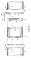
- FIG. 1 parts of preferably a motor-gear unit are shown in an exploded view, which are to be connected moisture-tight.
- a cup-shaped housing (10) with a flange-like edge (12) is designed as a motor housing, for example to accommodate a permanent magnet-excited commutator motor.
- the housing (14) to be connected to the motor housing (10), preferably accommodating a transmission, likewise has a pot shape and is provided with a flange-like edge (16).
- the connection of the housings (10) and (14) can be done via fastening, not shown elements are made by mutual bracing in a manner as can be seen, for example, from EP-A-0 219 681.
- a pot-shaped or cup-shaped support (18) made of plastic is arranged in the motor housing (10), the bottom surface (20) of which supports a grid (22), which is preferably a deep-drawn part. Due to this type of production, a three-dimensional grid is made available which provides a high number and density of conductor tracks.
- the cylindrical wall of the carrier (10) can be double-walled, at least in certain areas, in order to accommodate electrical and electronic components in a positionally precise and tightly packed manner in a manner concentric with a commutator of the electric motor received by the carrier (18) in such a way that a largely automatic assembly takes place, so that automatic production becomes possible.
- a cover part (24) is preferably snapped into place on the front side, preferably by means of locking lugs.
- the cover part (14) is provided with a flat gasket (26), which is either connected to the cover part (24) in a latching manner or is preferably formed integrally with the cover part (24) in a two-component injection molding process.
- the cover part (24) can be a hard plastic part, whereas the seal (26) is in particular a dynamically cross-linked polyolefin elastomer.
- the seal (26) runs between the flange-like edges (12) and (16), thus lies against the respective end faces (28) and (30) and is compressed to a degree when the housings (10) and (14) are clamped, that an adequate seal between the housings (10) and (14) is guaranteed.
- the cover part (24) has, as an integral part, a receptacle (32) for preferably a speed control for the electric motor, in order to be equipped with the appropriate electrical and electronic components or not depending on the application requirements.
- the seal (26) is of sufficient strength. It preferably has a thickness that is 5 to 10 times, preferably 6 to 7 times larger than the diameter of the strongest electrical cable (34).
- the thickness of the disc-shaped flat seal (26) can be 3 to 3.5 mm.
- seal (26) with cover part (24), which is preferably produced in the two-component injection molding process are, for. B. FIGS. 2 and 3. It can be seen that the seal (26) has a peripheral edge (36) which comes to lie between the end faces (28) and (30). From one of the convex narrow sides there is a flag-like or possibly angled, i.e. section L-shaped section (38) running along the outer wall of the housing (10), through which the cables (34) are guided or in which a plug part a plug device runs, as can be seen in particular in FIGS. 9 to 14.
- the section (38) has web-shaped and parallel walls, two of which are provided with the reference numerals (40) and (42) by way of example.
- the cables (34) connected to the motor and its regulating elements are then laid, which are stripped and tinned in the area in which they are to be surrounded by the sealing material.
- the cavities in the section (38) or the passage areas of the seals (26) can be covered and sealed with the sealing material in order to achieve the desired moisture-tight passage of the cables (34 ) through the seal (26) between the end faces (28) and (30).
- the material thickness of the seal (26) can be increased if necessary. This area is indicated in FIG. 2 by cross hatching and provided with the reference symbol (44).
- the cover part (24) has a circular opening (54) which is penetrated by a shaft which projects into the transmission housing (14). Coaxial with the opening (54) is the receptacle for speed control indicated in FIG. 1 by the reference number (32) and in FIG. 3 by the reinforced line (56). As mentioned, the receptacle (32) is preferably produced in an injection molding process together with the cover part (24).
- the openings (60) and (62) indicated by double circles in FIG. 3 preferably run inside the carrier (18) in order to accommodate cables (not shown) which can be connected to the carbon brushes or electrical or electronic components.
- the gap between the cable and the inner wall of the funnel-shaped guides (60) and (62) can be filled with the sealing material if the cables run through the section (38) and the region (44) covered with the material of the seal (26) or the available spaces are filled. This provides an additional cable seal in the area of the carrier (18).
- FIG. 4 This feature can also be seen in FIG. 4.
- the funnel-shaped wall of the guide (60) through which a cable provided with the reference symbol (64) is guided can be seen.
- the space between the inner wall of the guide (60) and the cable (64) is then filled with the material of the seal.
- the guide (60) in the exemplary embodiment according to FIGS. 2 and 3 runs approximately in the area (44) of the seal (26).
- FIG. 5 shows a special embodiment of the seal (26) in the region of its edge (36), that is to say in the region between the end faces (30) and (28) of the flange-like edges (12) and (16) of the Housing (10) and (14) runs.
- the end face (28) has circumferential projections (70) and (72), possibly interrupted in the region of the section (38) of the seal (26), between which a projection extending from the facing surface of the edge (36) of the seal (26) (74) comes to rest.
- the electrical connections to be connected to the motor and the electrical elements are connected to the cables to be supplied from the outside by plug connections.
- the electrical connections within the housing (12) in the region of the seal in particular in the region of the section (38) which is either lug-shaped or outwardly L-shaped, preferably U-shaped mother plug (76), into which tongue-shaped end sections (78) of the cables (34) can be snapped.
- the claw-shaped or U-shaped legs of the nut piece (76) have projections (80) and (82) which snap into corresponding recesses or depressions (84) and (86) of the section (78) so as to establish a secure connection.
- FIG. 8 An alternative embodiment of the nut part running inside the seal (26) can be seen in FIG. 8.
- a claw-like nut part (86) can be seen, into which a tongue-shaped end section of a cable (not shown) can be snapped.
- each leg of the nut piece (86) which is U-shaped in side view, has projections (88), (90) and (92) and (94) which run parallel to one another and face each other in pairs and snap into corresponding recesses or recesses in a tongue-shaped male part of a cable.
- FIGS. 9 to 14 show preferred developments of the seal (26) according to the invention with regard to the current feedthrough, that is to say the electrical connecting cables.
- the identically constructed flat seals (26) have differently shaped outer sections (100), (102) and (104) which function according to the section (38) of Figs. 2 and 3 correspond.
- Sections (100), (102) and (104), however, are designed according to the invention as a plug part of a plug device, the plug part optionally being a plug (FIGS. 9, 10, 13, 14) or a plug receptacle (FIGS. 11 and 12) can be trained.
- This section (100) is produced at the same time as the flat gasket (26) as a unit, so that the contact pins (108) are consequently at least partially encapsulated by the flat gasket material.
- the free ends (110) of the contact pins (108) can now be inserted into a plug receptacle, not shown, in order to establish the required electrical connection.
- the connector receptacle can be pushed onto the section (100) to such an extent that it is watertight. As a result, further sealing measures are generally not required.
- FIGS. 11 and 12 provides a plug receptacle (112) as the plug part, which in the exemplary embodiment has four plug sockets (114) into which plug pins (not shown) can be inserted.
- the section (102) in the region of the plug sockets (114) has circumferential bead-like sections (116) and (118) which can be snapped into corresponding ring-shaped receptacles of the plug part (not shown), so that the to achieve the desired tightness. It is consequently provided by section (102), as by section (100), that a plug adapter is formed integrally with the seal (26) and thus one allows a watertight connection to a plug counterpart, not shown, whereby the type of connection between the plug parts can be done in the usual way.
- the exemplary embodiment in FIGS. 13 and 14 provides a different embodiment of the plug part (104) formed integrally with the flat seal (26).
- the plug part (104) is designed as a plug, from which pin-shaped cable sections (120) protrude like pins that can be inserted into a correspondingly designed plug receptacle.
- the seal With the seal (26) unchanged as the base part and the electrical connection running in it, the seal itself can be formed with plug parts of different plug geometries, in order to establish an electrical connection with correspondingly assigned plug parts in a simple manner, without additional Sealing elements sufficient water resistance is achieved.
Landscapes
- Engineering & Computer Science (AREA)
- Power Engineering (AREA)
- Motor Or Generator Frames (AREA)
- Connector Housings Or Holding Contact Members (AREA)
Applications Claiming Priority (1)
| Application Number | Priority Date | Filing Date | Title |
|---|---|---|---|
| DE3823404A DE3823404C3 (de) | 1988-07-09 | 1988-07-09 | Durchführung für elektrische Kabel |
Publications (1)
| Publication Number | Publication Date |
|---|---|
| EP0432283A1 true EP0432283A1 (de) | 1991-06-19 |
Family
ID=6358398
Family Applications (1)
| Application Number | Title | Priority Date | Filing Date |
|---|---|---|---|
| EP89122739A Withdrawn EP0432283A1 (de) | 1988-07-09 | 1989-12-09 | Durchführung für elektrische Kabel |
Country Status (2)
| Country | Link |
|---|---|
| EP (1) | EP0432283A1 (enExample) |
| DE (1) | DE3823404C3 (enExample) |
Cited By (6)
| Publication number | Priority date | Publication date | Assignee | Title |
|---|---|---|---|---|
| DE4227062C1 (de) * | 1992-08-15 | 1994-03-17 | Steinmueller Kg Atlanta Kabel | Dichtende Anschlußplatte für einen Elektromotor |
| EP0645875A1 (de) * | 1993-09-08 | 1995-03-29 | Siemens Aktiengesellschaft | Motor-Pumpen-Aggregat, insbesondere Kraftfahrzeug-Antiblockier-Bremsvorrichtung |
| DE29702510U1 (de) * | 1997-02-13 | 1998-03-19 | Siemens AG, 80333 München | Elektromotor mit außen am Motorgehäuse angeordnetem Feststecker |
| DE19718161A1 (de) * | 1997-04-29 | 1998-11-12 | Siemens Ag | Elektromotor mit außen am Motorgehäuse angeordnetem Feststecker |
| DE10342219A1 (de) * | 2003-09-11 | 2005-04-21 | K Tec Kunststoffverarbeitung G | Topf- oder becherförmiger Träger |
| CN110545002A (zh) * | 2018-05-28 | 2019-12-06 | 法雷奥电机设备公司 | 带有成角度地楔入的电刷支架垫圈的密封的机动车辆启动器 |
Families Citing this family (10)
| Publication number | Priority date | Publication date | Assignee | Title |
|---|---|---|---|---|
| DE3823404C3 (de) * | 1988-07-09 | 1995-06-29 | Schunk Motorensysteme | Durchführung für elektrische Kabel |
| DE4018846A1 (de) * | 1990-06-13 | 1991-12-19 | Reinshagen Kabelwerk Gmbh | Kohlenbuerstentraeger |
| EP0489940B1 (de) * | 1990-12-07 | 1994-05-18 | Siemens Aktiengesellschaft | Bürstensystem für einen Kommutatormotor |
| US5444315A (en) * | 1992-12-18 | 1995-08-22 | Siemens Aktiengesellschaft | Bushing isolator for lead-through of electrical lines providing moisture sealing between two housings |
| DE4320005C5 (de) * | 1993-06-17 | 2008-03-27 | Continental Teves Ag & Co. Ohg | Elektrische Maschine zur Wandlung von elektrischer und mechanischer Energie, insbesondere radialkraftbeaufschlagter Elektromotor zum Antrieb von Pumpen |
| EP0735643B1 (de) * | 1994-12-09 | 1997-06-11 | Siemens Aktiengesellschaft | Abgedichtete Verbindungsvorrichtung zwischen zwei Gehäuse-Stirnseiten |
| DE10321179A1 (de) * | 2003-05-12 | 2004-12-02 | Volkswagen Ag | Elektrisch angetriebener Taumelscheibenkompressor |
| DE102010028336A1 (de) * | 2010-04-28 | 2011-11-03 | Robert Bosch Gmbh | Elektromotor mit einer in einem Motorgehäuse eingeschlossenen Steuereinheit |
| DE102013001872B4 (de) | 2013-02-02 | 2021-07-22 | Audi Ag | Kraftwagen mit einem Aggregat zum Antreiben des Kraftwagens |
| DE102014109416A1 (de) * | 2014-07-04 | 2016-01-07 | Ims Gear Gmbh | Motor-Getriebe-Verbindung mittels Klebeband |
Citations (6)
| Publication number | Priority date | Publication date | Assignee | Title |
|---|---|---|---|---|
| FR1551840A (enExample) * | 1968-01-26 | 1968-12-27 | ||
| EP0213863A2 (en) * | 1985-08-27 | 1987-03-11 | The Superior Electric Company | Programmable electrical connector |
| EP0219681A1 (de) * | 1985-09-26 | 1987-04-29 | Siemens Aktiengesellschaft | Geschlossene Motor-Getriebe-Einheit |
| DE8908892U1 (de) * | 1988-07-26 | 1989-09-28 | Atlanta-Kabel-Steinmüller KG, 5880 Lüdenscheid | Anschlußdichtung für einen Elektromotor |
| DE3810960A1 (de) * | 1988-03-31 | 1989-10-19 | Schunk Motorensysteme | Durchfuehrung fuer elektrische kabel |
| DE3823404A1 (de) * | 1988-07-09 | 1990-01-11 | Schunk Motorensysteme | Durchfuehrung fuer elektrische kabel |
Family Cites Families (3)
| Publication number | Priority date | Publication date | Assignee | Title |
|---|---|---|---|---|
| FR2402964A1 (fr) * | 1977-09-13 | 1979-04-06 | Paris & Du Rhone | Moteur electrique |
| JPS60186852U (ja) * | 1984-05-17 | 1985-12-11 | 三菱電機株式会社 | 電動機の防水装置 |
| DE3804677A1 (de) * | 1988-02-15 | 1989-08-24 | Steinmueller Kg Atlanta Kabel | Dichtende anschlussanordnung fuer einen elektromotor |
-
1988
- 1988-07-09 DE DE3823404A patent/DE3823404C3/de not_active Expired - Fee Related
-
1989
- 1989-12-09 EP EP89122739A patent/EP0432283A1/de not_active Withdrawn
Patent Citations (6)
| Publication number | Priority date | Publication date | Assignee | Title |
|---|---|---|---|---|
| FR1551840A (enExample) * | 1968-01-26 | 1968-12-27 | ||
| EP0213863A2 (en) * | 1985-08-27 | 1987-03-11 | The Superior Electric Company | Programmable electrical connector |
| EP0219681A1 (de) * | 1985-09-26 | 1987-04-29 | Siemens Aktiengesellschaft | Geschlossene Motor-Getriebe-Einheit |
| DE3810960A1 (de) * | 1988-03-31 | 1989-10-19 | Schunk Motorensysteme | Durchfuehrung fuer elektrische kabel |
| DE3823404A1 (de) * | 1988-07-09 | 1990-01-11 | Schunk Motorensysteme | Durchfuehrung fuer elektrische kabel |
| DE8908892U1 (de) * | 1988-07-26 | 1989-09-28 | Atlanta-Kabel-Steinmüller KG, 5880 Lüdenscheid | Anschlußdichtung für einen Elektromotor |
Cited By (10)
| Publication number | Priority date | Publication date | Assignee | Title |
|---|---|---|---|---|
| DE4227062C1 (de) * | 1992-08-15 | 1994-03-17 | Steinmueller Kg Atlanta Kabel | Dichtende Anschlußplatte für einen Elektromotor |
| EP0645875A1 (de) * | 1993-09-08 | 1995-03-29 | Siemens Aktiengesellschaft | Motor-Pumpen-Aggregat, insbesondere Kraftfahrzeug-Antiblockier-Bremsvorrichtung |
| US6208048B1 (en) | 1993-09-08 | 2001-03-27 | Siemens Aktiengesellschaft | Motor-pump unit, particularly motor vehicle anti-lock brake device having internal electrical connecting lines |
| DE29702510U1 (de) * | 1997-02-13 | 1998-03-19 | Siemens AG, 80333 München | Elektromotor mit außen am Motorgehäuse angeordnetem Feststecker |
| DE19718161A1 (de) * | 1997-04-29 | 1998-11-12 | Siemens Ag | Elektromotor mit außen am Motorgehäuse angeordnetem Feststecker |
| DE19718161B4 (de) * | 1997-04-29 | 2004-09-30 | Siemens Ag | Elektromotor mit außen am Motorgehäuse angeordnetem Feststecker |
| DE10342219A1 (de) * | 2003-09-11 | 2005-04-21 | K Tec Kunststoffverarbeitung G | Topf- oder becherförmiger Träger |
| US7176591B2 (en) | 2003-09-11 | 2007-02-13 | K-Tec Kunststoffverarbeitung Gmbh | Pot-like or cup-like carrier |
| CN110545002A (zh) * | 2018-05-28 | 2019-12-06 | 法雷奥电机设备公司 | 带有成角度地楔入的电刷支架垫圈的密封的机动车辆启动器 |
| CN110545002B (zh) * | 2018-05-28 | 2021-07-23 | 法雷奥电机设备公司 | 带有成角度地楔入的电刷支架垫圈的密封的机动车辆启动器 |
Also Published As
| Publication number | Publication date |
|---|---|
| DE3823404C2 (enExample) | 1990-08-23 |
| DE3823404C3 (de) | 1995-06-29 |
| DE3823404A1 (de) | 1990-01-11 |
Similar Documents
| Publication | Publication Date | Title |
|---|---|---|
| EP0432283A1 (de) | Durchführung für elektrische Kabel | |
| DE102010052728B4 (de) | Teilvergossenes Netzteil und Herstellungsverfahren | |
| EP0335352B1 (de) | Becherförmiger Träger bestimmt für einen Elektromotor | |
| EP2043234B1 (de) | Elektromotor | |
| DE10029449B4 (de) | Wasserdichtes Steckverbindungselement | |
| DE10041837B4 (de) | Wasserdichter Stecker | |
| DE19851455A1 (de) | Elektronikmodul für eine elektromotorisch betriebene Antriebseinheit | |
| WO1999040285A1 (de) | Elektronikmodul für eine elektromotorisch betriebene antriebseinheit | |
| DE69601008T2 (de) | Abgedichtete elektrische Verbinderanordnung | |
| DE102013112096B4 (de) | Funktionskomponentengehäuse mit einer Dichtung, Funktionskomponentengehäusebausatz mit einer Dichtung und Dichtung | |
| EP3878056A1 (de) | Kontaktelement zur elektrischen kontaktierung eines elektrischen leiters an ein anschlussteil einer elektrischen anlage und verfahren zu dessen herstellung | |
| EP1088374B1 (de) | Durchführungsadapter für schaltschränke | |
| WO2020229228A1 (de) | Getriebeeinheit sowie montage einer getriebeeinheit mit klemmenblock | |
| DE4128928A1 (de) | Verbindungseinheit fuer entladungslampe | |
| EP2690412A9 (de) | Sensor | |
| WO2002047212A1 (de) | Mehrpoliger steckverbinder | |
| DE19816216C2 (de) | Elektrischer Stecker und Steckverbindung | |
| DE102014215231B4 (de) | Getriebe-Antriebseinheit einschiebbaren Elektronikmodul | |
| WO2004055947A1 (de) | Elektrischer verbinder | |
| DE4224155C2 (de) | Elektrische Steckverbinderanordnung | |
| DE4224154C1 (de) | Wasserdichte elektrische Steckverbinderanordnung | |
| DE9116586U1 (de) | Durchführung für elektrische Leitungen | |
| DE3810960C2 (enExample) | ||
| DE10161102A1 (de) | Leitungs-Steckverbindung für elektrisches Steuergerät sowie Herstellungsverfahren | |
| DE102012102849A1 (de) | Befestigung und Abdichtung eines Steckanschlussmoduls in einer Gehäusewandung |
Legal Events
| Date | Code | Title | Description |
|---|---|---|---|
| PUAI | Public reference made under article 153(3) epc to a published international application that has entered the european phase |
Free format text: ORIGINAL CODE: 0009012 |
|
| 17P | Request for examination filed |
Effective date: 19910102 |
|
| AK | Designated contracting states |
Kind code of ref document: A1 Designated state(s): AT BE CH DE ES FR GB GR IT LI LU NL SE |
|
| RBV | Designated contracting states (corrected) |
Designated state(s): DE ES FR GB IT |
|
| STAA | Information on the status of an ep patent application or granted ep patent |
Free format text: STATUS: THE APPLICATION HAS BEEN WITHDRAWN |
|
| 18W | Application withdrawn |
Withdrawal date: 19920702 |