EP2690412A9 - Sensor - Google Patents
Sensor Download PDFInfo
- Publication number
- EP2690412A9 EP2690412A9 EP12177898.9A EP12177898A EP2690412A9 EP 2690412 A9 EP2690412 A9 EP 2690412A9 EP 12177898 A EP12177898 A EP 12177898A EP 2690412 A9 EP2690412 A9 EP 2690412A9
- Authority
- EP
- European Patent Office
- Prior art keywords
- housing
- circuit board
- sensor
- printed circuit
- sensor element
- Prior art date
- Legal status (The legal status is an assumption and is not a legal conclusion. Google has not performed a legal analysis and makes no representation as to the accuracy of the status listed.)
- Granted
Links
- 238000004519 manufacturing process Methods 0.000 claims abstract description 10
- 150000001875 compounds Chemical class 0.000 claims description 42
- 238000004382 potting Methods 0.000 claims description 39
- 238000005266 casting Methods 0.000 claims description 28
- 229910052751 metal Inorganic materials 0.000 claims description 14
- 239000002184 metal Substances 0.000 claims description 14
- 238000000034 method Methods 0.000 claims description 6
- 229910000679 solder Inorganic materials 0.000 claims description 4
- 239000013307 optical fiber Substances 0.000 claims 1
- 239000004033 plastic Substances 0.000 description 12
- 238000003825 pressing Methods 0.000 description 9
- 230000001939 inductive effect Effects 0.000 description 6
- 239000000853 adhesive Substances 0.000 description 4
- 230000001070 adhesive effect Effects 0.000 description 4
- 230000003287 optical effect Effects 0.000 description 4
- HCHKCACWOHOZIP-UHFFFAOYSA-N Zinc Chemical compound [Zn] HCHKCACWOHOZIP-UHFFFAOYSA-N 0.000 description 3
- 238000004512 die casting Methods 0.000 description 3
- 230000007613 environmental effect Effects 0.000 description 3
- 238000005476 soldering Methods 0.000 description 3
- 229910052725 zinc Inorganic materials 0.000 description 3
- 239000011701 zinc Substances 0.000 description 3
- PXHVJJICTQNCMI-UHFFFAOYSA-N Nickel Chemical compound [Ni] PXHVJJICTQNCMI-UHFFFAOYSA-N 0.000 description 2
- 229910001297 Zn alloy Inorganic materials 0.000 description 2
- 239000004020 conductor Substances 0.000 description 2
- 238000001746 injection moulding Methods 0.000 description 2
- 239000007788 liquid Substances 0.000 description 2
- 238000003754 machining Methods 0.000 description 2
- 239000012778 molding material Substances 0.000 description 2
- 238000009757 thermoplastic moulding Methods 0.000 description 2
- 238000010136 thermoset moulding Methods 0.000 description 2
- 230000015572 biosynthetic process Effects 0.000 description 1
- 230000000295 complement effect Effects 0.000 description 1
- 238000001514 detection method Methods 0.000 description 1
- 238000009713 electroplating Methods 0.000 description 1
- 238000002347 injection Methods 0.000 description 1
- 239000007924 injection Substances 0.000 description 1
- 238000003780 insertion Methods 0.000 description 1
- 230000037431 insertion Effects 0.000 description 1
- 230000013011 mating Effects 0.000 description 1
- 238000000465 moulding Methods 0.000 description 1
- 229910052759 nickel Inorganic materials 0.000 description 1
- 239000011347 resin Substances 0.000 description 1
- 229920005989 resin Polymers 0.000 description 1
- 239000000126 substance Substances 0.000 description 1
- 229920001169 thermoplastic Polymers 0.000 description 1
- 239000012815 thermoplastic material Substances 0.000 description 1
- 239000004416 thermosoftening plastic Substances 0.000 description 1
Images

Classifications
-
- G—PHYSICS
- G01—MEASURING; TESTING
- G01D—MEASURING NOT SPECIALLY ADAPTED FOR A SPECIFIC VARIABLE; ARRANGEMENTS FOR MEASURING TWO OR MORE VARIABLES NOT COVERED IN A SINGLE OTHER SUBCLASS; TARIFF METERING APPARATUS; MEASURING OR TESTING NOT OTHERWISE PROVIDED FOR
- G01D11/00—Component parts of measuring arrangements not specially adapted for a specific variable
- G01D11/24—Housings ; Casings for instruments
- G01D11/245—Housings for sensors
-
- H—ELECTRICITY
- H03—ELECTRONIC CIRCUITRY
- H03K—PULSE TECHNIQUE
- H03K17/00—Electronic switching or gating, i.e. not by contact-making and –breaking
- H03K17/94—Electronic switching or gating, i.e. not by contact-making and –breaking characterised by the way in which the control signals are generated
- H03K17/945—Proximity switches
- H03K17/955—Proximity switches using a capacitive detector
-
- H—ELECTRICITY
- H03—ELECTRONIC CIRCUITRY
- H03K—PULSE TECHNIQUE
- H03K2217/00—Indexing scheme related to electronic switching or gating, i.e. not by contact-making or -breaking covered by H03K17/00
- H03K2217/94—Indexing scheme related to electronic switching or gating, i.e. not by contact-making or -breaking covered by H03K17/00 characterised by the way in which the control signal is generated
- H03K2217/96—Touch switches
- H03K2217/9607—Capacitive touch switches
- H03K2217/960755—Constructional details of capacitive touch and proximity switches
-
- Y—GENERAL TAGGING OF NEW TECHNOLOGICAL DEVELOPMENTS; GENERAL TAGGING OF CROSS-SECTIONAL TECHNOLOGIES SPANNING OVER SEVERAL SECTIONS OF THE IPC; TECHNICAL SUBJECTS COVERED BY FORMER USPC CROSS-REFERENCE ART COLLECTIONS [XRACs] AND DIGESTS
- Y10—TECHNICAL SUBJECTS COVERED BY FORMER USPC
- Y10T—TECHNICAL SUBJECTS COVERED BY FORMER US CLASSIFICATION
- Y10T29/00—Metal working
- Y10T29/49—Method of mechanical manufacture
- Y10T29/49002—Electrical device making
- Y10T29/49117—Conductor or circuit manufacturing
- Y10T29/49124—On flat or curved insulated base, e.g., printed circuit, etc.
- Y10T29/49128—Assembling formed circuit to base
Definitions
- the present invention relates to a sensor according to claim 1 and a method for producing a sensor according to the preamble of claim 14.
- Sensors for example optical, inductive or capacitive sensors, are used in various technical applications for the detection of physical or chemical parameters.
- the housing serves to protect electronic components on a printed circuit board and a sensor element from damaging environmental influences.
- the electronic components inside the housing are to be supplied with electric current. For this reason, it is necessary to guide electrical contacts through a housing wall of the housing in order to be able to supply the sensor from the outside with electrical current at an outer part of the contact parts.
- the circuit board with the electronic components and the sensor element are usually enveloped by a potting compound.
- the potting compound serves, on the one hand, to fix the printed circuit board and the sensor element in a positive and cohesive manner and, on the other hand, to keep out damaging environmental influences, for example liquids, from the printed circuit board and the sensor element.
- This is a fluid-tight sensor.
- the printed circuit board Before casting the sensor with the potting compound, it is necessary to connect the circuit board and the sensor element with the housing directly or indirectly for positioning the circuit board and / or the sensor element during the potting of the housing interior with potting compound.
- the printed circuit board Before casting with casting compound, the printed circuit board is generally connected to the electrical contacts of the sensor, generally by means of soldering. In an adhesive bond between the Printed circuit board and / or the sensor element and the housing before potting with potting compound, this adhesive connection is complicated and expensive to manufacture and has low flexibility for different types of sensors.
- the DE 195 44 815 C1 shows a sensor with a carrier disposed on an electrical circuit, which is connected to an electrical connection element and with a sensor element. Furthermore, a housing with an interior for receiving the carrier is shown, which in each case has an opening for the connection element and for the sensor element. In this case, the sensor element and a first part of the carrier are embedded in a thermoset molding compound. A second part of the carrier and the electrical connection element are enclosed by a thermoplastic molding compound. In a gap, adjacent to the opening for the sensor element, between the thermoset molding compound and the housing, a seal is arranged.
- the DE 100 13 218 C2 shows a method for producing a position sensor with a housing in the housing interior an electrical circuit arranged on a support sits, comprising the steps: the carrier is connected to a plug insert as an electrical connection element to a carrier-connection element combination, wherein the connection element rigidly with connected to the carrier, the carrier-connection element combination is introduced into the housing closed at a measuring end from a rear end opposite the measuring end, the space around the carrier-connection element combination in the housing interior is filled to a certain level with a molding compound, with the rear end of the housing, a cap is connected before curing of the molding material, through which the terminals of the connection element are guided, and with which the carrier-connection element combination is fixed in the housing.
- the object of the present invention is to provide a sensor and a method for producing a sensor, in which a printed circuit board and / or a sensor element with a low technical complexity can be reliably attached to the housing prior to casting with potting compound.
- a sensor comprising at least one housing, which encloses a housing interior, a printed circuit board with electronic components, which is arranged within the housing interior, a sensor element, which is electrically connected to the circuit board and is disposed within the housing interior, wherein the sensor element positively connected to the housing, so that the sensor element is held in the housing interior in position.
- the sensor element can thus first be fixed simply and inexpensively to the housing by means of a frictional connection, in particular a latching, click or press connection. Subsequently, a casting of the housing interior with a potting compound, for example, a thermoplastic molding material or a casting resin, take place.
- a frictional connection in particular a latching, click or press connection.
- the circuit board is non-positively connected to the housing.
- the printed circuit board and the sensor element can be exclusively positively connected to the housing, in particular apart from the cohesive connection due to the potting compound and / or apart from a mechanical connection to, in particular exclusive, electrical connection of the circuit board and / or the sensor element.
- the housing is preferably designed as a housing pot and substantially cuboid.
- the housing consists at least partially, in particular completely, of metal and / or plastic.
- the housing can be made in several parts.
- the housing may be in the area of Sensor element may be formed as a translucent or opaque cap.
- the cap made of plastic and the rest of the housing are made of metal.
- the sensor may be an optical, inductive or capacitive sensor.
- the housing also has a housing cover.
- the printed circuit board comprises printed conductors and the electronic components are electrically and mechanically connected to the printed circuit board.
- the circuit board is disposed entirely within the housing interior enclosed by the housing.
- the circuit board and / or the sensor element can be completely enclosed by the potting compound. As a result, no damaging environmental influences, for example a liquid, can reach the printed circuit board and / or the sensor element. It is in this case a liquid- or fluid-tight sensor, which is particularly splash-proof.
- At least one positive locking geometry is formed on the housing and at least one counter-form-locking geometry is formed on the printed circuit board, with the at least one form-fitting and counter-form-fitting geometry frictionally engaging with one another for connecting the printed circuit board to the housing.
- the positive locking geometry is preferably designed as a connecting cam and / or a locking shoulder.
- As Gegenform gleichgeometrie an opening and / or a latch can be formed.
- a frictional connection is preferably carried out due to a press connection of form-locking geometry and counter-form-fitting geometry.
- the present inventive sensor is at the at least one GegenformQuerygeometrie ever an electrical circuit board contact element for electrically conductive connection of the circuit board to the housing on the formed at least one form fit geometry. This can additionally be made available between the circuit board and the housing an electrically conductive connection.
- the ever an electrical circuit board contact element can be designed here as a metal ring. If the housing consists at least partially, in particular completely, of metal, cable-bound radio-frequency interference can be conducted from the printed circuit board to the housing in an advantageous manner.
- this electrical connection between the circuit board and the housing is particularly reliable, because due to the non-positive connection, for example a press connection, constantly a mechanical and thus an electrical contact between the Printed circuit board contact element on the Gegenform gleichgeometrie and the positive locking geometry, for example, the connecting cam exists.
- the sensor element is a coil and the sensor is an inductive proximity sensor or the sensor element is an LED and / or a phototransistor and the sensor is an optical sensor.
- the housing is transparent to the LED and / or phototransistor.
- the senor element is held elastically biased by means of an elastic element between the housing and the elastic element.
- the elastic element may in this case be designed as a spring.
- the sensor element is located on a first end directly or indirectly on the housing, in particular the cap, and due to the geometry of the housing, for example as a recess, the sensor element is positively held on the housing.
- the elastic element can also rest on a second end directly or indirectly on the sensor element.
- the first and second ends may be opposite to one another Be formed sensor element.
- the sensor element may comprise two sensor element contact elements for electrical connection of the sensor element.
- the sensor element contact elements can also be materially connected, for example with a solder connection, to the printed circuit board, in particular printed circuit board contact elements, electrically connected.
- the sensor element for example, indirectly connected to a plug-in part frictionally under elastic bias to the elastic element.
- a resilient bias of the elastic member is for example possible because due to a non-positive connection, in particular a press connection between the form and Gegenform gleichgeometrie forces from the elastic element on the circuit board and from the circuit board to the housing can be transferred.
- the housing has a plug opening, with which a plug sleeve is in particular non-positively connected.
- the frictional connection can be effected by means of a press connection.
- a plug part for example made of plastic, arranged with electrical contact elements as electrical contacts.
- the plug sleeve can be made of metal.
- a cable seal made of plastic can be provided at the plug opening, are guided by the electric power cable as electrical contacts.
- the sensor expediently comprises a light guide and a light transmitter, for example an LED, so that the light generated by the light transmitter outside the sensor can be conducted from the light transmitter through the light guide.
- the light guide is arranged on the outside on two or three sides of the sensor, so that the light emitted by the light emitter light is visible on two or three sides of the sensor.
- a frictional connection which serves to electrically connect the circuit board and / or the sensor element, for example with the contacts for the electrical supply of the sensor, is not taken into consideration.
- mechanical connection to the electrical connection also constitute mechanical connections, they can provide no or substantially no contribution to a sufficient mechanical attachment or positioning of the printed circuit board and / or the sensor element before casting with the potting compound due to their mechanical properties.
- the housing can be injection molded, for.
- As plastic in particular thermoplastic, or metal, eg. As zinc or a zinc alloy, provided and preferably the housing is coated after injection molding, in particular by means of electroplating, z. As with metal, especially nickel.
- the housing is expediently made available as a housing pot and / or the housing is provided with a cap opening and / or the housing is provided with a plug opening; in particular, at least one pressing shoulder, preferably two pressing shoulders, is formed on the plug opening.
- the cap opening can be closed with a cap, in particular the cap positively and / or non-positively, for example with a latching connection, is connected to the housing, in particular before casting with potting compound.
- a plug sleeve can further be inserted, wherein the plug sleeve is connected to the housing at the plug opening with a positive and / or non-positive connection, in particular a press connection, so that in particular at least one counterpressive shoulder, preferably at least two counterpressive heels on the Plug sleeve on the at least one pressing paragraph, preferably two pressing paragraphs, rest on the plug opening of the housing, in particular before casting with potting compound.
- a cable seal can be inserted and positively and / or positively and / or materially connected to the housing at the plug opening, in particular before casting with potting compound. Due to the Pressabsatzes on the housing and the Gegenpressabsatzes on the plug sleeve, preferably made of metal, thereby a sufficient press connection can be made available and produced at a small housing wall thickness at the plug opening.
- the press sales and the counter press sales thus an additional pressing surface in addition to the normal press opening at the plug opening of the corresponding housing wall, for example, rear wall of the housing available.
- a plug part, z. B. plastic introduced with the electrical contact elements as contacts and positively and / or positively and / or materially connected to the plug sleeve, in particular after connecting the plug sleeve to the housing at the plug opening, in particular before casting with potting compound.
- power cables can be routed through a cable opening, in particular after connecting the cable seal to the housing at the plug opening, in particular before casting with potting compound.
- the sensor element is connected to the housing by the sensor element between the housing, in particular the cap, and an elastic member, in particular a spring, is elastically biased, in particular before casting with potting compound, and / or the circuit board on at least one housing paragraph, in particular at least two housing heels, placed, in particular before casting with potting compound, and / or the circuit board is positively connected to at least one form fit geometry of at least one GegenformQuerygeometrie on the housing, in particular at least one connecting cam, preferably two connecting cams on the Housing in at least one opening, in particular two openings are introduced on the circuit board, in particular before casting with potting compound.
- the at least one interlocking geometry on the printed circuit board is additionally frictionally connected to the at least one counterframe geometry on the printed circuit board, in particular by at least one connecting cam being pressed against the housing with the printed circuit board at the opening, in particular before casting with potting compound, and / or the elastic element is cohesively, for example by means of soldering, connected to the circuit board and / or sensor element contact elements on the sensor element are electrically connected to the printed circuit board, in particular by soldering the sensor element contact elements with printed circuit board contact elements, in particular before casting with potting compound, and / or the electrical contacts are electrically connected to the circuit board, in particular soldered by the contacts with PCB contact elements be, especially before casting with potting compound.
- a light guide in particular before casting with potting compound, non-positively connected to the housing, for example with a latching connection, in particular before casting with potting compound.
- the housing pot comprises only one opening for insertion of the printed circuit board.
- the senor is fluid-tight, in particular the printed circuit board with electronic components and / or the sensor element are enveloped or embedded in a fluid-tight manner by the potting compound.
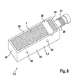
- An in Fig. 7 and 8th illustrated sensor 1 is designed as an inductive sensor 2 and thus represents a proximity sensor. With the inductive sensor 2 objects can be detected in the area or in the vicinity thereof.
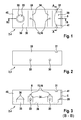
- the sensor 1,2 comprises a housing 3, which is designed as a housing pot 4 (shown in FIG Figure 3 ).
- the housing 3 is made of metal, namely a zinc alloy, and is manufactured by means of a zinc die casting process.
- the housing pot 4 ( Fig. 1 to 4 ) includes a housing interior 6.
- the housing interior 6 is bounded by a bottom wall 38, two side walls 39, a front wall 40 and a rear wall 41 of the housing pot 4.
- On the bottom wall 38 two housing heels 34 are formed in the transverse direction.
- a connecting cam 16 is designed as a positive locking geometry 15 for supporting a printed circuit board 8 in each case.
- a mounting hole 30 is provided in each case in the transverse direction.
- the mounting holes 30 preferably have a thread.
- the bottom wall 38 further includes a cap opening 35.
- the housing 3 has a cap ring 36.
- a plug opening 5 on the rear wall 41 serves to introduce a plug sleeve 26.
- a pressing shoulder 29 is formed on the housing 3 in the region of the plug opening 5 at the bottom. The press shoulder 29 serves to produce an additional pressing surface between the housing 3 and the plug sleeve 26 in a production and connection of the plug sleeve 26 with the housing 3 at the plug opening 5.
- the two side walls 39 have at the top two housing recesses 31 for a light guide 28.
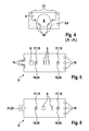
- the printed circuit board 8 On the printed circuit board 8 ( FIGS. 5 and 6 ), four electronic components 9, for example a controller and an electrical resistor, are mechanically and electrically connected to the printed circuit board 8 on the upper side.
- the printed circuit board 8 has printed conductors, not shown for this purpose.
- At the bottom of the printed circuit board 8 ( Fig. 6 ) are two electronic components 9 to the circuit board 8 mechanically and electrically connected.
- the printed circuit board 8 made of plastic has two openings 18 which form a Gegenform gleichgeometrie 17.
- additional metal rings 20 are arranged as printed circuit board contact elements 19 at these openings 18 of the printed circuit board 8.
- the metal rings 20 are electrically conductively connected to the respective connection cam 16. This can be derived via the housing 3 in an advantageous manner interference voltages.
- a spring 22 is attached as an elastic element 21 on the underside of the printed circuit board 8.
- the attachment is realized in this embodiment by means of a solder joint.
- the circuit board 8 also has at the top, as shown in FIG. 5 right, three PCB contact elements 19 on.
- the three printed circuit board contact elements 19 are U-shaped in cross-section ( Fig. 7 ) and thus also on the underside and thus also in Fig. 6 visible, noticeable.
- the geometry of the housing pot 4 described above for example with the housing heels 34 and the cap opening 35 with the cap ring 36, can already be easily produced in the die-casting process, without subsequent machining, for example by machining , is required.
- a cap 14 made of plastic is inserted and pressed into the cap opening 35 on the bottom wall 38 of the housing 3, so that a positive and / or non-positive connection between the cap 14 and the cap ring 36 is made on the housing 3.
- the cap ring 36 provides a relatively large connection area between the cap 14 and the housing 3, that is, the cap ring 36 available.
- the plug sleeve 26 is inserted from metal into the plug opening 5 on the rear wall 41 and pressed, so that a press connection between the plug sleeve 26 and the housing 3 is made. Due to the pressing paragraph 29 on the housing 3 and a counter-pressing shoulder on the plug sleeve 26 is a large press-bonding surface between the plug sleeve 26 and the housing 3 is available. As a result, the thickness of the rear wall 41 has the same thickness as the other walls of the housing 3.
- a plug part 27 made of plastic is inserted into the plug sleeve 26.
- the plug part 27 is made of thermoplastic material by means of injection molding. In this case, three electrical contact elements 13 are encapsulated as electrical contacts 12 of the plastic of the connector part 27.
- the electrical contact elements 13 serve to electrically connect the sensor 1 to the environment.
- three electrical contact elements 13 are integrated into the plug part 27, of which, however, due to the sectional formation in Fig. 7 only an electrical contact element 13 is shown.
- the electrical contact elements 13 are on the in Fig. 7 arranged right end outside of the sensor 1 and can thereby be mechanically and electrically connected to corresponding electrical contact counter-elements (not shown).
- a corresponding electrical mating connector (not shown) on an external thread 37 of the connector sleeve 26 screwed.
- the electrical contact counter-elements can be connected to the electrical contact elements 13.
- the plug part 27 is positively and / or non-positively connected, for example by means of a latching connection, with the plug sleeve 26.
- a coil 11 is placed as a sensor element 10 for the inductive sensor 2 on the cap 14.
- the sensor element 10 can be designed as an LED and / or a phototransistor.
- the cap 14 in this case has a corresponding geometry, so that on the cap 14 on the inside a recess 23 is formed which is complementary to the geometry of the coil 11 is formed. Thus, the coil 11 is held positively in the recess 23 of the cap 14.
- the circuit board 8 is placed on the housing 3 by first the two connecting cam 16 is inserted into the two openings 18 of the circuit board 8 and then the circuit board 8 is placed on the two housing sections 34. This results in a positive connection between the circuit board 8 and the housing 3 to the connection cam 16 and the housing paragraphs 34. In addition, a press connection between the connection cam 16 and the opening 18 on the circuit board 8 is still made by means of a corresponding tool.
- the openings 18 each have metal rings 20 on the printed circuit board 8. This results in a frictional connection between the housing 3 and the circuit board. 8
- the coil 11 is placed on the cap 14.
- An intermediate part 24 in turn is for fitting to a second end 33, the upper end of the coil 11, as shown in FIG Fig. 7 , intended.
- the intermediate part 24 is made of plastic.
- the coil 11 For electrically connecting the coil 11 to the printed circuit board 8, the coil 11 has two contact elements 25 for connecting the coil 11, which in Fig. 7 are shown in dashed lines. These two contact elements 25 for connecting the coil 11 are then connected to the two in Fig. 5 soldered on the left shown PCB contact elements 19, so that thereby the coil 11 is electrically and slightly mechanically connected to the circuit board 8 and the printed circuit board contact elements 19.
- a light guide 28 made of a light-conducting plastic with the two housing recesses 31 on the two side walls 39 is further connected on the upper side, for example by means of a clip or locking connection.
- the housing interior 6 is poured with the potting compound 7, so that thereby the circuit board 8 and the coil 11 are completely enclosed by the potting compound 7.
- the sensor 1 constitutes a fluid-tight sensor 1.
- a cable seal is arranged in the plug opening 5 instead of the plug sleeve 26 and the plug part 27.
- the cable seal is designed as a socket with a cable opening and through this cable opening three power cables can be performed as electrical contacts 12. These power cables are at one end with the three in FIGS. 5 and 6 soldered on the right printed circuit board contact elements 19. At the right ends of the power cables they can be connected for example by means of an electrical screw with a corresponding unit outside the sensor 1.
- the gap or space between the cable opening and the power cables is sealed during pouring with the potting compound 7 and closed.
- the flowability or toughness of the potting compound 7 before hardening is designed so that no or substantially no potting compound 7 passes from these residual openings through the cable opening.
- the circuit board 8 and the coil 11 are positively or non-positively connected directly or indirectly with the housing 3 before casting with the potting compound 7. Thereby, the circuit board 8 and the coil 11 can be easily and inexpensively held before casting with the potting compound 7 on the housing 3 and thus positioned in the housing interior 6. Elaborate adhesive bonds before casting with the potting compound 7 between the circuit board 8 and / or the coil 11 are not required. In addition, advantageously different sensors 1 can be produced in a flexible manner with the same production method.
Abstract
wobei das Sensorelement kraftschlüssig mit dem Gehäuse verbunden ist, so dass das Sensorelement im Gehäuseinnenraum in Position gehalten ist. Verfahren zur Herstellung eines Sensors.
Description
- Die vorliegende Erfindung betrifft einen Sensor gemäß Anspruch 1 und ein Verfahren zur Herstellung eines Sensors gemäß dem Oberbegriff des Anspruches 14.
- Sensoren, zum Beispiel optische, induktive oder kapazitive Sensoren, werden in den verschiedensten technischen Anwendungen zur Erfassung von physikalischen oder chemischen Parametern eingesetzt. Das Gehäuse dient dazu, um Elektronikkomponenten auf einer Leiterplatte sowie ein Sensorelement vor schädigenden Umwelteinflüssen zu schützen. Die Elektronikkomponenten innerhalb des Gehäuses sind dabei mit elektrischem Strom zu versorgen. Aus diesem Grund ist es erforderlich, elektrische Kontakte durch eine Gehäusewandung des Gehäuses zu führen, um an einem äußeren Teil der Kontakteile den Sensor von außen mit elektrischem Strom versorgen zu können.
- Bei einer fluiddichten Ausführung der Sensoren werden die Leiterplatte mit den Elektronikkomponenten und das Sensorelement in der Regel von einer Vergussmasse umhüllt. Die Vergussmasse dient dazu, einerseits die Leiterplatte und das Sensorelement form- und stoffschlüssig zu fixieren und andererseits schädigende Umwelteinflüsse, zum Beispiel Flüssigkeiten, von der Leiterplatte und dem Sensorelement fernzuhalten. Dadurch handelt es sich um einen fluiddichten Sensor. Vor dem Vergießen des Sensors mit der Vergussmasse ist es dabei erforderlich, die Leiterplatte und das Sensorelement mit dem Gehäuse mittelbar oder unmittelbar zur Positionierung der Leiterplatte und/oder des Sensorelements während des Vergießens des Gehäuseinnenraumes mit Vergussmasse zu verbinden. Vor dem Vergießen mit Vergussmasse wird dabei im Allgemeinen auch die Leiterplatte mit den elektrischen Kontakten des Sensors verbunden, im Allgemeinen mittels Löten. Bei einer Klebeverbindung zwischen der Leiterplatte und/oder dem Sensorelement sowie dem Gehäuse vor dem Vergießen mit Vergussmasse ist diese Klebeverbindung in der Herstellung aufwendig und teuer und weist eine geringe Flexibilität für unterschiedliche Arten von Sensoren auf.
- Die
DE 195 44 815 C1 zeigt einen Sensor mit einer auf einem Träger angeordneten elektrischen Schaltung, welche mit einem elektrischen Anschlusselement und mit einem Sensorelement verbunden ist. Ferner ist ein Gehäuse mit einem Innenraum zur Aufnahme des Trägers dargestellt, welches jeweils eine Öffnung für das Anschlusselement sowie für das Sensorelement aufweist. Dabei sind das Sensorelement und ein erster Teil des Trägers in eine Duroplast-Formmasse eingebettet. Ein zweiter Teil des Trägers und das elektrische Anschlusselement sind von einer Thermoplast-Formmasse umschlossen. In einem Zwischenraum, benachbart zu der Öffnung für das Sensorelement, zwischen der Duroplast-Formmasse und dem Gehäuse ist eine Dichtung angeordnet. - Die
DE 100 13 218 C2 zeigt ein Verfahren zur Herstellung eines Positionssensors mit einem Gehäuse in dessen Gehäuseinnenraum ein auf einem Träger angeordneter elektrischer Schaltkreis sitzt, umfassend die Schritte: der Träger wird mit einem Steckereinsatz als elektrischem Anschlusselement zu einer Träger-Anschlusselement-Kombination verbunden, bei der das Anschlusselement starr mit dem Träger verbunden ist,
die Träger-Anschlusselement-Kombination wird in das an einem Messende geschlossene Gehäuse von einem dem Messende gegenüberliegenden Hinterende her eingeführt, der Raum um die Träger-Anschlusselement-Kombination im Gehäuseinnenraum wird bis zu einem bestimmten Niveau mit einer Formmasse verfüllt,
mit dem Hinterende des Gehäuses wird vor Aushärtung der Formmasse eine Kappe verbunden, durch die die Anschlüsse des Anschlusselements geführt sind, und
mit der die Träger-Anschlusselement-Kombination in dem Gehäuse fixiert wird. - Die Aufgabe der vorliegenden Erfindung besteht darin, einen Sensor und ein Verfahren zur Herstellung eines Sensor zur Verfügung zu stellen, bei dem eine Leiterplatte und/oder ein Sensorelement mit einem geringen technischen Aufwand zuverlässig an dem Gehäuses vor dem Vergießen mit Vergussmasse befestigt werden können.
- Diese Aufgabe wird gelöst mit einem Sensor, umfassend wenigstens ein Gehäuse, welches einen Gehäuseinnenraum einschließt, eine Leiterplatte mit Elektronikkomponenten, welche innerhalb des Gehäuseinnenraumes angeordnet ist, ein Sensorelement, welches mit der Leiterplatte elektrisch verbunden ist und innerhalb des Gehäuseinnenraumes angeordnet ist, wobei das Sensorelement kraftschlüssig mit dem Gehäuse verbunden ist, so dass das Sensorelement im Gehäuseinnenraum in Position gehalten ist.
- Bei der Montage des Sensors kann somit zunächst die das Sensorelement einfach mittels einer kraftschlüssigen Verbindung, insbesondere einer Rast-, Klick- oder Pressverbindung, zunächst einfach und preiswert an dem Gehäuse fixiert werden. Anschließend kann ein Vergießen des Gehäuseinnenraumes mit einer Vergussmasse, zum Beispiele einer thermoplastischen Formmasse oder einem Gießharz, erfolgen.
- In einer zusätzlichen Ausführungsform ist die Leiterplatte kraftschlüssig mit dem Gehäuse verbunden. Dabei können die Leiterplatte und das Sensorelement ausschließlich kraftschlüssig mit dem Gehäuse verbunden sein, insbesondere abgesehen von der stoffschlüssigen Verbindung aufgrund der Vergussmasse und/oder abgesehen von einer mechanischen Verbindung zur, insbesondere ausschließlichen, elektrischen Verbindung der Leiterplatte und/oder des Sensorelementes.
- Das Gehäuse ist vorzugsweise als ein Gehäusetopf und im Wesentlichen quaderförmig ausgebildet. Das Gehäuse besteht wenigstens teilweise, insbesondere vollständig, aus Metall und/oder Kunststoff. Das Gehäuse kann mehrteilig ausgeführt sein. Insbesondere kann das Gehäuse im Bereich des Sensorelementes als eine lichtdurchlässige oder lichtundurchlässige Kappe ausgebildet sein. Vorzugsweise sind die Kappe aus Kunststoff und das übrige Gehäuse aus Metall ausgebildet. Der Sensor kann ein optischer, induktiver oder kapazitiver Sensor sein. Zweckmäßig weist das Gehäuse zusätzlich auch einen Gehäusedeckel auf. Die Leiterplatte umfasst Leiterbahnen und die Elektronikkomponenten sind mit der Leiterplatte elektrisch und mechanisch verbunden. Vorzugsweise ist die Leiterplatte vollständig innerhalb des von dem des Gehäuse eingeschlossenen Gehäuseinnenraumes angeordnet. Die Leiterplatte und/oder das Sensorelement können dabei von der Vergussmasse vollständig umschlossen sein. Dadurch kann an die Leiterplatte und/oder an das Sensorelement keine schädigenden Umwelteinflüsse, zum Beispiel eine Flüssigkeit, gelangen. Es handelt sich in diesem Fall um einen flüssigkeits- oder fluiddichten Sensor, der insbesondere spritzwassergeschützt ist.
- In einer ergänzenden Variante ist an dem Gehäuse wenigstens eine Formschlussgeometrie und an der Leiterplatte wenigstens eine Gegenformschlussgeometrie ausgebildet, wobei die wenigstens eine Form- und Gegenformschlussgeometrie kraftschlüssig ineinander greifen zur Verbindung der Leiterplatte mit dem Gehäuse. Mittels der Formschlussgeometrie an dem Gehäuse und der Gegenformschlussgeometrie an der Leiterplatte kann vor dem Vergießen des Sensors mit Vergussmasse die Leiterplatte innerhalb des Gehäuses befestigt und positioniert werden. Die Formschlussgeometrie ist vorzugsweise als eine Verbindungsnocke und / oder ein Rastabsatz ausgebildet. Als Gegenformschlussgeometrie kann eine Öffnung und / oder eine Rastnase ausgebildet sein. Ein Kraftschluss erfolgt dabei vorzugsweise aufgrund einer Pressverbindung von Formschlussgeometrie und Gegenformschlussgeometrie.
- In einer besonders vorteilhaften Ausführung des vorliegenden erfindungsgemässen Sensors ist an der wenigstens einen Gegenformschlussgeometrie je ein elektrisches Leiterplattenkontakt-element zur elektrisch leitenden Verbindung der Leiterplatte mit dem Gehäuse an der wenigstens einen Formschlussgeometrie ausgebildet. Damit kann zusätzlich zwischen der Leiterplatte und dem Gehäuse eine elektrisch leitende Verbindung zur Verfügung gestellt werden. Das je eine elektrische Leiterplattenkontaktelement kann hierbei als ein Metallring ausgeführt sein. Besteht das Gehäuse wenigstens teilweise, insbesondere vollständig, aus Metall, können dadurch in vorteilhafter Weise leitungsgebundene Hochfrequenzstörungen von der Leiterplatte zu dem Gehäuse geleitet werden. Besteht zusätzlich eine kraftschlüssige Verbindung zwischen der Formschlussgeometrie und Gegenformschlussgeometrie bzw. Leiterplattenkontaktelement, ist diese elektrische Verbindung zwischen der Leiterplatte und dem Gehäuse besonders zuverlässig ausgebildet, weil aufgrund der kraftschlüssigen Verbindung, zum Beispiel eine Pressverbindung, ständig ein mechanischer und dadurch auch ein elektrische Kontakt zwischen dem Leiterplattenkontaktelement an der Gegenformschlussgeometrie und der Formschlussgeometrie, zum Beispiel der Verbindungsnocke, besteht.
- In einer ergänzenden Ausführungsform ist das Sensorelement eine Spule und der Sensor ist ein induktiver Näherungssensor oder das Sensorelement ist eine LED und / oder ein Phototransistor und der Sensor ist ein optischer Sensor. Vorzugsweise ist das Gehäuse an dem LED und / oder Fototransistor lichtdurchlässig.
- In einer zusätzlichen Ausgestaltung ist das Sensorelement mittels eines elastischen Elementes zwischen dem Gehäuse und dem elastischen Element elastisch vorgespannt gehalten. Das elastische Element kann hierbei als eine Feder ausgeführt sein.
- Das Sensorelement liegt an einem ersten Ende mittelbar oder unmittelbar auf dem Gehäuse, insbesondere der Kappe, auf und aufgrund der Geometrie des Gehäuses, beispielsweise als Ausnehmung, ist das Sensorelement formschlüssig an dem Gehäuse gehalten. Das elastische Element kann auch an einem zweiten Ende mittelbar oder unmittelbar auf dem Sensorelement aufliegen. Das erste und zweite Ende kann gegenüberliegend an dem Sensorelement ausgebildet sein. Das Sensorelement kann zwei Sensorelementkontaktelemente zur elektrischen Verbindung des Sensorelements umfassen. Die Sensorelementkontaktelemente können ferner stoffschlüssig, beispielsweise mit einer Lötverbindung, mit der Leiterplatte, insbesondere Leiterplattenkontaktelementen, elektrisch verbunden sein. An dem zweiten Ende ist das Sensorelement beispielsweise mittelbar mit einem Steckerteil kraftschlüssig unter elastischer Vorspannung mit dem elastischen Element verbunden. Eine elastische Vorspannung des elastischen Elements ist beispielsweise dadurch möglich, dass aufgrund einer kraftschlüssigen Verbindung, insbesondere einer Pressverbindung, zwischen der Form- und Gegenformschlussgeometrie Kräfte von dem elastischen Element auf die Leiterplatte und von der Leiterplatte auf das Gehäuse übertragen werden können.
- In einer zusätzlichen Ausführungsform weist das Gehäuse eine Steckeröffnung auf, mit der eine Steckerhülse insbesondere kraftschlüssig, verbunden ist. Die kraftschlüssige Verbindung kann mittels einer Pressverbindung erfolgen. Innerhalb der Steckerhülse ist ein Steckerteil, beispielsweise aus Kunststoff, mit elektrischen Kontaktelementen als elektrische Kontakte angeordnet. Die Steckerhülse kann aus Metall ausgeführt sein. Ferner kann an der Steckeröffnung eine aus Kunststoff ausgeführte Kabeldichtung vorgesehen sein, durch die elektrische Stromkabel als elektrische Kontakte geführt sind.
- Zweckmäßig umfasst der Sensor einen Lichtleiter und einen Lichtsender, beispielsweise eine LED, so dass von dem Lichtsender durch den Lichtleiter das von dem Lichtsender erzeugte Licht außerhalb des Sensors leitbar ist. Vorzugsweise ist der Lichtleiter außenseitig an zwei oder drei Seiten des Sensors angeordnet, so dass das von dem Lichtsender ausgestrahlte Licht an zwei oder drei Seiten des Sensors sichtbar ist.
- Ein erfindungsgemäßes Verfahren zur Herstellung eines Sensors, insbesondere eines in dieser Schutzrechtsanmeldung beschriebenen Sensors, umfasst die nachfolgenden Schritte:
- zur Verfügung stellen eines Gehäuses,
- zur Verfügung stellen einer Leiterplatte mit Elektronikkomponenten,
- zur Verfügung stellen eines Sensorelementes,
- Einführen des Sensorelementes in einen von dem Gehäuse eingeschlossenen Gehäuseinnenraum wobei das Sensorelement an einem ersten Ende mittelbar oder unmittelbar auf dem Gehäuse, insbesondere einer Kappe, aufliegt und aufgrund der Geometrie des Gehäuses, vorzugsweise als Ausnehmung, das Sensorelement formschlüssig an dem Gehäuse gehalten ist,
- Einführen der Leiterplatte in einen von dem Gehäuse eingeschlossenen Gehäuseinnenraum, wobei eine an dem Gehäuse ausgebildete Formschlussgeometrie und eine an der Leiterplatte ausgebildete Gegenformschlussgeometrie kraftschlüssig ineinander greifen zur Verbindung der Leiterplatte mit dem Gehäuse, wobei das Sensorelement mittels eines elastischen Elementes zwischen dem Gehäuse und dem elastischen Element elastisch vorgespannt gehalten ist.
- Dadurch ist in vorteilhafter Weise beispielsweise keine aufwendige Klebeverbindung zwischen der Leiterplatte und/oder dem Sensorelement vor dem Vergießen mit einer Vergussmasse erforderlich.
- Insbesondere wird dabei eine kraftschlüssige Verbindung, welche dazu dient, die Leiterplatte und/oder das Sensorelement elektrisch zu verbinden, beispielsweise mit den Kontakten zur elektrischen Versorgung des Sensors, nicht in Betracht gezogen. Derartige mechanische Verbindung zur elektrischen Verbindung stellen zwar auch mechanische Verbindungen dar, können jedoch aufgrund ihrer mechanischen Eigenschaften keinen oder im Wesentlichen keinen Beitrag für eine ausreichende mechanische Befestigung bzw. Positionierung der Leiterplatte und/oder des Sensorelements vor einem Vergießen mit der Vergussmasse zur Verfügung stellen.
- Das Gehäuse kann mittels Spritzgießen, z. B. aus Kunststoff, insbesondere thermoplastischen Kunststoff, oder aus Metall, z. B. Zink oder einer Zinklegierung, zur Verfügung gestellt und vorzugsweise wird das Gehäuse nach dem Spritzgießen beschichtet, insbesondere mittels Galvanisieren, z. B. mit Metall, insbesondere Nickel.
- Zweckmäßig wird das Gehäuse als ein Gehäusetopf zur Verfügung gestellt und/oder das Gehäuse wird mit einer Kappenöffnung zur Verfügung gestellt und/oder das Gehäuse wird mit einer Steckeröffnung zur Verfügung gestellt, insbesondere wird an der Steckeröffnung wenigstens ein Pressabsatz, vorzugsweise zwei Pressabsätze, ausgebildet.
- Die Kappenöffnung kann mit einer Kappe verschlossen werden, insbesondere die Kappe form- und/oder kraftschlüssig, beispielsweise mit einer Rastverbindung, mit dem Gehäuse verbunden wird, insbesondere vor dem Vergießen mit Vergussmasse.
- In die Steckeröffnung kann ferner eine Steckerhülse eingeführt werden, wobei die Steckerhülse mit dem Gehäuse an der Steckeröffnung mit einer form- und/oder kraftschlüssigen Verbindung, insbesondere einer Pressverbindung, verbunden wird, so dass insbesondere wenigstens ein Gegenpressabsatz, vorzugsweise wenigstens zwei Gegenpressabsätze, an der Steckerhülse auf dem wenigstens einen Pressabsatz, vorzugsweise zwei Pressabsätzen, an der Steckeröffnung des Gehäuses aufliegen, insbesondere vor dem Vergießen mit Vergussmasse.
- In die Steckeröffnung kann eine Kabeldichtung eingeführt werden und form- und/oder kraft- und/oder stoffschlüssig mit dem Gehäuse an der Steckeröffnung verbunden werden, insbesondere vor dem Vergießen mit Vergussmasse. Aufgrund des Pressabsatzes an dem Gehäuse und des Gegenpressabsatzes an der Steckerhülse, vorzugsweise aus Metall, kann dadurch eine ausreichende Pressverbindung zur Verfügung gestellt und hergestellt werden bei einer geringen Gehäusewanddicke an der Steckeröffnung. Der Pressabsatz und der Gegenpressabsatz stellt damit eine zusätzliche Pressfläche in Ergänzung zu der normalen Pressöffnung an der Steckeröffnung der entsprechenden Gehäusewandung, beispielsweise Rückwandung, des Gehäuses zur Verfügung.
- In einer weiteren Variante wird in die Steckerhülse ein Steckerteil, z. B. aus Kunststoff, mit den elektrische Kontaktelementen als Kontakte eingeführt und mit der Steckerhülse form-und/oder kraft- und/oder stoffschlüssig verbunden, insbesondere nach dem Verbinden der Steckerhülse mit dem Gehäuse an der Steckeröffnung, insbesondere vor dem Vergießen mit Vergussmasse. Durch eine Kabelöffnung können hierbei Stromkabel geführt werden, insbesondere nach dem Verbinden der Kabeldichtung mit dem Gehäuse an der Steckeröffnung, insbesondere vor dem Vergießen mit Vergussmasse.
- In einer zusätzlichen Ausführungsform wird das Sensorelement mit dem Gehäuse verbunden, indem das Sensorelement zwischen dem Gehäuse, insbesondere der Kappe, und einem elastischen Element, insbesondere einer Feder, elastisch vorgespannt gehalten wird, insbesondere vor dem Vergießen mit Vergussmasse, und/oder die Leiterplatte wird auf wenigstens einen Gehäuseabsatz, insbesondere wenigstens zwei Gehäuseabsätze, aufgelegt, insbesondere vor dem Vergießen mit Vergussmasse, und/oder die Leiterplatte wird mit wenigstens einer Formschlussgeometrie an wenigstens einer Gegenformschlussgeometrie an dem Gehäuse formschlüssig verbunden, insbesondere wenigstens eine Verbindungsnocke, vorzugsweise zwei Verbindungsnocken, an dem Gehäuse in wenigstens eine Öffnung, insbesondere zwei Öffnungen, an der Leiterplatte eingeführt werden, insbesondere vor dem Vergießen mit Vergussmasse.
- In einer ergänzenden Variante wird die wenigstens eine Formschlussgeometrie an der Leiterplatte zusätzlich kraftschlüssig mit der wenigstens einen Gegenformschlussgeometrie an der Leiterplatte verbunden, insbesondere indem wenigstens eine Verbindungsnocke an dem Gehäuse mit der Leiterplatte an der Öffnung verpresst wird, insbesondere vor dem Vergießen mit Vergussmasse, und/oder das elastische Element wird stoffschlüssig, beispielsweise mittels Löten, mit der Leiterplatte verbunden und/oder Sensorelementkontaktelemente an dem Sensorelement werden elektrisch mit der Leiterplatte verbunden, insbesondere indem die Sensorelementkontaktelemente mit Leiterplattenkontaktelementen verlötet werden, insbesondere vor dem Vergießen mit Vergussmasse, und/oder die elektrischen Kontakte werden elektrisch mit der Leiterplatte verbunden, insbesondere indem die Kontakte mit Leiterplattenkontaktelementen verlötet werden, insbesondere vor dem Vergießen mit Vergussmasse.
- In einer zusätzlichen Ausgestaltung wird ein Lichtleiter, insbesondere vor dem Vergießen mit Vergussmasse, mit dem Gehäuse kraftschlüssig, beispielsweise mit einer Rastverbindung, verbunden, insbesondere vor dem Vergießen mit Vergussmasse.
- Zweckmäßig umfasst der Gehäusetopf nur eine Öffnung zum Einführen der Leiterplatte.
- In einer weiteren Ausführungsform ist der Sensor fluiddicht, insbesondere sind die Leiterplatte mit Elektronikkomponenten und/oder das Sensorelement fluiddicht von der Vergussmasse eingehüllt bzw. eingebettet.
- Im Nachfolgenden wird ein Ausführungsbeispiel der Erfindung unter Bezugnahme auf die beigefügten Zeichnungen näher beschrieben. Es zeigt:
- Fig. 1
- eine Draufsicht eines Gehäuses des Sensors,
- Fig. 2
- eine Seitenansicht des Gehäuses gemäß
Fig. 1 , - Fig. 3
- einen Längsschnitt B-B des Gehäuses gemäß
Fig. 1 , - Fig. 4
- einen Querschnitt A-A des Gehäuses gemäß
Fig. 1 , - Fig. 5
- eine Draufsicht einer Leiterplatte des Sensors,
- Fig. 6
- eine Rückansicht der Leiterplatte gemäß
Fig. 5 , - Fig. 7
- einen Längsschnitt des Sensors und
- Fig. 8
- eine perspektivische Ansicht des Sensors gemäß
Fig. 7 . - Ein in
Fig. 7 und8 dargestellter Sensor 1 ist als ein induktiver Sensor 2 ausgebildet und stellt damit einen Näherungssensor dar. Mit dem induktiven Sensor 2 können Gegenstände im Bereich oder in dessen Nähe erfasst werden. - Der Sensor 1,2 umfasst ein Gehäuse 3, welches als Gehäusetopf 4 ausgebildet ist (dargestellt in
Fig.3 ). Das Gehäuse 3 besteht aus Metall, nämlich einer Zinklegierung, und ist mittels eines Zinkdruckgussverfahrens hergestellt. Der Gehäusetopf 4 (Fig. 1 bis 4 ) schließt einen Gehäuseinnenraum 6 ein. Der Gehäuseinnenraum 6 ist dabei von einer Bodenwandung 38, zwei Seitenwandungen 39, einer Vorderwandung 40 und einer Rückwandung 41 des Gehäusetopfes 4 begrenzt. An der Bodenwandung 38 sind in Querrichtung zwei Gehäuseabsätze 34 ausgebildet. Oberseitig an den Gehäuseabsätzen 34 ist jeweils zur Auflage einer Leiterplatte 8 eine Verbindungsnocke 16 als Formschlussgeometrie 15 ausgebildet. In die beiden Absätze 34 ist jeweils in Querrichtung eine Befestigungsbohrung 30 vorhanden. Die Befestigungsbohrungen 30 weisen vorzugsweise ein Gewinde auf. - Die Bodenwandung 38 weist ferner eine Kappenöffnung 35 auf. An der Kappenöffnung 35 weist das Gehäuse 3 einen Kappenring 36 auf. Eine Steckeröffnung 5 an der Rückwandung 41 dient zur Einführung einer Steckerhülse 26. Dabei ist an dem Gehäuse 3 im Bereich der Steckeröffnung 5 untenseitig ein Pressabsatz 29 ausgebildet. Der Pressabsatz 29 dient dazu, eine zusätzliche Pressfläche zwischen dem Gehäuse 3 und der Steckerhülse 26 bei einer Herstellung und Verbindung der Steckerhülse 26 mit dem Gehäuse 3 an der Steckeröffnung 5 herzustellen.
- Die beiden Seitenwandungen 39 weisen obenseitig zwei Gehäuseaussparungen 31 für einen Lichtleiter 28 auf.
- An der Leiterplatte 8 (
Fig. 5 und 6 ) sind oberseitig vier Elektronikkomponenten 9, zum Beispiel ein Controller und ein elektrischer Widerstand, mechanisch und elektrisch mit der Leiterplatte 8 verbunden. Die Leiterplatte 8 weist hierzu nicht dargestellte Leiterbahnen auf. An der Unterseite der Leiterplatte 8 (Fig. 6 ) sind zwei Elektronikkomponenten 9 mit der Leiterplatte 8 mechanisch und elektrisch verbunden. Die Leiterplatte 8 aus Kunststoff weist zwei Öffnungen 18 auf, die eine Gegenformschlussgeometrie 17 bilden. Dabei sind an diesen Öffnungen 18 der Leiterplatte 8 zusätzlich Metallringe 20 als Leiterplattenkontaktelemente 19 angeordnet. Die Metallringe 20 sind elektrisch leitend mit den jeweiligen Verbindungsnocken 16 verbunden. Damit können in vorteilhafter Weise Störspannungen über das Gehäuse 3 abgeleitet werden. - Ferner ist an der Unterseite der Leiterplatte 8 eine Feder 22 als elastisches Element 21 befestigt. Die Befestigung ist in dieser Ausführung mittels einer Lötverbindung realisiert.
- Die Leiterplatte 8 weist ferner an der Oberseite, gemäß der Darstellung in
Figur 5 rechts, drei Leiterplattenkontaktelemente 19 auf. Die drei Leiterplattenkontaktelemente 19 sind im Querschnitt U-förmig (Fig. 7 ) ausgebildet und dadurch auch an der Unterseite vorhanden und somit auch inFig. 6 sichtbar. - Durch das zur Herstellung des Gehäusetopfes 4 angewendete Zinkdruckgussverfahrens kann die oben beschriebene Geometrie des Gehäusetopfes 4, zum Beispiel mit den Gehäuseabsätzen 34 und der Kappenöffnung 35 mit dem Kappenring 36, bereits einfach beim Druckgussverfahren mit hergestellt werden, ohne dass anschließend eine Nachbearbeitung, zum Beispiel spanabhebend, erforderlich ist. Anschließend wird in die Kappenöffnung 35 an der Bodenwandung 38 des Gehäuses 3 eine Kappe 14 aus Kunststoff eingeschoben und eingedrückt, sodass ein form- und/oder kraftschlüssige Verbindung zwischen der Kappe 14 und dem Kappenring 36 an dem Gehäuse 3 hergestellt wird. Der Kappenring 36 stellt dabei eine relativ große Verbindungsfläche zwischen der Kappe 14 und dem Gehäuse 3, das heißt dem Kappenring 36, zur Verfügung. Anschließend wird die Steckerhülse 26 aus Metall in die Steckeröffnung 5 an der Rückwandung 41 eingeschoben und eingepresst, sodass eine Pressverbindung zwischen der Steckerhülse 26 und dem Gehäuse 3 hergestellt wird. Aufgrund des Pressabsatzes 29 an dem Gehäuse 3 und einem Gegenpressabsatz an der Steckerhülse 26 steht eine große Pressverbindungsfläche zwischen der Steckerhülse 26 und dem Gehäuse 3 zur Verfügung. Dadurch weißt die Dicke der Rückwandung 41 die gleiche Dicke auf, wie die übrigen Wandungen des Gehäuses 3. Nach der Herstellung der Pressverbindung zwischen der Steckerhülse 26 und dem Gehäuse 3 wird in die Steckerhülse 26 ein Steckerteil 27 aus Kunststoff eingeschoben. Das Steckerteil 27 ist aus thermoplastischem Kunststoff mittels Spritzgießen hergestellt. Dabei sind drei elektrische Kontaktelemente 13 als elektrische Kontakte 12 von dem Kunststoff des Steckerteils 27 umspritzt.
- Die elektrischen Kontaktelemente 13 dienen dazu, den Sensor 1 elektrisch mit der Umgebung zu verbinden. Dabei sind in das Steckerteil 27 drei elektrische Kontaktelemente 13 integriert, von denen jedoch aufgrund der Schnittbildung in
Fig. 7 nur ein elektrisches Kontaktelement 13 dargestellt ist. Die elektrischen Kontaktelemente 13 sind an dem inFig. 7 dargestellten rechten Ende außerhalb des Sensors 1 angeordnet und können dadurch mit entsprechenden elektrischen Kontaktgegenelementen (nicht dargestellt) mechanisch und elektrisch verbunden werden. Hierzu ist ein entsprechender elektrischer Gegensteckverbinder (nicht dargestellt) auf ein Außengewinde 37 der Steckerhülse 26 aufzuschrauben. Dadurch können die elektrischen Kontaktgegenelemente mit den elektrischen Kontaktelementen 13 verbunden werden. - Das Steckerteil 27 wird dabei form- und/oder kraftschlüssig, zum Beispiel mittels einer Rastverbindung, mit der Steckerhülse 26 verbunden.
- Anschließend wird eine Spule 11 als Sensorelement 10 für den induktiven Sensor 2 auf die Kappe 14 aufgelegt.
- In weiteren Ausführungen insbesondere bei optischen Sensoren (hier nicht beschrieben) kann das Sensorelement 10 als eine LED und / oder ein Fototransistor ausgebildet sein.
- Die Kappe 14 weist dabei eine entsprechende Geometrie auf, sodass sich an der Kappe 14 innenseitig eine Ausnehmung 23 ausbildet, die komplementär zur Geometrie der Spule 11 ausgebildet ist. Damit ist in der Ausnehmung 23 der Kappe 14 die Spule 11 formschlüssig gehalten.
- Darauffolgend wird die Leiterplatte 8 auf das Gehäuse 3 aufgelegt, indem zunächst die beiden Verbindungsnocken 16 in die beiden Öffnungen 18 der Leiterplatte 8 eingeführt und anschließend die Leiterplatte 8 auf den beiden Gehäuseabsätzen 34 aufgelegt wird. Dadurch besteht eine formschlüssige Verbindung zwischen der Leiterplatte 8 und dem Gehäuse 3 an den Verbindungsnocken 16 sowie den Gehäuseabsätzen 34. Zusätzlich wird noch mittels eines entsprechenden Werkzeugs eine Pressverbindung zwischen den Verbindungsnocken 16 und der Öffnung 18 an der Leiterplatte 8 hergestellt. Die Öffnungen 18 weisen jeweils Metallringe 20 an der Leiterplatte 8 auf. Dadurch kommt es zu einer kraftschlüssigen Verbindung zwischen dem Gehäuse 3 und der Leiterplatte 8.
- Die Spule 11 wird auf die Kappe 14 gebracht. Ein Zwischenteil 24 wiederum ist zum Aufsetzen auf ein zweites Ende 33, dem oberen Ende der Spule 11, gemäß der Darstellung in
Fig. 7 , vorgesehen. Das Zwischenteil 24 ist aus Kunststoff ausgeführt. - Beim Auflegen der Leiterplatte 8 auf das Gehäuse 3 wird dadurch die Feder 22 auf das Zwischenteil 24 aufgelegt und die Feder 22 elastisch vorgespannt, sodass mittels des Zwischenteils 24 die Spule 11 mittelbar mit der Feder 22 elastisch vorgespannt an der Leiterplatte 8 befestigt ist. Ein erstes Ende 32 der Spule 11 liegt dabei auf der Kappe 14 auf. Das erste Ende 32 stellt gemäß der Darstellung in
Fig. 7 ein unteres Ende der Spule 11 dar. Die Spule 11 ist damit unter Vorspannung zwischen der Leiterplatte 8 und der Kappe 14 befestigt. Dadurch sind sowohl die Leiterplatte 8 als auch die Spule 11 vor dem Vergießen mit einer Vergussmasse 7 bezüglich des Gehäuses 3 positioniert und daran befestigt. - Zur elektrischen Verbindung der Spule 11 mit der Leiterplatte 8 weist die Spule 11 zwei Kontaktelemente 25 zur Verbindung der Spule 11 auf, die in
Fig. 7 strichliert dargestellt sind. Diese zwei Kontaktelemente 25 zur Verbindung der Spule 11 werden anschließend mit den beiden inFig. 5 links dargestellten Leiterplattenkontaktelementen 19 verlötet, sodass dadurch die Spule 11 elektrisch und geringfügig mechanisch mit der Leiterplatte 8 bzw. den Leiterplattenkontaktelementen 19 verbunden ist. - Zusätzlich werden auch die drei elektrischen Kontaktelemente 13 an dem Steckerteil 27, deren linkes inneres Ende in dem von dem Gehäuse 3 eingeschlossenen Gehäuseinnenraum 6 enden, mit den drei in
Fig. 5 und 6 rechts dargestellten Leiterplattenkontaktelementen 19 verlötet, sodass dadurch die Leiterplatte 8 elektrisch mit den drei elektrischen Kontaktelementen 13 verbunden ist und damit auch der Sensor 1 bezüglich der elektrischen Verbindung nach außen hergestellt ist. - Vor dem Vergießen mit der Vergussmasse 7 wird ferner ein Lichtleiter 28 aus einem lichtleitenden Kunststoff mit den beiden Gehäuseaussparungen 31 an den beiden Seitenwandungen 39 oberseitig verbunden, zum Beispiel mittels einer Clips- oder Rastverbindung.
- Anschließend wird der Gehäuseinnenraum 6 mit der Vergussmasse 7 ausgegossen, sodass dadurch die Leiterplatte 8 und die Spule 11 vollständig von der Vergussmasse 7 umschlossen sind. Dadurch stellt der Sensor 1 einen fluiddichten Sensor 1 dar.
- In einem weiteren, nicht dargestellten Ausführungsbeispiel ist in der Steckeröffnung 5 anstelle der Steckerhülse 26 und dem Steckerteil 27 eine Kabeldichtung angeordnet. Die Kabeldichtung ist dabei als ein Stutzen mit einer Kabelöffnung ausgebildet und durch diese Kabelöffnung können drei Stromkabel als elektrische Kontakte 12 geführt werden. Diese Stromkabel sind dabei an einem Ende mit den drei in
Fig. 5 und 6 rechts dargestellten Leiterplattenkontaktelementen 19 verlötet. An den rechten Enden der Stromkabel können diese beispielsweise mittels einer elektrischen Schraubverbindung mit einer entsprechenden Einheit außerhalb des Sensors 1 verbunden werden. - Der Zwischenraum bzw. Freiraum zwischen der Kabelöffnung und den Stromkabeln wird dabei während des Ausgießens mit der Vergussmasse 7 abgedichtet und verschlossen.
- Die Fließfähigkeit bzw. Zähigkeit der Vergussmasse 7 vor dem Erhärten ist dabei dahingehend ausgelegt, dass kein oder im Wesentlichen keine Vergussmasse 7 aus diesen Restöffnungen durch die Kabelöffnung gelangt.
- Insgesamt betrachtet sind mit dem erfindungsgemäßen Sensor 1 und dem erfindungsgemäßen Verfahren zur Herstellung des Sensors 1 wesentliche Vorteile verbunden.
- Die Leiterplatte 8 und die Spule 11 werden vor dem Vergießen mit der Vergussmasse 7 form- und kraftschlüssig mittelbar oder unmittelbar mit dem Gehäuse 3 verbunden. Dadurch können die Leiterplatte 8 und die Spule 11 einfach und kostengünstig vor dem Vergießen mit der Vergussmasse 7 an dem Gehäuse 3 gehalten und damit im Gehäuseinnenraum 6 positioniert werden. Aufwendige Klebeverbindungen vor dem Vergießen mit der Vergussmasse 7 zwischen der Leiterplatte 8 und/oder der Spule 11 sind dadurch nicht erforderlich. Außerdem können dadurch in vorteilhafter Weise unterschiedliche Sensoren 1 mit dem gleichen Herstellungsverfahren flexibel hergestellt werden.
Claims (15)
- Sensor (1), umfassend wenigstens
ein Gehäuse (3), welches einen Gehäuseinnenraum (6) einschließt, eine Leiterplatte (8) mit Elektronikkomponenten (9), welche innerhalb des Gehäuseinnenraumes (6) angeordnet ist,
ein Sensorelement (10), welches mit der Leiterplatte (8) elektrisch verbunden ist und innerhalb des Gehäuseinnenraumes (6) angeordnet ist, wobei das Sensorelement (10) kraftschlüssig mit dem Gehäuse (3) verbunden ist, so dass das Sensorelement (10) im Gehäuseinnenraum (6) in Position gehalten ist. - Sensor nach Anspruch 1, dadurch gekennzeichnet, dass die Leiterplatte (8) kraftschlüssig mit dem Gehäuse (3) verbunden ist.
- Sensor nach Anspruch 2, dadurch gekennzeichnet, dass an dem Gehäuse (3) wenigstens eine Formschlussgeometrie (15) und an der Leiterplatte (8) wenigstens eine Gegenformschlussgeometrie (17) ausgebildet sind und die wenigstens eine Form- und Gegenformschlussgeometrie (15, 17) kraftschlüssig ineinander greifen zur Verbindung der Leiterplatte (8) mit dem Gehäuse (3).
- Sensor nach Anspruch 3, dadurch gekennzeichnet, dass als Formschlussgeometrie (15) eine Verbindungsnocke (16) und/oder ein Rastabsatz ausgebildet ist.
- Sensor nach Anspruch 3, dadurch gekennzeichnet, dass als Gegenformschlussgeometrie (17) eine Öffnung (18) und/oder eine Rastnase ausgebildet ist.
- Sensor nach Anspruch 3, dadurch gekennzeichnet, dass ein Kraftschluss aufgrund einer Pressverbindung von Formschlussgeometrie (15) und Gegenformschlussgeometrie (17) erfolgt.
- Sensor nach Anspruch 6, dadurch gekennzeichnet, dass an der wenigstens einen Gegenformschlussgeometrie (17) je ein elektrisches Leiterplattenkontaktelement (19), vorzugsweise ein Metallring (20), zur elektrisch leitenden Verbindung der Leiterplatte (8) mit dem Gehäuse (3) an der wenigstens einen Formschlussgeometrie (15), ausgebildet ist.
- Sensor nach einem oder mehreren der vorhergehenden Ansprüche, dadurch gekennzeichnet, dass das Sensorelement (10) mittels eines elastischen Elementes (21), insbesondere einer Feder (22), zwischen dem Gehäuse (3) und dem elastischen Element (21) elastisch vorgespannt gehalten ist.
- Sensor nach Anspruch 9, dadurch gekennzeichnet, dass das elastische Element (21) mit der Leiterplatte (8), vorzugsweise mit einer Lötverbindung verbunden und gehalten ist.
- Sensor nach Anspruch 10, dadurch gekennzeichnet, dass das elastische Element (21) elektrische leitend ausgeführt ist und ausgebildet ist, eine elektrische Verbindung des Sensorelementes (10) mit der Leiterplatte (8) herzustellen.
- Sensor nach Anspruch 9, dadurch gekennzeichnet, dass das Sensorelement (10) an einem ersten Ende (32) mittelbar oder unmittelbar auf dem Gehäuse (3), insbesondere einer Kappe (14), aufliegt und aufgrund der Geometrie des Gehäuses (3), vorzugsweise als Ausnehmung (23), das Sensorelement (10) formschlüssig an dem Gehäuse (3) gehalten ist,
wobei das elastische Element (21) an einem zweiten Ende (33) mittelbar oder unmittelbar auf dem Sensorelement (10) aufliegt, wobei das erste und zweiten Ende (32, 33) gegenüberliegend an dem Sensorelement (10) ausgebildet sind,
wobei das Sensorelement (10) vorzugsweise zwei Kontaktelemente (25) zur elektrischen Verbindung des Sensorelements (10) umfasst und die Kontaktelemente (25) stoffschlüssig, beispielsweise mit einer Lötverbindung, mit der Leiterplatte (8), insbesondere den Leiterplattenkontaktelementen (19), elektrisch verbunden sind. - Sensor nach einem oder mehreren der vorhergehenden Ansprüche, dadurch gekennzeichnet, dass der Sensor (1) einen Lichtleiter (28) und einen Lichtsender, beispielsweise eine LED, umfasst, so dass von dem Lichtsender durch den Lichtleiter (28) das von dem Lichtsender erzeugte Licht außerhalb des Sensors (1) leitbar ist und vorzugsweise der Lichtleiter (28) außenseitig an zwei oder drei Seiten des Sensors (1) angeordnet ist, so dass das von dem Lichtsender ausgestrahlte Licht an zwei oder drei Seiten des Sensors (1) sichtbar ist.
- Verfahren zur Herstellung eines Sensors (1), insbesondere eines Sensors (1) gemäss einem oder mehreren der vorhergehenden Ansprüche, mit wenigstens den Schritten:- zur Verfügung stellen eines Gehäuses (3),- zur Verfügung stellen einer Leiterplatte (8) mit Elektronikkomponenten (9),- zur Verfügung stellen eines Sensorelementes (10,- Einführen des Sensorelementes (10) in einen von dem Gehäuse (3) eingeschlossenen Gehäuseinnenraum (6), wobei das Sensorelement (10) an einem ersten Ende (32) mittelbar oder unmittelbar auf dem Gehäuse (3), insbesondere einer Kappe (14), aufliegt und aufgrund der Geometrie des Gehäuses (3), vorzugsweise als Ausnehmung (23), das Sensorelement (10) formschlüssig an dem Gehäuse (3) gehalten ist,- Einführen der Leiterplatte (8) in einen von dem Gehäuse (3) eingeschlossenen Gehäuseinnenraum (6), wobei eine an dem Gehäuse (3) ausgebildete Formschlussgeometrie (15) und eine an der Leiterplatte (8) ausgebildete Gegenformschlussgeometrie (17) kraftschlüssig ineinander greifen zur Verbindung der Leiterplatte (8) mit dem Gehäuse (3), wobei das Sensorelement (10) mittels eines elastischen Elementes (21) zwischen dem Gehäuse (3) und dem elastischen Element (21) elastisch vorgespannt gehalten ist.
- Verfahren nach Anspruch 14, dadurch gekennzeichnet, dass das elastische Element (21) in einem Bestückungsprozess der Leiterplatte (8) auf die Leiterplatte (8) gelötet wird.
- Verfahren nach Anspruch 14, dadurch gekennzeichnet, die Leiterplatte (8) auf wenigstens einen Gehäuseabsatz (34), insbesondere wenigstens zwei Gehäuseabsätze (34), aufgelegt wird, insbesondere vor einem Vergiessen mit einer Vergussmasse (7).
Priority Applications (2)
| Application Number | Priority Date | Filing Date | Title |
|---|---|---|---|
| EP12177898.9A EP2690412B1 (de) | 2012-07-25 | 2012-07-25 | Sensor |
| US13/949,688 US9423280B2 (en) | 2012-07-25 | 2013-07-24 | Sensor |
Applications Claiming Priority (1)
| Application Number | Priority Date | Filing Date | Title |
|---|---|---|---|
| EP12177898.9A EP2690412B1 (de) | 2012-07-25 | 2012-07-25 | Sensor |
Publications (3)
| Publication Number | Publication Date |
|---|---|
| EP2690412A1 EP2690412A1 (de) | 2014-01-29 |
| EP2690412A9 true EP2690412A9 (de) | 2014-10-01 |
| EP2690412B1 EP2690412B1 (de) | 2018-04-18 |
Family
ID=46845587
Family Applications (1)
| Application Number | Title | Priority Date | Filing Date |
|---|---|---|---|
| EP12177898.9A Active EP2690412B1 (de) | 2012-07-25 | 2012-07-25 | Sensor |
Country Status (2)
| Country | Link |
|---|---|
| US (1) | US9423280B2 (de) |
| EP (1) | EP2690412B1 (de) |
Families Citing this family (7)
| Publication number | Priority date | Publication date | Assignee | Title |
|---|---|---|---|---|
| DE102016210532B4 (de) | 2016-06-14 | 2020-11-26 | Robert Bosch Gmbh | Sensoranordnung |
| DE102016218179A1 (de) * | 2016-09-21 | 2018-03-22 | Brose Fahrzeugteile Gmbh & Co. Kommanditgesellschaft, Bamberg | Kapazitiver Näherungssensor |
| DE102016220773A1 (de) * | 2016-10-21 | 2018-04-26 | Ifm Electronic Gmbh | Verfahren zur Endfertigung eines Näherungsschalters zur berührungslosen Erfassung eines Targets in einem Überwachungsbereich und Näherungsschalter zur berührungslosen Erfassung eines Targets in einem Überwachungsbereich |
| DE102018101690B3 (de) * | 2018-01-25 | 2019-06-06 | Logicdata Electronic & Software Entwicklungs Gmbh | Elektronische Komponente eines verstellbaren Möbelsystems, Möbelsystem, Anordnung und Verfahren zur Konfiguration einer elektronischen Komponente |
| FR3083616A1 (fr) | 2018-07-06 | 2020-01-10 | Airbus Operations | Structure d’aeronef comprenant un capteur avec un systeme de jonction ameliore et aeronef comprenant ladite structure |
| DE102018124845A1 (de) * | 2018-10-09 | 2020-04-09 | Sick Ag | Sensoreinheit |
| DE102021101181B4 (de) * | 2021-01-21 | 2022-09-08 | Sick Ag | Gehäuse für einen induktiven Sensor und ein Verfahren zur Herstellung eines Gehäuses füreinen induktiven Sensor |
Family Cites Families (6)
| Publication number | Priority date | Publication date | Assignee | Title |
|---|---|---|---|---|
| DE19544815C1 (de) | 1995-12-01 | 1997-04-10 | Balluff Gebhard Gmbh & Co | Sensor und Verfahren zu seiner Herstellung |
| EP1000215B1 (de) * | 1998-02-05 | 2003-05-07 | Robert Bosch Gmbh | Elektronikmodul für eine elektromotorisch betriebene antriebseinheit |
| DE10013218C2 (de) * | 2000-03-17 | 2003-06-05 | Balluff Gmbh | Verfahren zur Herstellung eines Positionssensors und Positionssensor |
| DE102005053792B4 (de) * | 2005-11-09 | 2009-02-19 | Diehl Ako Stiftung & Co. Kg | Kapazitiver Berührungsschalter |
| DE102008040156A1 (de) * | 2008-07-03 | 2010-01-07 | Robert Bosch Gmbh | Steuergerät für Personenschutzmittel für ein Fahrzeug und ein Verfahren zum Zusammenbau eines solchen Steuergeräts |
| US9194726B2 (en) * | 2010-12-17 | 2015-11-24 | Aktiebolaget Skf | Support member, detection set comprising such a support member, manufacturing method of such a detection set and bearing assembly including such a detection set |
-
2012
- 2012-07-25 EP EP12177898.9A patent/EP2690412B1/de active Active
-
2013
- 2013-07-24 US US13/949,688 patent/US9423280B2/en not_active Expired - Fee Related
Also Published As
| Publication number | Publication date |
|---|---|
| EP2690412A1 (de) | 2014-01-29 |
| EP2690412B1 (de) | 2018-04-18 |
| US9423280B2 (en) | 2016-08-23 |
| US20140026656A1 (en) | 2014-01-30 |
Similar Documents
| Publication | Publication Date | Title |
|---|---|---|
| EP2690412B1 (de) | Sensor | |
| EP1718937B1 (de) | Sensorhalter und verfahren zu dessen herstellung | |
| DE202015007010U1 (de) | Verbinder | |
| EP1695037B1 (de) | Verfahren zur herstellung eines schaltgeräts sowie baugruppe für ein schaltgerät | |
| EP2018702A1 (de) | Näherungsschalter und verfahren zum kontaktieren eines sensorprints | |
| EP3613110B1 (de) | Baugruppe für ein steckverbinderteil mit einem kontakteinsatz und einem erdungselement | |
| DE102013101823B4 (de) | Kontaktträger mit einem Unterteil | |
| DE102010002765A1 (de) | Gehäusegrundelement eines mehrteiligen Gehäuses und Verfahren zur Montage eines Gehäuses | |
| EP2520142B2 (de) | Sensor mit gehäuse und verfahren zu dessen herstellung | |
| EP1728414B1 (de) | Anordnung mit einem elektromotor und einer hauptleiterplatte und montageverfahren | |
| DE10039588B4 (de) | Gebereinrichtung | |
| DE102008059661B4 (de) | Optischer Sensor | |
| DE202004002348U1 (de) | Kurbelwellengeber | |
| DE19544660A1 (de) | Steckeranordnung für ein elektrisches Gerät | |
| DE102011110637B4 (de) | Steckverbinder | |
| EP1139493A2 (de) | Elektrischer Verbinder zum Anschluss von elektrischen Leitern an ein elektrisches Gerät | |
| EP3067670B1 (de) | Steckerbaugruppe für einen sensor und verfahren zur montage einer steckerbaugruppe für einen sensor | |
| EP2690413B1 (de) | Sensor | |
| EP2615426A1 (de) | Sensor | |
| DE102008058926B4 (de) | Elektromotorische Antriebseinheit für Stellantriebe in Kraftfahrzeug | |
| DE102012105352A1 (de) | Positionierelement | |
| WO2018046176A1 (de) | Türgriff eines fahrzeuges | |
| DE102013101832B4 (de) | Kontaktträger mit einem Toleranzausgleichsabschnitt | |
| DE102011079377A1 (de) | Steckermodul, insbesondere für Fensterheberantriebe, sowie Verfahren zu dessen Herstellung | |
| DE102022110010A1 (de) | Massekontaktmodul für ein Steuergerät sowie Steuergerät und Montageverfahren |
Legal Events
| Date | Code | Title | Description |
|---|---|---|---|
| PUAI | Public reference made under article 153(3) epc to a published international application that has entered the european phase |
Free format text: ORIGINAL CODE: 0009012 |
|
| AK | Designated contracting states |
Kind code of ref document: A1 Designated state(s): AL AT BE BG CH CY CZ DE DK EE ES FI FR GB GR HR HU IE IS IT LI LT LU LV MC MK MT NL NO PL PT RO RS SE SI SK SM TR |
|
| AX | Request for extension of the european patent |
Extension state: BA ME |
|
| 17P | Request for examination filed |
Effective date: 20140728 |
|
| RBV | Designated contracting states (corrected) |
Designated state(s): AL AT BE BG CH CY CZ DE DK EE ES FI FR GB GR HR HU IE IS IT LI LT LU LV MC MK MT NL NO PL PT RO RS SE SI SK SM TR |
|
| 17Q | First examination report despatched |
Effective date: 20151001 |
|
| GRAP | Despatch of communication of intention to grant a patent |
Free format text: ORIGINAL CODE: EPIDOSNIGR1 |
|
| INTG | Intention to grant announced |
Effective date: 20180105 |
|
| GRAS | Grant fee paid |
Free format text: ORIGINAL CODE: EPIDOSNIGR3 |
|
| GRAA | (expected) grant |
Free format text: ORIGINAL CODE: 0009210 |
|
| AK | Designated contracting states |
Kind code of ref document: B1 Designated state(s): AL AT BE BG CH CY CZ DE DK EE ES FI FR GB GR HR HU IE IS IT LI LT LU LV MC MK MT NL NO PL PT RO RS SE SI SK SM TR |
|
| REG | Reference to a national code |
Ref country code: GB Ref legal event code: FG4D Free format text: NOT ENGLISH |
|
| REG | Reference to a national code |
Ref country code: CH Ref legal event code: EP |
|
| REG | Reference to a national code |
Ref country code: AT Ref legal event code: REF Ref document number: 990983 Country of ref document: AT Kind code of ref document: T Effective date: 20180515 |
|
| REG | Reference to a national code |
Ref country code: IE Ref legal event code: FG4D Free format text: LANGUAGE OF EP DOCUMENT: GERMAN |
|
| REG | Reference to a national code |
Ref country code: DE Ref legal event code: R096 Ref document number: 502012012544 Country of ref document: DE |
|
| REG | Reference to a national code |
Ref country code: FR Ref legal event code: PLFP Year of fee payment: 7 |
|
| REG | Reference to a national code |
Ref country code: NL Ref legal event code: MP Effective date: 20180418 |
|
| REG | Reference to a national code |
Ref country code: LT Ref legal event code: MG4D |
|
| PG25 | Lapsed in a contracting state [announced via postgrant information from national office to epo] |
Ref country code: NL Free format text: LAPSE BECAUSE OF FAILURE TO SUBMIT A TRANSLATION OF THE DESCRIPTION OR TO PAY THE FEE WITHIN THE PRESCRIBED TIME-LIMIT Effective date: 20180418 |
|
| PG25 | Lapsed in a contracting state [announced via postgrant information from national office to epo] |
Ref country code: NO Free format text: LAPSE BECAUSE OF FAILURE TO SUBMIT A TRANSLATION OF THE DESCRIPTION OR TO PAY THE FEE WITHIN THE PRESCRIBED TIME-LIMIT Effective date: 20180718 Ref country code: AL Free format text: LAPSE BECAUSE OF FAILURE TO SUBMIT A TRANSLATION OF THE DESCRIPTION OR TO PAY THE FEE WITHIN THE PRESCRIBED TIME-LIMIT Effective date: 20180418 Ref country code: FI Free format text: LAPSE BECAUSE OF FAILURE TO SUBMIT A TRANSLATION OF THE DESCRIPTION OR TO PAY THE FEE WITHIN THE PRESCRIBED TIME-LIMIT Effective date: 20180418 Ref country code: BG Free format text: LAPSE BECAUSE OF FAILURE TO SUBMIT A TRANSLATION OF THE DESCRIPTION OR TO PAY THE FEE WITHIN THE PRESCRIBED TIME-LIMIT Effective date: 20180718 Ref country code: SE Free format text: LAPSE BECAUSE OF FAILURE TO SUBMIT A TRANSLATION OF THE DESCRIPTION OR TO PAY THE FEE WITHIN THE PRESCRIBED TIME-LIMIT Effective date: 20180418 Ref country code: PL Free format text: LAPSE BECAUSE OF FAILURE TO SUBMIT A TRANSLATION OF THE DESCRIPTION OR TO PAY THE FEE WITHIN THE PRESCRIBED TIME-LIMIT Effective date: 20180418 Ref country code: ES Free format text: LAPSE BECAUSE OF FAILURE TO SUBMIT A TRANSLATION OF THE DESCRIPTION OR TO PAY THE FEE WITHIN THE PRESCRIBED TIME-LIMIT Effective date: 20180418 Ref country code: LT Free format text: LAPSE BECAUSE OF FAILURE TO SUBMIT A TRANSLATION OF THE DESCRIPTION OR TO PAY THE FEE WITHIN THE PRESCRIBED TIME-LIMIT Effective date: 20180418 |
|
| PG25 | Lapsed in a contracting state [announced via postgrant information from national office to epo] |
Ref country code: HR Free format text: LAPSE BECAUSE OF FAILURE TO SUBMIT A TRANSLATION OF THE DESCRIPTION OR TO PAY THE FEE WITHIN THE PRESCRIBED TIME-LIMIT Effective date: 20180418 Ref country code: LV Free format text: LAPSE BECAUSE OF FAILURE TO SUBMIT A TRANSLATION OF THE DESCRIPTION OR TO PAY THE FEE WITHIN THE PRESCRIBED TIME-LIMIT Effective date: 20180418 Ref country code: GR Free format text: LAPSE BECAUSE OF FAILURE TO SUBMIT A TRANSLATION OF THE DESCRIPTION OR TO PAY THE FEE WITHIN THE PRESCRIBED TIME-LIMIT Effective date: 20180719 Ref country code: RS Free format text: LAPSE BECAUSE OF FAILURE TO SUBMIT A TRANSLATION OF THE DESCRIPTION OR TO PAY THE FEE WITHIN THE PRESCRIBED TIME-LIMIT Effective date: 20180418 |
|
| PGFP | Annual fee paid to national office [announced via postgrant information from national office to epo] |
Ref country code: GB Payment date: 20180725 Year of fee payment: 7 |
|
| PG25 | Lapsed in a contracting state [announced via postgrant information from national office to epo] |
Ref country code: PT Free format text: LAPSE BECAUSE OF FAILURE TO SUBMIT A TRANSLATION OF THE DESCRIPTION OR TO PAY THE FEE WITHIN THE PRESCRIBED TIME-LIMIT Effective date: 20180820 |
|
| REG | Reference to a national code |
Ref country code: DE Ref legal event code: R097 Ref document number: 502012012544 Country of ref document: DE |
|
| PG25 | Lapsed in a contracting state [announced via postgrant information from national office to epo] |
Ref country code: EE Free format text: LAPSE BECAUSE OF FAILURE TO SUBMIT A TRANSLATION OF THE DESCRIPTION OR TO PAY THE FEE WITHIN THE PRESCRIBED TIME-LIMIT Effective date: 20180418 Ref country code: DK Free format text: LAPSE BECAUSE OF FAILURE TO SUBMIT A TRANSLATION OF THE DESCRIPTION OR TO PAY THE FEE WITHIN THE PRESCRIBED TIME-LIMIT Effective date: 20180418 Ref country code: RO Free format text: LAPSE BECAUSE OF FAILURE TO SUBMIT A TRANSLATION OF THE DESCRIPTION OR TO PAY THE FEE WITHIN THE PRESCRIBED TIME-LIMIT Effective date: 20180418 Ref country code: CZ Free format text: LAPSE BECAUSE OF FAILURE TO SUBMIT A TRANSLATION OF THE DESCRIPTION OR TO PAY THE FEE WITHIN THE PRESCRIBED TIME-LIMIT Effective date: 20180418 Ref country code: SK Free format text: LAPSE BECAUSE OF FAILURE TO SUBMIT A TRANSLATION OF THE DESCRIPTION OR TO PAY THE FEE WITHIN THE PRESCRIBED TIME-LIMIT Effective date: 20180418 |
|
| PLBE | No opposition filed within time limit |
Free format text: ORIGINAL CODE: 0009261 |
|
| STAA | Information on the status of an ep patent application or granted ep patent |
Free format text: STATUS: NO OPPOSITION FILED WITHIN TIME LIMIT |
|
| PG25 | Lapsed in a contracting state [announced via postgrant information from national office to epo] |
Ref country code: SM Free format text: LAPSE BECAUSE OF FAILURE TO SUBMIT A TRANSLATION OF THE DESCRIPTION OR TO PAY THE FEE WITHIN THE PRESCRIBED TIME-LIMIT Effective date: 20180418 Ref country code: IT Free format text: LAPSE BECAUSE OF FAILURE TO SUBMIT A TRANSLATION OF THE DESCRIPTION OR TO PAY THE FEE WITHIN THE PRESCRIBED TIME-LIMIT Effective date: 20180418 |
|
| 26N | No opposition filed |
Effective date: 20190121 |
|
| PG25 | Lapsed in a contracting state [announced via postgrant information from national office to epo] |
Ref country code: LU Free format text: LAPSE BECAUSE OF NON-PAYMENT OF DUE FEES Effective date: 20180725 Ref country code: MC Free format text: LAPSE BECAUSE OF FAILURE TO SUBMIT A TRANSLATION OF THE DESCRIPTION OR TO PAY THE FEE WITHIN THE PRESCRIBED TIME-LIMIT Effective date: 20180418 |
|
| REG | Reference to a national code |
Ref country code: BE Ref legal event code: MM Effective date: 20180731 |
|
| REG | Reference to a national code |
Ref country code: IE Ref legal event code: MM4A |
|
| PG25 | Lapsed in a contracting state [announced via postgrant information from national office to epo] |
Ref country code: IE Free format text: LAPSE BECAUSE OF NON-PAYMENT OF DUE FEES Effective date: 20180725 |
|
| PG25 | Lapsed in a contracting state [announced via postgrant information from national office to epo] |
Ref country code: SI Free format text: LAPSE BECAUSE OF FAILURE TO SUBMIT A TRANSLATION OF THE DESCRIPTION OR TO PAY THE FEE WITHIN THE PRESCRIBED TIME-LIMIT Effective date: 20180418 Ref country code: BE Free format text: LAPSE BECAUSE OF NON-PAYMENT OF DUE FEES Effective date: 20180731 |
|
| REG | Reference to a national code |
Ref country code: AT Ref legal event code: MM01 Ref document number: 990983 Country of ref document: AT Kind code of ref document: T Effective date: 20180725 |
|
| PG25 | Lapsed in a contracting state [announced via postgrant information from national office to epo] |
Ref country code: AT Free format text: LAPSE BECAUSE OF NON-PAYMENT OF DUE FEES Effective date: 20180725 |
|
| PG25 | Lapsed in a contracting state [announced via postgrant information from national office to epo] |
Ref country code: MT Free format text: LAPSE BECAUSE OF FAILURE TO SUBMIT A TRANSLATION OF THE DESCRIPTION OR TO PAY THE FEE WITHIN THE PRESCRIBED TIME-LIMIT Effective date: 20180418 |
|
| GBPC | Gb: european patent ceased through non-payment of renewal fee |
Effective date: 20190725 |
|
| PG25 | Lapsed in a contracting state [announced via postgrant information from national office to epo] |
Ref country code: TR Free format text: LAPSE BECAUSE OF FAILURE TO SUBMIT A TRANSLATION OF THE DESCRIPTION OR TO PAY THE FEE WITHIN THE PRESCRIBED TIME-LIMIT Effective date: 20180418 |
|
| PG25 | Lapsed in a contracting state [announced via postgrant information from national office to epo] |
Ref country code: GB Free format text: LAPSE BECAUSE OF NON-PAYMENT OF DUE FEES Effective date: 20190725 |
|
| PG25 | Lapsed in a contracting state [announced via postgrant information from national office to epo] |
Ref country code: HU Free format text: LAPSE BECAUSE OF FAILURE TO SUBMIT A TRANSLATION OF THE DESCRIPTION OR TO PAY THE FEE WITHIN THE PRESCRIBED TIME-LIMIT; INVALID AB INITIO Effective date: 20120725 |
|
| PG25 | Lapsed in a contracting state [announced via postgrant information from national office to epo] |
Ref country code: MK Free format text: LAPSE BECAUSE OF NON-PAYMENT OF DUE FEES Effective date: 20180418 Ref country code: CY Free format text: LAPSE BECAUSE OF FAILURE TO SUBMIT A TRANSLATION OF THE DESCRIPTION OR TO PAY THE FEE WITHIN THE PRESCRIBED TIME-LIMIT Effective date: 20180418 |
|
| PG25 | Lapsed in a contracting state [announced via postgrant information from national office to epo] |
Ref country code: IS Free format text: LAPSE BECAUSE OF FAILURE TO SUBMIT A TRANSLATION OF THE DESCRIPTION OR TO PAY THE FEE WITHIN THE PRESCRIBED TIME-LIMIT Effective date: 20180818 |
|
| PGFP | Annual fee paid to national office [announced via postgrant information from national office to epo] |
Ref country code: FR Payment date: 20220725 Year of fee payment: 11 |
|
| PGFP | Annual fee paid to national office [announced via postgrant information from national office to epo] |
Ref country code: CH Payment date: 20220727 Year of fee payment: 11 |
|
| PGFP | Annual fee paid to national office [announced via postgrant information from national office to epo] |
Ref country code: DE Payment date: 20230720 Year of fee payment: 12 |
|
| REG | Reference to a national code |
Ref country code: CH Ref legal event code: PL |