EP0489940B1 - Bürstensystem für einen Kommutatormotor - Google Patents
Bürstensystem für einen Kommutatormotor Download PDFInfo
- Publication number
- EP0489940B1 EP0489940B1 EP19900123575 EP90123575A EP0489940B1 EP 0489940 B1 EP0489940 B1 EP 0489940B1 EP 19900123575 EP19900123575 EP 19900123575 EP 90123575 A EP90123575 A EP 90123575A EP 0489940 B1 EP0489940 B1 EP 0489940B1
- Authority
- EP
- European Patent Office
- Prior art keywords
- contact
- brush
- insulating
- support plate
- wall part
- Prior art date
- Legal status (The legal status is an assumption and is not a legal conclusion. Google has not performed a legal analysis and makes no representation as to the accuracy of the status listed.)
- Expired - Lifetime
Links
- 238000003780 insertion Methods 0.000 claims description 2
- 230000037431 insertion Effects 0.000 claims description 2
- 229920003023 plastic Polymers 0.000 claims 1
- 239000004033 plastic Substances 0.000 claims 1
- 238000005476 soldering Methods 0.000 description 4
- 238000001514 detection method Methods 0.000 description 2
- 244000185238 Lophostemon confertus Species 0.000 description 1
- 230000006978 adaptation Effects 0.000 description 1
- 230000004323 axial length Effects 0.000 description 1
- 238000010276 construction Methods 0.000 description 1
- 230000001419 dependent effect Effects 0.000 description 1
- 238000001125 extrusion Methods 0.000 description 1
- 239000011810 insulating material Substances 0.000 description 1
- 230000013011 mating Effects 0.000 description 1
- 238000007789 sealing Methods 0.000 description 1
- 238000003466 welding Methods 0.000 description 1
- 238000004804 winding Methods 0.000 description 1
Images
Classifications
-
- H—ELECTRICITY
- H02—GENERATION; CONVERSION OR DISTRIBUTION OF ELECTRIC POWER
- H02K—DYNAMO-ELECTRIC MACHINES
- H02K5/00—Casings; Enclosures; Supports
- H02K5/04—Casings or enclosures characterised by the shape, form or construction thereof
- H02K5/14—Means for supporting or protecting brushes or brush holders
- H02K5/143—Means for supporting or protecting brushes or brush holders for cooperation with commutators
- H02K5/148—Slidably supported brushes
-
- H—ELECTRICITY
- H02—GENERATION; CONVERSION OR DISTRIBUTION OF ELECTRIC POWER
- H02K—DYNAMO-ELECTRIC MACHINES
- H02K23/00—DC commutator motors or generators having mechanical commutator; Universal AC/DC commutator motors
- H02K23/66—Structural association with auxiliary electric devices influencing the characteristic of, or controlling, the machine, e.g. with impedances or switches
Definitions
- the invention relates to a brush system for a commutator motor according to the preamble of claim 1;
- a brush system is known from DE-C1 36 32 594.
- an insulating sleeve bearing against its inner wall is inserted into the end of the motor housing on the commutator side and at least overlaps the commutator region in its axial length.
- a brush support plate is axially inserted into the insulating sleeve, on which brushes that grind the commutator are held and into which plug contacts projecting outwards from the motor housing, which is closed by a bearing cover in the finished assembly state, are firmly injected for connecting external electrical supply lines to the brush connections.
- a two-part motor housing is known with a brush support plate lying on the outside directly against a first motor housing part and a circuit board held thereon; adjacent to this circuit board is a radially extending between the walls of a second motor housing part and adjoining this straightening part of insulating material is provided in order to bring clamps of an axially present switch attached to radially molded into the motor housing jacket into contact with contacts of the circuit board.
- the construction according to the invention allows, for example, otherwise identical components of the brush system to be adapted to different external supply connection configurations and / or to different configurations of the brush plate, for example with interference suppressors, only by correspondingly specific design of the contact connections and / or brush support plate to be accommodated by the insulating body wall part.
- angled contact legs are provided on the ends of the contact connections projecting from the insulating body wall part in such a way that the corresponding mating contacts can be plugged onto the contact legs on the brush support plate or the electronics connection plate in the form of contact sockets when the brush support plate or the electronics connection plate is inserted axially are.
- the outer free ends of the contact connections held in the insulating body wall part are designed according to embodiments of the invention, in particular in adaptation to various customer-specific connection options for external supply lines, either as connector leads leading out of the motor housing or into a gear housing blocked on the motor housing.
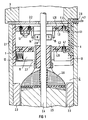
- FIG. 1 shows a partial sectional view of a commutator motor 2 with a motor housing 2.1 with permanent magnets 2.3; 2.3 held on the inside thereof and with a rotor shaft 2.4 with a rotor core package 2.5 fastened thereon, which receives a rotor winding 2.6 connected to a commutator 2.7.
- a gear housing 3 is blocked, into which the rotor shaft 2.4 projects with an extended drive end.
- An insulating body 1 which bears against the inner wall of the motor housing 2.1 and is advantageously fitted as a pre-assembly part, is inserted into the motor housing 2.1 from the end face of the commutator and is fixed in its operating end position.
- a fitted insulating wall part 1.1 which receives contact connections 4-9, is axially inserted into a cutout provided on the face side in the wall of the insulating body 1.
- the insulating body wall part 1.1 receives the contact tracks and with a brush support plate 1.2 and an electronics connection plate 1.3.
- the insulating body wall part 1.1 is first inserted axially into the corresponding wall cutout of the insulating body 1.
- the insulating body wall part 1.1 takes - such as 2 shows - six contact connections 4-9 between inner motor connections or equipped electrical components and outer electrical supply or control lines.
- a contact connection 4 injected into the insulating body wall part 1.1 can be seen completely, which has an angled contact leg 4.1 in a lower contact plane from the insulating body wall part 1.1 protrudes.
- a plug contact 4.3 of the contact connection 4 protrudes out of the motor housing 2.1 from the insulating body wall part 1.1.
- the plug contacts protruding from the motor housing 2.1 are extrusion-coated with a seal 2.9, which in the present case can be squeezed in a sealing manner between the end face of the motor housing 2.1 and a blocked gear housing 3.
- a brush support plate 1.2 and then an electronic connection plate 1.3 are inserted as previously assembled components and then in their axial end position, e.g. fixed by a snap lock and / or an ultrasonic welding.
- the brush support plate 1.2 or the electronics connection plate 1.3 are already equipped before being inserted axially into the insulating body 1.
- brushes 11 with brush pressure springs 12 receiving brush boxes 10 are fixed and electrical brush connections are contacted with contact tracks of a lead frame 1.21 cast into the brush support plate 1.2 as a connecting means in a manner not shown here.
- the contacting of electrical components or electrical connections with one another by means of a lead frame is known per se.
- Such a lead frame has, before being poured into the brush support plate 1.2, connecting webs between contact tracks for their local pre-positioning, which can be punched free after being poured into the brush support plate 1.2. To connect the contact track 4, which is completely visible in FIG.
- the lead frame 1.21 forms - as can be seen in the right part of the brush support plate 1.2 in FIG. 1 - a socket which can be plugged onto the axially bent contact leg 4.1 of the contact track 4 when the brush support plate 1.2 is inserted axially into the insulating body 1.
- soldering is provided, for example by microflame soldering or hot dip soldering.
- the electronics connection plate 1.3 is also inserted into the insulating body 1, e.g. by inserting it into the bushings of a lead frame 1.31 and then soldering it with e.g. a resistor 13 or equipped with Hall converters 14 or 15, which are assigned to a magnet wheel 2.8 attached to the rotor shaft for speed detection.
- a resistor 13 or equipped with Hall converters 14 or 15 which are assigned to a magnet wheel 2.8 attached to the rotor shaft for speed detection.
- the contact track 4 has a connector 4.3 protruding from the motor housing 2.1.
- This connector 4.3 is expediently in a corresponding plane with connectors of other contact connections. All connectors are sealed by an overmolded seal 2.9 between the front of the motor housing 2.1 and the blocked gear housing 2.9.
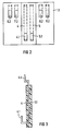
- FIG. 2 shows a radial top view of the inside of an insulating body wall part 1.1 with two contact legs 4.1 or 5.1 assigned to the brush support plate 1.2 in the lower contact plane and a total of six contact legs 6.2-9.2 assigned to the electronics connection plate 1.3 in the upper contact plane.
- FIG. 3 shows, as an alternative to the insulating body wall part 1.1 in FIG. 1, with a connecting plug 4.3 which leads outward from the motor housing 2.1, an insulating body wall part 1.1 with a plug contact 4.4 leading inside the blocked gear housing 3, to which a customer-specific plug then plunging into the gear housing is insertable for an external electrical supply line.
Landscapes
- Engineering & Computer Science (AREA)
- Power Engineering (AREA)
- Motor Or Generator Frames (AREA)
- Motor Or Generator Current Collectors (AREA)
Description
- Die Erfindung bezieht sich auf ein Bürstensystem für einen Kommutatormotor gemäß Oberbegriff des Anspruchs 1; ein derartiges Bürstensystem ist aus der DE-C1 36 32 594 bekannt.
- Im bekannten vorgenannten Fall ist in das kommutatorseitige Ende des Motorgehäuses eine an dessen Innenwandung anliegende Isolierhülse eingeschoben, die in ihrer axialen Länge zumindest den Kommutatorbereich übergreift. In die Isolierhülse ist eine Bürstentragplatte axial eingesetzt, an der den Kommutator beschleifende Bürsten gehaltert sind und in die nach außen aus dem im fertigen Montagezustand durch einen Lagerdeckel geschlossenen Motorgehäuse herausragende Steckerkontakte zum Anschluß äußerer elektrischer Versorgungsleitungen an die Bürstenanschlüsse fest eingespritzt sind.
- Durch die DE-A-31 38 047 ist ein zweiteiliges Motorgehäuse mit einer außen direkt an einem ersten Motorgehäuseteil anliegenden Bürstentragplatte und darauf gehaltener Schaltplatine bekannt; in Nachbarschaft zu dieser Schaltplatine ist ein sich radial zwischen den Wandungen eines zweiten Motorgehäuseteils erstreckendes und an diesem anliegendes Richtteil aus isolierendem Material vorgesehen, um Klemmen eines axial vorliegenden, an radial in den Motorgehäusemantel angeformten Haltearmen befestigten Schalters mit Kontakten der Schaltplatine in Berührung zu bringen.
- Ausgehend von einem Bürstensystem der eingangs genannten Art kann ein mit einfachen Mitteln und mit wenigen unterschiedlichen Bauteilen an verschiedene äußere Versorgungsanschluß-Figurationen und verschiedene innere Bauteile-Bestückungen anpaßbares Universal-Bürstensystem erfindungsgemäß durch die Lehre des Anspruchs 1 erreicht werden; vorteilhafte Ausgestaltungen der Erfindung sind jeweils Gegenstand der Unteransprüche.
- Die erfindungsgemäße Konstruktion erlaubt z.B. bei sonst gleichen Bauteilen des Bürstensystems eine Anpassung an unterschiedliche äußere Versorgungsanschluß-Figurationen und/oder an unterschiedliche Bestückungen der Bürstenplatte, z.B. mit Entstörmitteln, lediglich durch entsprechend spezifische Ausgestaltung der von dem Isolierkörper-Wandteil aufzunehmenden Kontaktverbindungen und/oder Bürstentragplatte.
- Soll z.B. zur Drehzahlregelung des Elektromotors eine entsprechende Elektronik zur Drehzahlerfassung bzw. Drehzahlregelung vorgesehen werden, so ist zweckmäßigerweise nach einer Ausgestaltung der Erfindung zusätzlich eine in axialem Abstand zur Bürstentragplatte ebenfalls axial in den hülsenförmigen Isolierkörper einfügbare und über Kontaktbeine einer weiteren Kontaktebene des Isolierkörper-Wandteils kontaktiertbare Elektronik-Anschlußplatte mit ebenfalls individueller Bestückungsmöglichkeit leicht montier- und anschließbar.
- Zweckmäßigerweise sind derart abgewinkelte Kontaktbeine an den aus dem Isolierkörper-Wandteil herausragenden Enden der Kontaktverbindungen vorgesehen, daß die korrespondierenden Gegenkontakte auf der Bürstentragplatte bzw. der Elektronik-Anschlußplatte in Form von Kontaktbuchsen beim axialen Einfügen der Bürstentragplatte bzw. der Elektronik-Anschlußplatte auf die Kontaktbeine steckbar sind. Die äußeren freien Enden der in dem Isolierkörper-Wandteil gehaltenen Kontaktverbindungen sind nach Ausgestaltungen der Erfindung, insbesondere in Anpassung an verschiedene kundenspezifische Anschlußmöglichkeiten äußerer Versorgungsleitungen, entweder als aus dem Motorgehäuse herausgeführte oder in ein an das Motorgehäuse angeblocktes Getriebegehäuse führende Steckerkontakte ausgebildet.
- Die Erfindung sowie weitere vorteilhafte Ausgestaltungen der Erfindung gemäß Merkmalen der Unteransprüche werden im folgenden anhand schematisch dargestellter Ausführungsbeispiele in der Zeichnung näher erläutert; darin zeigen
- FIG 1
- in einem axialen Teilschnittbild einen Kommutatormotor mit angeblocktem Getriebegehäuse
- FIG 2
- eine radiale Draufsicht auf die Innenseite des Isolierkörper-Wandteils gemäß FIG 1
- FIG 3
- eine tangentiale Draufsicht auf eine Alternative zu dem in FIG 1 vorgesehenen Isolierkörper-Wandteil.
- FIG 1 zeigt in einem Teilschnittbild einen Kommutatormotor 2 mit einem Motorgehäuse 2.1 mit an dessen Innenseite gehaltenen Dauermagneten 2.3;2.3 und mit einer Rotorwelle 2.4 mit darauf befestigtem Rotorbleckpaket 2.5, das eine an einen Kommutator 2.7 angeschlossene Rotorwicklung 2.6 aufnimmt. An die obere Stirnseite des Motorgehäuses 2.1 ist unter Zwischenlage einer Flachdichtung 2.2 ein Getriebegehäuse 3 angeblockt, in das die Rotorwelle 2.4 mit einem verlängerten Antriebsende hineinragt.
- In das Motorgehäuse 2.1 ist von der kommutatorseitigen Stirnseite her ein an der Innenwandung des Motorgehäuses 2.1 anliegender, in vorteilhafter Weise als Vormontageteil bestückter, Isolierkörper 1 eingeschoben und in seiner Betriebsendlage fixiert. In einen in der Wand des Isolierkörpers 1 vorgesehenen stirnseitig offenen Ausschnitt ist ein eingepaßtes Isolier-Wandteil 1.1 axial eingefügt, das Kontaktverbindungen 4-9 aufnimmt.
- Zur Vormontage des Isolierkörpers 1 wird dieser sowohl mit dem die Kontaktbahnen aufnehmenden Isolierkörper-Wandteil 1.1 als auch mit einer Bürstentragplatte 1.2 sowie einer Elektronik-Anschlußplatte 1.3 bestückt. Dazu ist zunächst das Isolierkörper-Wandteil 1.1 in den korrespondierenden Wandausschnitt des Isolierkörpers 1 axial eingefügt. Der Isolierkörper-Wandteil 1.1 nimmt - wie z.B. aus FIG 2 ersichtlich - sechs Kontaktverbindungen 4-9 zwischen inneren Motoranschlüssen bzw. bestückten elektrischen Bauteilen und äußeren elektrischen Versorgungs- bzw. Steuerleitungen auf.
- Im Schnittbild gemäß FIG 1 ist eine in den Isolierkörper-Wandteil 1.1 eingespritzte Kontaktverbindung 4 vollständig ersichtlich, die mit einem abgewinkelten Kontaktbein 4.1 in einer unteren Kontaktebene aus dem Isolierkörper-Wandteil 1.1 herausragt. Zum äußeren Anschluß, z.B. eines kundenspezifischen Steckers für eine äußere Versorgungsleitung, ragt aus dem Isolierkörper-Wandteil 1.1 ein Steckerkontakt 4.3 der Kontaktverbindung 4 aus dem Motorgehäuse 2.1 heraus. Die aus dem Motorgehäuse 2.1 herausragenden Steckerkontakte sind mit einer Dichtung 2.9 umspritzt, die im vorliegenden Fall zwischen der Stirnseite des Motorgehäuses 2.1 und einem angeblockten Getriebegehäuse 3 dichtend einquetschbar ist.
- Zur weiteren Bestückung des vormontierten Isolierkörpers 1 sind nach dem axialen Einfügen des Isolierkörper-Wandteils 1.1 als zuvor bestückte Bauteile eine Bürstentragplatte 1.2 und danach in axialem Abstand eine Elektronik-Anschlußplatte 1.3 eingefügt und in ihrer Betriebsendlage, z.B. durch einen Rastverschluß und/oder eine Ultraschall-Verschweißung, fixiert.
- Auch die Bürstentragplatte 1.2 bzw. die Elektronik-Anschlußplatte 1.3 sind vor dem axialen Einfügen in den Isolierkörper 1 bereits bestückt. So sind z.B. an der Unterseite der Bürstentragplatte 1.2 Bürsten 11 mit Bürstenandruckfedern 12 aufnehmende Bürstenkästen 10 fixiert und elektrische Bürstenanschlüsse mit Kontaktbahnen eines als Verbindungsmittel in die Bürstentragplatte 1.2 eingegossenen Stanzgitters 1.21 in hier nicht näher dargestellter Weise kontaktiert. Die Kontaktgabe elektrischer Bauteile bzw. elektrischer Anschlüsse untereinander durch ein Stanzgitter ist an sich bekannt. Ein derartiges Stanzgitter weist vor dem Eingießen in die Bürstentragplatte 1.2 Verbindungsstege zwischen Kontaktbahnen zu deren örtlicher Vor-Positionierung auf, die nach dem Einguß in die Bürstentragplatte 1.2 freistanzbar sind. Zum Anschluß der in FIG 1 vollständig ersichtlichen Kontaktbahn 4 und den elektrischen Verbindungen der Bürstentragplatte 1.2 bildet das Stanzgitter 1.21 - wie im rechten Teil der Bürstentragplatte 1.2 in FIG 1 ersichtlich - eine Buchse, die beim axialen Einfügen der Bürstentragplatte 1.2 in den Isolierkörper 1 auf das axial hochgebogene Kontaktbein 4.1 der Kontaktbahn 4 aufsteckbar ist. Zur endgültigen elektrischen Kontaktierung zwischen dem Kontaktbein 4.1 einerseits und der vom Stanzgitter 1.21 gebildeten Buchse andererseits ist einer Verlötung, z.B. durch Mikroflamm-Löten bzw. Hubtauch-Löten vorgesehen.
- In ähnlicher Weise wie die Bürstentragplatte 1.2 ist auch die Elektronik-Anschlußplatte 1.3 vor ihrem axialen Einfügen in den Isolierkörper 1, z.B. durch Einstecken in Buchsen eines Stanzgitters 1.31 und anschließendes Verlöten, mit z.B. einem Widerstand 13 bzw. mit Hallwandlern 14 bzw. 15 bestückt, die einem auf der Rotorwelle befestigten Magnetrad 2.8 zur Drehzahlerfassung zugeordnet sind. Zur elektrischen Verbindung zwischen der Elektronik-Anschlußplatte 1.3 und den äußeren Versorgungsanschlüssen dienen in einer oberen Kontaktebene Kontaktbeine 6.2-9.2, von denen in FIG 1 nur das abgebogene Kontaktbein 7.2 sichtbar ist, das in eine Kontaktbuchse des Stanzgitters 1.31 beim axialen Einfügen der Elektronik-Anschlußplatte 1.3 eintaucht.
- Zum äußeren kundenspezifischen Verbinden der Kontaktbahnen mit einem äußeren Anschlußstecker weist gemäß FIG 1 die Kontaktbahn 4 einen aus dem Motorgehäuse 2.1 herausragenden Anschlußstecker 4.3 auf. Dieser Anschlußstecker 4.3 liegt zweckmäßigerweise in einer korrespondierenden Ebene mit Anschlußsteckern weiterer Kontaktverbindungen. Sämtliche Anschlußstecker sind durch eine umspritzte Dichtung 2.9 zwischen der Stirnseite des Motorgehäuses 2.1 und dem angeblockten Getriebegehäuse 2.9 dichtend eingeschlossen.
- FIG 2 zeigt eine radiale Draufsicht auf die Innenseite eines Isolierkörper-Wandteils 1.1 mit zwei der Bürstentragplatte 1.2 zugeordneten Kontaktbeinen 4.1 bzw. 5.1 in der unteren Kontaktebene und insgesamt sechs, der Elektronik-Anschlußplatte 1.3 zugeordneten Kontaktbeinen 6.2-9.2 in der oberen Kontaktebene.
- FIG 3 zeigt alternativ zu dem Isolierkörper-Wandteil 1.1 in FIG 1 mit einem nach außen aus dem Motorgehäuse 2.1 herausgeführten Anschlußstecker 4.3 einen Isolierkörper-Wandteil 1.1 mit einer innerhalb des angeblockten Getriebegehäuses 3 führenden Steckerkontakt 4.4, an den dann ein in das Getriebegehäuse eintauchender kundenspezifischer Stecker für eine äußere elektrische Versorgungsleitung einführbar ist.
Claims (10)
- Bürstensystem für einen Kommutatormotor mit einem in dessen Motorgehäuse (2.1) axial einfügbaren hülsenförmigen Isolierkörper (1) und daran gehaltener, axial einfügbarer Bürstentragplatte (1.2) mit Kontaktverbindungen (4-9) zumindest zwischen den Bürstenanschlüssen und äußeren elektrischen Versorgungsanschlüssen, dadurch gekennzeichnet, daß die Kontaktverbindungen (4-9) in einem axial in einen korrespondierenden Ausschnitt des Isolierkörpers (1) einfügbaren Isolierkörper-Wandteil (1.1) gehalten und in der Betriebsendlage von Isolierkörper-Wandteil (1.1) und Bürstentragplatte (1.2) über aus dem Isolierkörper-Wandteil (1.1) freistehende Kontaktbeine (4.1;5.1) einer ersten Kontaktebene mit Gegenkontakten (Stanzgitter 1.21) der Bürstentragplatte (1.2) kontaktiert sind.
- Bürstensystem nach Anspruch 1, gekennzeichnet durch zumindest eine in axialem Abstand zur Bürstentragplatte (1.2) axial einfügbare und über Kontaktbeine (6.2-9.2) einer weiteren Kontaktebene des Isolierkörper-Wandteils (1.1) kontaktierbare Elektronik-Anschlußplatte (1.3).
- Bürstensystem nach Anspruch 1 oder 2, dadurch gekennzeichnet, daß die Kontaktbeine (4.1;5.1 bzw.6.2-9.2) mit korrespondierenden Gegenkontakten eines in die vorzugsweise aus Kunststoff bestehende Bürstentragplatte (1.2) und/oder Elektronik-Anschlußplatte (1.3) eingespritzten Stanzgitters (1.21 bzw.1.31) kontaktiert sind.
- Bürstensystem nach einem der Ansprüche 1-3, gekennzeichnet durch derart abgewinkelte Kontaktbeine (4.1;5.1 bzw.6.2-9.2), daß die korrespondierenden Gegenkontakte in Form von Kontaktbuchsen beim axialen Einfügen der Bürstentragplatte (1.2) bzw. der Elektronik-Anschlußplatte (1.3) auf die Kontaktbeine aufsteckbar sind.
- Bürstensystem nach Anspruch 4, dadurch gekennzeichnet, daß die Kontaktbuchsen mit den eingesteckten Kontaktbeinen verlötet sind.
- Bürstensystem nach einem der Ansprüche 1-5, gekennzeichnet durch aus dem Isolierkörper-Wandteil (1.1) herausragende Kontaktmittel (Steckerkontakte 4.3 bzw.4.4) zur Kontaktierung mit einem äußeren elektrischen Versorgungsanschluß.
- Bürstensystem nach Anspruch 6, dadurch gekennzeichnet, daß die Steckerkontakte (4.2) aus dem Motorgehäuse (2.1) des Elektromotors (1) herausgeführt sind.
- Bürstensystem für einen Kommutatormotor mit einem axial angeblockten Getriebegehäuse nach Anspruch 6, dadurch gekennzeichnet, daß die Steckerkontakte (4.3) innerhalb des Getriebegehäuses (3) hineinragen.
- Bürstensystem nach Anspruch 7 oder 8, gekennzeichnet durch eine, vorzugsweise gespritzte, die Steckerkontakte (4.2 bzw.4.3) einschließende Dichtung (2.9).
- Bürstensystem nach einem der Ansprüche 1-9, dadurch gekennzeichnet, daß das Isolierkörper-Wandteil (1.1), die Bürstentragplatte (1.2) und gegebenenfalls zumindest eine Elektronik-Platte (1.3) in der gleichen Axialrichtung relativ zu dem Isolierkörper (1) bzw. dem Isolierkörper-Wandteil (1.1) fügbar sind.
Priority Applications (3)
| Application Number | Priority Date | Filing Date | Title |
|---|---|---|---|
| DE59005769T DE59005769D1 (de) | 1990-12-07 | 1990-12-07 | Bürstensystem für einen Kommutatormotor. |
| EP19900123575 EP0489940B1 (de) | 1990-12-07 | 1990-12-07 | Bürstensystem für einen Kommutatormotor |
| ES90123575T ES2053063T3 (es) | 1990-12-07 | 1990-12-07 | Sistema de escobillas para un motor de colector. |
Applications Claiming Priority (1)
| Application Number | Priority Date | Filing Date | Title |
|---|---|---|---|
| EP19900123575 EP0489940B1 (de) | 1990-12-07 | 1990-12-07 | Bürstensystem für einen Kommutatormotor |
Publications (2)
| Publication Number | Publication Date |
|---|---|
| EP0489940A1 EP0489940A1 (de) | 1992-06-17 |
| EP0489940B1 true EP0489940B1 (de) | 1994-05-18 |
Family
ID=8204811
Family Applications (1)
| Application Number | Title | Priority Date | Filing Date |
|---|---|---|---|
| EP19900123575 Expired - Lifetime EP0489940B1 (de) | 1990-12-07 | 1990-12-07 | Bürstensystem für einen Kommutatormotor |
Country Status (3)
| Country | Link |
|---|---|
| EP (1) | EP0489940B1 (de) |
| DE (1) | DE59005769D1 (de) |
| ES (1) | ES2053063T3 (de) |
Cited By (2)
| Publication number | Priority date | Publication date | Assignee | Title |
|---|---|---|---|---|
| CN102005886A (zh) * | 2009-08-28 | 2011-04-06 | 通用汽车环球科技运作公司 | 减小有刷电机电流和扭矩波动的方法和采用该方法的电机 |
| EP0878338B2 (de) † | 1997-05-16 | 2013-07-10 | Robert Bosch Gmbh | Elektromotorischer Antrieb |
Families Citing this family (18)
| Publication number | Priority date | Publication date | Assignee | Title |
|---|---|---|---|---|
| EP0601228B1 (de) * | 1992-12-08 | 1994-10-19 | Siemens Aktiengesellschaft | Elektromotorischer Antrieb |
| DE59305082D1 (de) * | 1993-08-26 | 1997-02-20 | Siemens Ag | Welle mit darauf konzentrisch gehaltenem Magnetkörper |
| FR2713412B1 (fr) * | 1993-11-29 | 1996-01-05 | Valeo Equip Electr Moteur | Dispositif de raccordement électrique, porte-balais de machine électrique tournante comportant un tel dispositif de raccordement et alternateur de véhicule automobile équipé d'un tel porte-balais. |
| DE4444645A1 (de) * | 1994-12-15 | 1996-06-20 | Teves Gmbh Alfred | Bürstentrageplatte |
| DE19536696A1 (de) * | 1995-09-30 | 1997-04-03 | Teves Gmbh Alfred | Elektromotor-Pumpen-Aggregat |
| FR2750811B1 (fr) * | 1996-07-02 | 2004-01-23 | Valeo Systemes Dessuyage | Moto-reducteur pour l'entrainement d'au moins un bras d'essuie-glace, et procede de montage d'une borne d'alimentation dans le socle d'un tel moto-reducteur |
| DE19705833A1 (de) * | 1997-02-15 | 1998-08-20 | Itt Mfg Enterprises Inc | Bürstenhalteanordnung |
| DE19815702A1 (de) | 1998-04-08 | 1999-10-14 | Bosch Gmbh Robert | Elektromotorischer Antrieb |
| DE19852251C1 (de) * | 1998-11-12 | 2000-03-30 | Siemens Ag | Entstörter Kommutatormotor, insbesondere drehzahlstellbarer Kraftfahrzeug-Servomotor |
| DE19945657C1 (de) * | 1999-09-23 | 2001-03-15 | Siemens Ag | Kommutatormotor mit einer Drehzahl- und/oder Drehrichtungs-Sensorvorrichtung |
| DE10061905A1 (de) * | 2000-12-12 | 2002-06-13 | Continental Teves Ag & Co Ohg | Aggregat mit einem Motor |
| DE10133767A1 (de) * | 2001-07-11 | 2003-01-30 | Temic Auto Electr Motors Gmbh | Kommutatormotor mit einem zylinderförmigen Motorgehäuse |
| DE102004045627A1 (de) * | 2004-09-21 | 2006-04-06 | Robert Bosch Gmbh | Elektronikhalter für eine elektrische Maschine |
| FR2876844A1 (fr) * | 2004-10-15 | 2006-04-21 | Arvinmeritor Light Vehicle Sys | Motoreducteur et procede d'assemblage du motoreducteur |
| FR2897484A1 (fr) * | 2006-02-15 | 2007-08-17 | Arvinmeritor Light Vehicle Sys | Dispositif d'entrainement, ouvrant de vehicule automobile et procede de realisation d'une ligne equipotentielle dans un dispositif d'entrainement |
| DE102007063694A1 (de) | 2007-09-25 | 2010-09-09 | Magna Powertrain Ag & Co Kg | Getriebeinheit |
| DE102014104418A1 (de) * | 2014-03-28 | 2015-10-01 | Küster Holding GmbH | Elektrisch schaltbare Kraftfahrzeugverglasung |
| DE102017223061A1 (de) * | 2017-12-18 | 2019-06-19 | Bühler Motor GmbH | Kommutatormotor und baureihe von kommutatormotoren |
Family Cites Families (3)
| Publication number | Priority date | Publication date | Assignee | Title |
|---|---|---|---|---|
| US4110651A (en) * | 1977-03-17 | 1978-08-29 | Litton Systems, Inc. | Brush block assembly |
| JPS5761480A (en) * | 1980-09-26 | 1982-04-13 | Hitachi Koki Kk | Motor tool |
| DE3823404C3 (de) * | 1988-07-09 | 1995-06-29 | Schunk Motorensysteme | Durchführung für elektrische Kabel |
-
1990
- 1990-12-07 DE DE59005769T patent/DE59005769D1/de not_active Expired - Lifetime
- 1990-12-07 EP EP19900123575 patent/EP0489940B1/de not_active Expired - Lifetime
- 1990-12-07 ES ES90123575T patent/ES2053063T3/es not_active Expired - Lifetime
Cited By (3)
| Publication number | Priority date | Publication date | Assignee | Title |
|---|---|---|---|---|
| EP0878338B2 (de) † | 1997-05-16 | 2013-07-10 | Robert Bosch Gmbh | Elektromotorischer Antrieb |
| CN102005886A (zh) * | 2009-08-28 | 2011-04-06 | 通用汽车环球科技运作公司 | 减小有刷电机电流和扭矩波动的方法和采用该方法的电机 |
| CN102005886B (zh) * | 2009-08-28 | 2016-10-05 | 通用汽车环球科技运作公司 | 减小有刷电机电流和扭矩波动的方法和采用该方法的电机 |
Also Published As
| Publication number | Publication date |
|---|---|
| DE59005769D1 (de) | 1994-06-23 |
| EP0489940A1 (de) | 1992-06-17 |
| ES2053063T3 (es) | 1994-07-16 |
Similar Documents
| Publication | Publication Date | Title |
|---|---|---|
| EP0489940B1 (de) | Bürstensystem für einen Kommutatormotor | |
| EP2182616B1 (de) | Bürstenloser Gleichstrommotor | |
| EP0996213B1 (de) | Motoranschlussstecker, insbesondere für einen drehzahlstellbaren Kommutatormotor | |
| EP0618659A1 (de) | Kommutatormotor-Getriebe-Antriebseinheit, insbesondere Kraftfahrzeug-Fensterheberantrieb | |
| DE19710015A1 (de) | Motor mit Drehzahlabgriff über einen Hall-Sensor | |
| DE102012218847A1 (de) | Anschlusselement für eine Antriebsanordnung sowie eine Antriebsanordnung mit einem Anschlussteil | |
| WO2007054395A1 (de) | Getriebe-antriebseinheit mit elektronik-einsteckmodul | |
| EP0220447A1 (de) | Elektromotor, insbesondere dauermagneterregter Aussenläufermotor | |
| EP0645875A1 (de) | Motor-Pumpen-Aggregat, insbesondere Kraftfahrzeug-Antiblockier-Bremsvorrichtung | |
| DE102016204954A1 (de) | Elektrische Maschine sowie Verfahren zum Herstellen einer elektrischen Maschine | |
| DE102008051545A1 (de) | Elektronisches Gerät mit Mehrkontaktstecker und Verfahren zur Herstellung desselben | |
| DE10130117A1 (de) | Gehäusedeckel für einen Elektromotor, insbesondere für einen elektronisch kommutierten Gleichstrommotor | |
| EP1776738B1 (de) | Anschlussvorrichtung für einen elektromotor | |
| DE10005505B4 (de) | Heizungspumpe | |
| DE102012104259B4 (de) | Gleichstrommotor zum Antrieb von Aggregaten eines Kraftfahrzeugs | |
| DE10162247C1 (de) | Motor-Pumpen-Aggregat, insbesondere Kraftfahrzeug-Bremsvorrichtung | |
| EP0105392A2 (de) | Kasten-Bürstenhalter für einen Elektro-Kommutatormotor | |
| DE102015211147A1 (de) | Antriebseinheit | |
| EP1351845B1 (de) | Motor-pumpen-aggregat, insbesondere eine kraftfahrzeug-antiblockierbremsvorrichtung | |
| DE102018218527A1 (de) | Gehäusedeckel für eine elektrische Maschine und Verfahren zum Herstellen eines Gehäusedeckels | |
| EP0849866A1 (de) | Kommutator-Stellmotor mit hochauflösender Dreherkennung | |
| DE3434429C2 (de) | ||
| DE19858231A1 (de) | Elektrische Antriebseinheit für Fahrzeugaggregate | |
| EP1247323A1 (de) | Elektrisch betrieber motor | |
| EP0880218B1 (de) | Funkenstörter Elektromotor, insbesondere zum Antrieb eines Kraftfahrzeug-Gebläses |
Legal Events
| Date | Code | Title | Description |
|---|---|---|---|
| PUAI | Public reference made under article 153(3) epc to a published international application that has entered the european phase |
Free format text: ORIGINAL CODE: 0009012 |
|
| 17P | Request for examination filed |
Effective date: 19901207 |
|
| AK | Designated contracting states |
Kind code of ref document: A1 Designated state(s): DE ES FR IT |
|
| 17Q | First examination report despatched |
Effective date: 19931027 |
|
| GRAA | (expected) grant |
Free format text: ORIGINAL CODE: 0009210 |
|
| AK | Designated contracting states |
Kind code of ref document: B1 Designated state(s): DE ES FR IT |
|
| REF | Corresponds to: |
Ref document number: 59005769 Country of ref document: DE Date of ref document: 19940623 |
|
| REG | Reference to a national code |
Ref country code: ES Ref legal event code: FG2A Ref document number: 2053063 Country of ref document: ES Kind code of ref document: T3 |
|
| ITF | It: translation for a ep patent filed | ||
| ET | Fr: translation filed | ||
| PLBE | No opposition filed within time limit |
Free format text: ORIGINAL CODE: 0009261 |
|
| STAA | Information on the status of an ep patent application or granted ep patent |
Free format text: STATUS: NO OPPOSITION FILED WITHIN TIME LIMIT |
|
| 26N | No opposition filed | ||
| PGFP | Annual fee paid to national office [announced via postgrant information from national office to epo] |
Ref country code: ES Payment date: 20001220 Year of fee payment: 11 |
|
| PGFP | Annual fee paid to national office [announced via postgrant information from national office to epo] |
Ref country code: FR Payment date: 20001222 Year of fee payment: 11 |
|
| PG25 | Lapsed in a contracting state [announced via postgrant information from national office to epo] |
Ref country code: FR Free format text: LAPSE BECAUSE OF NON-PAYMENT OF DUE FEES Effective date: 20020830 |
|
| REG | Reference to a national code |
Ref country code: FR Ref legal event code: ST |
|
| PG25 | Lapsed in a contracting state [announced via postgrant information from national office to epo] |
Ref country code: ES Free format text: LAPSE BECAUSE OF NON-PAYMENT OF DUE FEES Effective date: 20021208 |
|
| REG | Reference to a national code |
Ref country code: ES Ref legal event code: FD2A Effective date: 20030113 |
|
| PG25 | Lapsed in a contracting state [announced via postgrant information from national office to epo] |
Ref country code: IT Free format text: LAPSE BECAUSE OF NON-PAYMENT OF DUE FEES;WARNING: LAPSES OF ITALIAN PATENTS WITH EFFECTIVE DATE BEFORE 2007 MAY HAVE OCCURRED AT ANY TIME BEFORE 2007. THE CORRECT EFFECTIVE DATE MAY BE DIFFERENT FROM THE ONE RECORDED. Effective date: 20051207 |
|
| PGFP | Annual fee paid to national office [announced via postgrant information from national office to epo] |
Ref country code: DE Payment date: 20091231 Year of fee payment: 20 |
|
| PG25 | Lapsed in a contracting state [announced via postgrant information from national office to epo] |
Ref country code: DE Free format text: LAPSE BECAUSE OF EXPIRATION OF PROTECTION Effective date: 20101207 |