EP0430295A2 - Simulationssystem für Fahrzeugantriebe - Google Patents
Simulationssystem für Fahrzeugantriebe Download PDFInfo
- Publication number
- EP0430295A2 EP0430295A2 EP90123002A EP90123002A EP0430295A2 EP 0430295 A2 EP0430295 A2 EP 0430295A2 EP 90123002 A EP90123002 A EP 90123002A EP 90123002 A EP90123002 A EP 90123002A EP 0430295 A2 EP0430295 A2 EP 0430295A2
- Authority
- EP
- European Patent Office
- Prior art keywords
- power generator
- output
- inertia power
- engine
- low inertia
- Prior art date
- Legal status (The legal status is an assumption and is not a legal conclusion. Google has not performed a legal analysis and makes no representation as to the accuracy of the status listed.)
- Granted
Links
Images


Classifications
-
- G—PHYSICS
- G01—MEASURING; TESTING
- G01M—TESTING STATIC OR DYNAMIC BALANCE OF MACHINES OR STRUCTURES; TESTING OF STRUCTURES OR APPARATUS, NOT OTHERWISE PROVIDED FOR
- G01M13/00—Testing of machine parts
- G01M13/02—Gearings; Transmission mechanisms
-
- G—PHYSICS
- G01—MEASURING; TESTING
- G01M—TESTING STATIC OR DYNAMIC BALANCE OF MACHINES OR STRUCTURES; TESTING OF STRUCTURES OR APPARATUS, NOT OTHERWISE PROVIDED FOR
- G01M13/00—Testing of machine parts
- G01M13/02—Gearings; Transmission mechanisms
- G01M13/025—Test-benches with rotational drive means and loading means; Load or drive simulation
Definitions
- the present invention relates generally to a simulation system for an automotive prime mover, such as, an internal combustion engine, for testing automotive components, such as, an automatic or manual power transmission. More specifically, the present invention relates to a simulation system for an automotive internal combustion engine which provides output characteristic equivalent to that of the automotive engine.
- Japanese Patent First Publications (Tokkai) Nos. 58-38833 and 61-53541 disclose a bench testing system for an automatic power transmission.
- an electric motor or a hydrostatic motor with a speed increasing device is used in place of an automotive internal combustion engine.
- the electric motor or the hydrostatic motor has a much larger inertia in comparison with the automotive engine, it is practically difficult to control operation of those motors, even combined with the speed increasing device, to simulate transitional characteristic of the automotive engine at the shift of a transmission speed ratio.
- the electric motor has a inertial magnitude about 10 times greater than that of the automotive engine.
- the automotive engine simulation systems employing such motors are only useful for testing durability, steady-state characteristic and so forth, of the power transmission, but not for testing transitional characteristic of the power transmission at the speed ratio shifting.
- the above-noted Japanese patent First Publication No. 61-53541 performs correction of a command current for the electric motor to compensate a differential in inertia between the electric motor and the automotive engine, so as to provide simulated transitional torque characteristic similar to that of the automotive engine.
- a substantial delay is caused in controlling the command current, which is not suitable for testing particularly the transitional characteristic of the power transmission since the high-speed response is required for testing same. Accordingly, in this background art, it is difficult to obtain the transitional characteristic data of the power transmission equivalent to those derived by using the automotive engine.
- a simulation system for an automotive internal combustion engine comprises a low inertia power generator including power generating means having relatively high inertia and inertia reducing means for reducing the inertia of the power generating means.
- An engine characteristic generator is provided which receives predetermined engine operation parameter simulated data for deriving a first signal indicative of a first output torque to be derived as an output of the low inertia power generator according to preset engine output torque variation characteristic which is set in terms of the engine operation parameter simulated data.
- First means is provided for deriving a first correction value indicative of a first compensation torque to be compensated at the output of the low inertia power generator in view of a set engine inertia.
- Second means is provided for deriving a second correction value indicative of a second compensation torque to be compensated at the output of the low inertia power generator in view of a set inertia of the low inertia power generator.
- Third means is provided for deriving a third correction value based on the first and second correction values.
- the third correction value is indicative of a third compensation torque to be compensated at the output of the low inertia power generator.
- the third compensation torque compensates a differential in inertia between the engine and the low inertia power generator.
- Fourth means is further provided for deriving a control signal based on the first signal and the third correction value.
- the control signal is fed to the low inertia power generator for controlling operation of the relatively high inertia power generating means so as to provide a second output torque as the output of the low inertia power generator.
- the second output torque is equivalent to the first output torque.
- Fig. 1 is a block diagram showing an overall structure of a bench testing apparatus for an automotive automatic power transmission according to a preferred embodiment of the present invention
- Fig. 2 is a block diagram showing a simulation system for an automotive internal combustion engine according to a preferred embodiment of the present invention
- Fig. 3 is a graph showing output characteristic of a function generator incorporated in the preferred embodiment of Fig. 2, along with resultant output characteristic of a command signal for compensating inertia differential during a constant acceleration or deceleration;
- Fig. 4 is a graph showing output characteristic of an engine characteristic generator incorporated in the preferred embodiment of Fig. 2.
- Fig. 1 a preferred embodiment of an overall structure of a bench testing apparatus or a chassis dynamometer for an automotive power transmission according to the present invention will be described hereinbelow for better understanding of a preferred embodiment of an automotive engine simulation system according to the present invention.
- a low inertia power generator 1 in the form of a so-called transient dynamometer includes a direct current motor having a relatively high inertia which is associated with a Thyristor-Leonard type current control minor loop.
- the direct current motor is further associated with a speed increasing device for reducing the inertia of the direct current motor.
- the motor is controlled by a torque command or a speed command applied through the Thyristor-Leonard type current control minor loop.
- the low inertia power generator is disclosed in co-pending U.S. Patent Applications Serial Nos. 427,031 filed on October 25, 1990 and 436,298 filed on November 13, 1990. The contents of the above-noted co-pending U.S. Patent Applications are incorporated herein by reference for the sake of disclosure.
- the low inertia power generator 1 has an output shaft which is connected via a torque meter 2 to an automotive power transmission 3 to be tested. Accordingly, the power transmission 3 is driven by the output of the low inertia power generator 1. In turn, an output shaft of the power transmission 3 is connected to a dummy load 5 via a torque meter 4. As the dummy load 5, a torque absorbing dynamometer with flywheels is employed.
- Control units 6, 7 and 8 are provided for controlling operations of the low inertia power generator 1, the power transmission 3 and the dummy load dynamometer 5, respectively.
- the control unit 6 is fed with a torque command or a speed command to perform torque control or speed control of the low inertia power generator 1.
- the torque command is in the form of a voltage signal converted in level so as to be indicative of a value which can be directly used for the Thyristor-Leonard type current control minor loop to provide a current value for controlling operation of the direct current motor.
- the torque command is input to the control unit 6 from an engine characteristic generator 9.
- the control unit 6 also receives a monitored direct current indicative signal Is representative of a current value actually supplied to the direct current motor.
- the current actually supplied to the direct current motor is monitored by a DC detector 1a which outputs the signal Is to the control unit 6.
- the control unit 6 performs feedback control of the current applied to the direct current motor based on the voltage signal from the engine characteristic generator 9 and the monitored current signal Is. Specifically, the control unit 6 converts the monitored current signal Is to a corresponding voltage value for comparison with the voltage signal from the engine characteristic generator 9 so as to produce a control signal Vc which is fed to the Thyristor-Leonard type current control minor loop to reduce a differential between the commanded voltage signal and the monitored current signal Is.
- the control unit 6 is further fed with a monitored torque indicative signal T 1 which is used, for example, for updating a torque-voltage characteristic map stored in the engine characteristic generator 9, which will be described later.
- the engine characteristic generator 9 having a microprocessor based unit includes preset output torque characteristic data of the automotive engine in relation to engine speeds and engine throttle valve open angles ⁇ i , as shown in Fig. 4.
- the preset characteristic data of Fig. 4 may be derived through various experiments. As appreciated, on the basis of a throttle valve open angle simulated signal ⁇ i and a speed signal N1 indicative of a revolution speed of the output shaft of the low inertia power generator 1 or a revolution speed of an input side of the power transmission 3, which is monitored by a speed sensor 10, the required torque in the form of a corresponding voltage value is derived using the preset characteristic data of Fig. 4.
- the derived torque is then converted in level using the above-noted torque-voltage characteristic map stored in the engine characteristic generator 9 so as to be indicative of a value which can be used for the Thyristor-Leonard type current control minor loop to provide a current value for controlling the operation of the direct current motor.
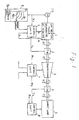
- Fig. 2 shows an automotive engine simulation system according to a preferred embodiment of the present invention.
- the same or similar elements are designated by the same reference numerals as in Fig. 1.
- a block A defined by a dotted line constitutes an inertia compensating circuit and includes a frequency-voltage converter 11.
- the converter 11 receives the speed indicative pulse signal N1 from the speed sensor 10 and converts same into a corresponding voltage signal which is then fed to a differentiating circuit l2.
- the differentiating circuit 12 derives a signal indicative of a speed variation dN/dt. Polarity of the speed variation indicative signal ie positive during acceleration and negative during deceleration.
- An engine inertia setting circuit 14 sets a value indicative of an engine inertia I E which the low inertia power generator 1 simulates to provide.
- the output I E from the engine inertia setting circuit 14 and the speed variation indicative signal from the differentiating circuit 12 are fed to a multiplier circuit 13 which produces a signal indicative of a value of I E (dN/dt).
- the value of I E (dN/dt) indicates a torque for the output of the low inertia power generator 1 to be compensated in view of the set engine inertia at the derived speed variation dN/dt.
- the output of the multiplier 13 is fed to a subtracter circuit 16.
- the output dN/dt of the differentiating circuit l2 is also fed to an inertia setting circuit 15 which sets a value indicative of an inertia of the low inertia power generator 1, to derive a value of I TR-DY (dN/dt) indicative of a torque for the output of the low inertia power generator 1 to be compensated in view of the inertia of the low inertia power generator 1 at the derived speed variation dN/dt.
- the output of the inertia setting circuit 15 is also fed to the subtracter circuit 16.
- the subtracter circuit 16 subtracts the value of I TR-DY (dN/dt) from the value of I E (dN/dt) to derive a value of (I E -I TR-DY )dN/dt indicative of a resultant torque for the output of the low inertia power generator 1 to be compensated in view of the differential between the set engine inertia and the low inertia power generator inertia at the derived speed variation dN/dt.
- the value output from the subtracter circuit 16 is proportional to a torque actually required for compensating the inertia dfferential between the engine and the low inertia power generator 1.
- the output of the subtracter circuit 16, i.e. the output of the block A is then fed to an operational amplifier 17 which converts a level of the output of the subtracter circuit 16 so as to be indicative of a voltage value which can be directly used for the Thyristor-Leonard type current contol minor loop to provide a current value for the direct current motor to provide the actually required torque at the output of the low inertia power generator 1 as a compensation torque.
- the output of the operational amplifier 17 is fed to an adder circuit 18 where a correction value is added to the output from the operational amplifier 17 in case the monitrored speed N 1 of the output shaft of the low inertia power generator 1 is no less than a predetermined basic value N B' wherein the proportional relationship between the applied current and the resultant torque is not attained in the direct current motor, which will be described later with reference to Fig. 3. Accordingly, in case the monitored speed N 1 is less than the basic value N B' no correction value is added at the adder circuit 18.
- An output of the adder circuit 18 is fed to an adder circuit 20 via a switch 19 as an inertia differential compensation voltage signal for compensating the inertia differential between the engine and the low inertia power generator 1 at the output of the latter.
- a switch 19 In case the switch 19 is connected to ground, no inertia compensation is performed.
- the engine characteristic generator 9 derives a command torque T using the throttle valve open angle simulated signal ⁇ i and the monitored speed N1 of the output shaft of the low inertia power generator 1.
- the engine characteristic generator 9 includes torque-voltage conversion means 9a which concerts a level of the derived command torque T so as to be indicative of a voltage value which can be directly used for the Thyristor-Leonard type current control minor loop to provide a current value for the direct current motor to provide the commanded torque T at the output of the low inertia power generator 1.
- the torque-voltage conversion means 9a derives the converted voltage signal using the foregoing torque-voltage characteristic map. The converted voltage signal is fed to the adder 20 as the torque command.
- the adder circuit 20 derives the sum of the inertia differential compensation signal from the adder circuit 18 and the torque command signal from the engine characteristic generator 9 so as to provide a resultant torque command signal to be fed to the control unit 6.
- the resultant torque command signal is indicative of a voltage value which can be directly used for the Thyristor-Leonard type current control minor loop as described above, so as to provide the output characteristic of the low inertia power generator 1 equivalent to that of the automotive engine the inertia of which is set at the engine inertia setting circuit 14.
- an absolute compensation torque for the low inertia power generator 1 is greater than that for the automotive engine, and the absolute compensation torque for the low inertia power generator 1 in the form of a voltage value should be subtracted from the converted voltage value from the engine characteristic generator 9, while, the absolute compensation torque for the automotive engine in the form of a voltage value should be added to the converted voltage value from the engine characteristic generator 9.
- negative command signal from the adder circuit 18 is added at the adder circuit 20 to make less the converted voltage value from the engine characteristic generator 9 so that the inertia differential between the engine and the low inertia power generator 1 is compensated to provide the output characteristic of the low inertia power generator 1 equivalent to the automotive engine.
- the absolute compensation torque for the low inertia power generator 1 in the form of a voltage value should be added to the converted voltage value from the engine characteristic generator 9, while, the absolute compensation torque for the automotive engine in the form of a voltage value should be subtracted from the converted voltage value from the engine characteristic generator 9.
- positive command signal from the adder circuit 18 is added at the adder circuit 20 to make greater the converted voltage value from the engine characteristic generator 9 so as to provide the output characteristic of the low inertia power generator 1 equivalent to the automotive engine.
- positive command signal from the adder circuit 18 is added at the adder circuit 20 to make greater the converted voltage value from the engine characteristic generator 9 during acceleration of the direct current motor, while, negative command signal from the adder circuit 18 is added at the adder circuit 20 to make less the converted voltage value from the engine characteristic generator 9 during deceleration of the direct current motor.
- control unit 6 performs the feedback control of the control signal Vc so as to reduce a differential between the resultant command signal from the adder circuit 20 and the monitored current signal Is.
- a control time delay is caused only in the electric circuit so that a significantly higher control response with a delay of about 0.02 to 0.03 second is attained, which is ten times faster than that in the background art.
- Fig. 3 shows output characteristic of a function generator 21 identified by a line A as well as output characteristic of the adder circuit 18 identified by a line B which is obtained during a costant acceleration or deceleration of the direct current motor.
- the direct current motor outputs a torque proportional to an applied current during the monitored speed N1 of the output shaft of the low inertia power generator 1 being less that, the basic value N B , while, the proportional relationship between the applied current and the resultant torque is not attained at a range of the monitored speed N1 between the basic value N B and a maximum speed value Nm.
- an output voltage Y of the function generator 21 is set to zero during the monitored speed N1 being less than the basic value N B' while, the output voltage Y of the function generator 21 increases linearly with increment of the monitored speed N1 in the range of the monitored speed N1 between N B and Nm.
- the function generator Z1 receives the output of the frequency-voltage converter 11 so as to feed the output Y according to a magnitude of the converted voltage indicative of the monitored speed N1 of the output shaft of the low inertia power generator 1, using the foregoing line A in Fig. 3.
- the output Y of the function generator 21 is then fed to a multiplier circuit 22 which also receives the output X of the foregoing subtracter circuit 16.
- the multiplier circuit 22 processes the outputs x and Y to produce a signal indicative of a value identified by XY/10 which is then fed to the adder circuit 18.
- the output value of the multiplier circuit 22 becomes zero during the monitored speed N1 being less than the basic value N B so that no correction value is added at the adder circuit 18.
- the output value of the multiplier circuit 22 increases with the increment of the monitored speed N1 so that a correction value is added to the output of the operational amplifier 17 at the adder circuit 18 so as to provide the proportional relationship between the applied current and the resultant torque even when the monitored speed N1 is in the speed range between N B and Nm.
- the output from the adder circuit 18 becomes as indicated by the line B in Fig. 3 during a constant acceleration or deceleration of the direct current motor or the low inertia power generator 1.
Landscapes
- Physics & Mathematics (AREA)
- General Physics & Mathematics (AREA)
- Testing Of Devices, Machine Parts, Or Other Structures Thereof (AREA)
- Testing Of Engines (AREA)
Applications Claiming Priority (2)
| Application Number | Priority Date | Filing Date | Title |
|---|---|---|---|
| JP1310883A JPH03170831A (ja) | 1989-11-30 | 1989-11-30 | 駆動試験装置の慣性補償装置 |
| JP310883/89 | 1989-11-30 |
Publications (3)
| Publication Number | Publication Date |
|---|---|
| EP0430295A2 true EP0430295A2 (de) | 1991-06-05 |
| EP0430295A3 EP0430295A3 (en) | 1992-07-15 |
| EP0430295B1 EP0430295B1 (de) | 1995-09-13 |
Family
ID=18010532
Family Applications (1)
| Application Number | Title | Priority Date | Filing Date |
|---|---|---|---|
| EP90123002A Expired - Lifetime EP0430295B1 (de) | 1989-11-30 | 1990-11-30 | Simulationssystem für Fahrzeugantriebe |
Country Status (5)
| Country | Link |
|---|---|
| US (1) | US5086648A (de) |
| EP (1) | EP0430295B1 (de) |
| JP (1) | JPH03170831A (de) |
| KR (1) | KR960014005B1 (de) |
| DE (1) | DE69022369T2 (de) |
Families Citing this family (5)
| Publication number | Priority date | Publication date | Assignee | Title |
|---|---|---|---|---|
| US5537865A (en) * | 1995-01-03 | 1996-07-23 | Shultz; Duane E. | Apparatus and methods for testing transmissions |
| CA2184342A1 (en) * | 1995-09-28 | 1997-03-29 | Robert C. Lam | Fibrous lining material comprising a less fibrillated aramid and synthetic graphite |
| JP3213227B2 (ja) * | 1995-11-21 | 2001-10-02 | 本田技研工業株式会社 | 自動変速機のトルク検出及び制御装置 |
| JP2002176791A (ja) * | 2000-09-26 | 2002-06-21 | Yaskawa Electric Corp | 電動機制御装置 |
| US7921712B1 (en) | 2008-07-24 | 2011-04-12 | Honda Motor Co., Ltd. | Dynamometer test apparatus and method for testing both transmissions and rear differentials |
Citations (2)
| Publication number | Priority date | Publication date | Assignee | Title |
|---|---|---|---|---|
| DE3416496A1 (de) * | 1984-05-04 | 1985-11-07 | Brown, Boveri & Cie Ag, 6800 Mannheim | Verfahren und schaltungsanordnung zum simulieren von pruefstandstraegheitsmomenten |
| EP0369747A2 (de) * | 1988-11-14 | 1990-05-23 | Kabushiki Kaisha Meidensha | System zum Simulieren der Steuerung eines Motor-Kennlinienverlaufs |
Family Cites Families (6)
| Publication number | Priority date | Publication date | Assignee | Title |
|---|---|---|---|---|
| JPS5810625A (ja) * | 1981-07-13 | 1983-01-21 | Toyo Electric Mfg Co Ltd | トランスミッション試験装置 |
| JPS5838833A (ja) * | 1981-08-31 | 1983-03-07 | Mitsubishi Electric Corp | 自動変速機用試験装置における制御方法 |
| JPS6153541A (ja) * | 1984-08-23 | 1986-03-17 | Hitachi Ltd | 駆動試験機の制御装置 |
| US4758967A (en) * | 1986-05-12 | 1988-07-19 | Ford Motor Company | Computer simulated inertia for motor vehicle powertrain testing |
| JPS63148309A (ja) * | 1986-12-12 | 1988-06-21 | Yokogawa Electric Corp | サンプル値調節計 |
| JP2671447B2 (ja) * | 1988-10-25 | 1997-10-29 | 株式会社明電舎 | 変速機の試験装置 |
-
1989
- 1989-11-30 JP JP1310883A patent/JPH03170831A/ja active Granted
-
1990
- 1990-11-29 US US07/619,407 patent/US5086648A/en not_active Expired - Lifetime
- 1990-11-30 EP EP90123002A patent/EP0430295B1/de not_active Expired - Lifetime
- 1990-11-30 KR KR1019900019578A patent/KR960014005B1/ko not_active IP Right Cessation
- 1990-11-30 DE DE69022369T patent/DE69022369T2/de not_active Expired - Fee Related
Patent Citations (2)
| Publication number | Priority date | Publication date | Assignee | Title |
|---|---|---|---|---|
| DE3416496A1 (de) * | 1984-05-04 | 1985-11-07 | Brown, Boveri & Cie Ag, 6800 Mannheim | Verfahren und schaltungsanordnung zum simulieren von pruefstandstraegheitsmomenten |
| EP0369747A2 (de) * | 1988-11-14 | 1990-05-23 | Kabushiki Kaisha Meidensha | System zum Simulieren der Steuerung eines Motor-Kennlinienverlaufs |
Non-Patent Citations (1)
| Title |
|---|
| BBC NACHRICHTEN. vol. 65, no. 11, 1983, MANNHEIM DE pages 385 - 392; HANS-J]RGEN VON THUN: 'DYNAMISCHE NACHBILDUNG VON VERBRENNUNGSMOTOREN AM VOLLELEKTRISCHEN GETRIEBEPR]FSTAND' * |
Also Published As
| Publication number | Publication date |
|---|---|
| JPH03170831A (ja) | 1991-07-24 |
| DE69022369T2 (de) | 1996-02-29 |
| EP0430295B1 (de) | 1995-09-13 |
| KR960014005B1 (ko) | 1996-10-11 |
| JPH0567898B2 (de) | 1993-09-27 |
| DE69022369D1 (de) | 1995-10-19 |
| KR910010174A (ko) | 1991-06-29 |
| US5086648A (en) | 1992-02-11 |
| EP0430295A3 (en) | 1992-07-15 |
Similar Documents
| Publication | Publication Date | Title |
|---|---|---|
| US5534764A (en) | Vehicle driving control system having function for suppressing vibration | |
| US4922869A (en) | Torque controlling apparatus for internal combustion engine | |
| US5355749A (en) | Control apparatus and control method for motor drive vehicle | |
| US4766967A (en) | Oscillation control system for electric motor drive | |
| US6634218B1 (en) | Engine testing apparatus | |
| EP0369747B1 (de) | System zum Simulieren der Steuerung eines Motor-Kennlinienverlaufs | |
| GB2141269A (en) | Vehicle speed control | |
| US5628706A (en) | Method and arrangement for controlling the output power of a drive unit of a motor vehicle | |
| EP0430297B1 (de) | Verfahren und System zur Prüfung von einer Fahrzeugkraftübertragungseinheit an Motoren und Analyse der Motorausgangscharakteristik über die Übertragungseinheit mittels eines Dynamometers | |
| US4621524A (en) | Circuit layout for the simulation of moments of inertia on test stands | |
| US4624349A (en) | Method and apparatus for controlling an electromagnetic clutch for use on a vehicle | |
| US5086648A (en) | Simulation system for automotive prime mover | |
| JPH039238A (ja) | エンジン試験装置における自動運転時のスロットル予測制御装置 | |
| US5189908A (en) | Testing apparatus for engine driven automotive component with feature of precise simulation of engine transition state | |
| EP0430294B1 (de) | System zur Simulation von Fahrzeugantrieben unter Verwendung von elektrisch betriebenen Antrieben hoher Trägheit | |
| EP0393642B1 (de) | Gerät zur Steuerung der Drehzahl für Brennkraftmaschine | |
| US5249458A (en) | System for simulating power plant of automotive vehicle utilizing electrically powered high inertia power plant | |
| JP3503187B2 (ja) | 車両速度制御装置 | |
| Voigt | A control scheme for a dynamical combustion engine test stand | |
| RU2063867C1 (ru) | Самонастраивающийся электропривод робота | |
| von Thun | A new dynamic combustion engine test stand with real-time simulation of the vehicle drive line | |
| US5400756A (en) | Control method and control arrangement for an adjusting device in a motor vehicle | |
| RU2060530C1 (ru) | Самонастраивающийся электропривод | |
| JP4521246B2 (ja) | スロットル制御装置 | |
| JPS6114450B2 (de) |
Legal Events
| Date | Code | Title | Description |
|---|---|---|---|
| PUAI | Public reference made under article 153(3) epc to a published international application that has entered the european phase |
Free format text: ORIGINAL CODE: 0009012 |
|
| AK | Designated contracting states |
Kind code of ref document: A2 Designated state(s): DE FR GB IT |
|
| PUAL | Search report despatched |
Free format text: ORIGINAL CODE: 0009013 |
|
| AK | Designated contracting states |
Kind code of ref document: A3 Designated state(s): DE FR GB IT |
|
| 17P | Request for examination filed |
Effective date: 19920901 |
|
| 17Q | First examination report despatched |
Effective date: 19930720 |
|
| GRAA | (expected) grant |
Free format text: ORIGINAL CODE: 0009210 |
|
| AK | Designated contracting states |
Kind code of ref document: B1 Designated state(s): DE FR GB IT |
|
| ITF | It: translation for a ep patent filed |
Owner name: BUGNION S.P.A. |
|
| REF | Corresponds to: |
Ref document number: 69022369 Country of ref document: DE Date of ref document: 19951019 |
|
| ET | Fr: translation filed | ||
| PLBE | No opposition filed within time limit |
Free format text: ORIGINAL CODE: 0009261 |
|
| STAA | Information on the status of an ep patent application or granted ep patent |
Free format text: STATUS: NO OPPOSITION FILED WITHIN TIME LIMIT |
|
| 26N | No opposition filed | ||
| PGFP | Annual fee paid to national office [announced via postgrant information from national office to epo] |
Ref country code: GB Payment date: 19991028 Year of fee payment: 10 |
|
| PGFP | Annual fee paid to national office [announced via postgrant information from national office to epo] |
Ref country code: FR Payment date: 19991116 Year of fee payment: 10 |
|
| PGFP | Annual fee paid to national office [announced via postgrant information from national office to epo] |
Ref country code: DE Payment date: 19991221 Year of fee payment: 10 |
|
| PG25 | Lapsed in a contracting state [announced via postgrant information from national office to epo] |
Ref country code: GB Free format text: LAPSE BECAUSE OF NON-PAYMENT OF DUE FEES Effective date: 20001130 |
|
| GBPC | Gb: european patent ceased through non-payment of renewal fee |
Effective date: 20001130 |
|
| PG25 | Lapsed in a contracting state [announced via postgrant information from national office to epo] |
Ref country code: FR Free format text: LAPSE BECAUSE OF NON-PAYMENT OF DUE FEES Effective date: 20010731 |
|
| PG25 | Lapsed in a contracting state [announced via postgrant information from national office to epo] |
Ref country code: DE Free format text: LAPSE BECAUSE OF NON-PAYMENT OF DUE FEES Effective date: 20010801 |
|
| REG | Reference to a national code |
Ref country code: FR Ref legal event code: ST |
|
| PG25 | Lapsed in a contracting state [announced via postgrant information from national office to epo] |
Ref country code: IT Free format text: LAPSE BECAUSE OF NON-PAYMENT OF DUE FEES;WARNING: LAPSES OF ITALIAN PATENTS WITH EFFECTIVE DATE BEFORE 2007 MAY HAVE OCCURRED AT ANY TIME BEFORE 2007. THE CORRECT EFFECTIVE DATE MAY BE DIFFERENT FROM THE ONE RECORDED. Effective date: 20051130 |