EP0430061B1 - Heizkessel - Google Patents
Heizkessel Download PDFInfo
- Publication number
- EP0430061B1 EP0430061B1 EP90122283A EP90122283A EP0430061B1 EP 0430061 B1 EP0430061 B1 EP 0430061B1 EP 90122283 A EP90122283 A EP 90122283A EP 90122283 A EP90122283 A EP 90122283A EP 0430061 B1 EP0430061 B1 EP 0430061B1
- Authority
- EP
- European Patent Office
- Prior art keywords
- combustion chamber
- heating
- plate
- water
- heating gas
- Prior art date
- Legal status (The legal status is an assumption and is not a legal conclusion. Google has not performed a legal analysis and makes no representation as to the accuracy of the status listed.)
- Expired - Lifetime
Links
- 238000010438 heat treatment Methods 0.000 claims abstract description 56
- 238000002485 combustion reaction Methods 0.000 claims abstract description 36
- 206010022000 influenza Diseases 0.000 claims abstract description 29
- 238000005192 partition Methods 0.000 claims description 2
- 239000000565 sealant Substances 0.000 claims 1
- 239000007789 gas Substances 0.000 abstract description 46
- XLYOFNOQVPJJNP-UHFFFAOYSA-N water Substances O XLYOFNOQVPJJNP-UHFFFAOYSA-N 0.000 abstract description 17
- 238000005516 engineering process Methods 0.000 abstract description 2
- 238000004519 manufacturing process Methods 0.000 abstract description 2
- 239000002912 waste gas Substances 0.000 abstract 2
- 238000010304 firing Methods 0.000 abstract 1
- 230000007704 transition Effects 0.000 abstract 1
- UGFAIRIUMAVXCW-UHFFFAOYSA-N Carbon monoxide Chemical compound [O+]#[C-] UGFAIRIUMAVXCW-UHFFFAOYSA-N 0.000 description 3
- 239000003546 flue gas Substances 0.000 description 3
- 238000003466 welding Methods 0.000 description 3
- 238000010276 construction Methods 0.000 description 2
- 238000011161 development Methods 0.000 description 2
- 230000018109 developmental process Effects 0.000 description 2
- 230000002349 favourable effect Effects 0.000 description 2
- 239000000446 fuel Substances 0.000 description 1
- 238000003780 insertion Methods 0.000 description 1
- 230000037431 insertion Effects 0.000 description 1
- 239000007788 liquid Substances 0.000 description 1
- 230000035515 penetration Effects 0.000 description 1
Images

Classifications
-
- F—MECHANICAL ENGINEERING; LIGHTING; HEATING; WEAPONS; BLASTING
- F24—HEATING; RANGES; VENTILATING
- F24H—FLUID HEATERS, e.g. WATER OR AIR HEATERS, HAVING HEAT-GENERATING MEANS, e.g. HEAT PUMPS, IN GENERAL
- F24H8/00—Fluid heaters characterised by means for extracting latent heat from flue gases by means of condensation
-
- F—MECHANICAL ENGINEERING; LIGHTING; HEATING; WEAPONS; BLASTING
- F24—HEATING; RANGES; VENTILATING
- F24H—FLUID HEATERS, e.g. WATER OR AIR HEATERS, HAVING HEAT-GENERATING MEANS, e.g. HEAT PUMPS, IN GENERAL
- F24H1/00—Water heaters, e.g. boilers, continuous-flow heaters or water-storage heaters
- F24H1/22—Water heaters other than continuous-flow or water-storage heaters, e.g. water heaters for central heating
- F24H1/24—Water heaters other than continuous-flow or water-storage heaters, e.g. water heaters for central heating with water mantle surrounding the combustion chamber or chambers
- F24H1/26—Water heaters other than continuous-flow or water-storage heaters, e.g. water heaters for central heating with water mantle surrounding the combustion chamber or chambers the water mantle forming an integral body
- F24H1/28—Water heaters other than continuous-flow or water-storage heaters, e.g. water heaters for central heating with water mantle surrounding the combustion chamber or chambers the water mantle forming an integral body including one or more furnace or fire tubes
- F24H1/287—Water heaters other than continuous-flow or water-storage heaters, e.g. water heaters for central heating with water mantle surrounding the combustion chamber or chambers the water mantle forming an integral body including one or more furnace or fire tubes with the fire tubes arranged in line with the combustion chamber
-
- Y—GENERAL TAGGING OF NEW TECHNOLOGICAL DEVELOPMENTS; GENERAL TAGGING OF CROSS-SECTIONAL TECHNOLOGIES SPANNING OVER SEVERAL SECTIONS OF THE IPC; TECHNICAL SUBJECTS COVERED BY FORMER USPC CROSS-REFERENCE ART COLLECTIONS [XRACs] AND DIGESTS
- Y02—TECHNOLOGIES OR APPLICATIONS FOR MITIGATION OR ADAPTATION AGAINST CLIMATE CHANGE
- Y02B—CLIMATE CHANGE MITIGATION TECHNOLOGIES RELATED TO BUILDINGS, e.g. HOUSING, HOUSE APPLIANCES OR RELATED END-USER APPLICATIONS
- Y02B30/00—Energy efficient heating, ventilation or air conditioning [HVAC]
Definitions
- the invention relates to a boiler for burning liquid or gaseous fuels according to the preamble of the main claim.
- Such boilers which in particular as a so-called condensing or. Condensate boilers are operated, for example, according to DE-U-86 17 230.
- the hot gas flues in the area remote from the burner or at the rear end laterally from the burner are designed as a tube or pocket package, at the lower end of which an exhaust gas and condensate collection chamber is arranged.
- the water-carrying housing surrounding the combustion chamber and the heating gas flues is adapted accordingly, that is, there are two correspondingly large pipes which are more or less perpendicularly butted against each other in the area of the heating gas flues and are connected to each other in a liquid-tight manner along a corresponding penetration curve.
- connection ends of the heating gas flues insofar as they are pockets, must be adapted to the cylindrical shape of the combustion chamber and, as far as individual tubes are concerned, there are different tube lengths, the ends of the tubes also being adapted to the cylindrical shape of the combustion chamber have to be.
- there are no ideal flow conditions namely as far as the combustion-side inflow conditions of the heating gases into the heating gas flues are concerned, as well as the outflow conditions on the water side in the connection area of the heating gas flues to the combustion chamber.
- a condensate boiler construction in which the combustion chamber is arranged in an upper, horizontally and the heating gas flues with their lower part in a lower, vertically oriented housing part, which housing parts only by a horizontally inserted partition an upper and lower interior can be divided.
- these tubular heating gas flues with different lengths are adapted in an arc shape to the angular assignment of the two housing parts.
- the invention is therefore based on the object to improve a boiler of the type mentioned in such a way that there are simple cutting conditions for all the sheets or pipes involved, combined with the proviso to improve the flow conditions both on the combustion side and on the water side.
- the upper part containing the combustion chamber and the lower part of the boiler containing the heating gas flues are joined together along a miter cut plane running at approximately 45 °, which applies not only to the tubular casing for the water-bearing housing, but also also consistent for connecting the heating gas flues to the combustion chamber.
- the bottom of the combustion chamber facing the burner is thus formed by a flat plate which faces the burner to a certain extent like a desk and extends in the miter cut plane.
- the heating gas flues are designed as pipes, they only require a corresponding inclined section, where different lengths of cut result for the individual pipes, unless other measures are taken to facilitate them.
- the arrangement of pockets advantageously results in simple rectilinear section lines which considerably simplify the welding or welding of the pockets to the plate.
- the heating gas flues are therefore preferably designed as pockets in a manner known per se.
- the flow conditions both on the combustion and water sides are thus significantly improved. Since the outlets of the hot gas flues are directly opposite the burner, the hot gases can flow directly into the openings of the hot gas flues, which are also at an angle, which also enables the heating gas flues to be filled more evenly. On the water side, the transfer of the transferred heat or water is even more favorable, since the heated water can flow freely upwards on the sloping plate.
- the heating gas flues which are preferably designed as pockets, are arranged with their cross-sectional longitudinal axis oriented in the direction of the inflow.
- the plate can be integrated into the boiler housing in different ways.
- a relevant embodiment consists in that the plate is designed as a separating surface welded to both housing parts and is provided with overflow openings in the area of the water-bearing interior spaces, which overflow openings establish the connection between the two interior spaces of the water-bearing housing parts.
- the second embodiment in this regard is that the gap is connected to the lower housing part, the water-carrying interior of the upper housing part is closed with an annular surface, and both housing parts are connected to one another in the miter cutting plane, the interior of the lower housing part having at least one at the highest Job of the interior, overflow line leading to the boiler flow is provided.
- connection of the two housing parts is not to be understood as a welded connection, but merely a gas-tight connection of the two housing parts to one another, which is possible since each housing part represents a self-contained structure with regard to the water flow, which will be explained in more detail below.
- a condensate drain line which penetrates the lower housing part and opens into the condensate collecting space, is connected to the plate in the region of the lowest combustion chamber surface line.
- an advantageous further development consists in the fact that the lower housing part is closed with a heating gas pull connecting plate extending parallel to the plate forming the bottom of the combustion chamber, which together with a condensate-resistant base plate and a side wall having the flue gas connecting piece limits the flue gas and condensate collecting space provided with condensate drain.
- This heating gas connection plate extends in the lower boiler housing parallel to the miter cut plane, which means that the heating gas cables, regardless of whether they are pockets or pipes, can all be cut to the same length.
- the longitudinal axis of the upper housing part - and thus that of the combustion chamber - is arranged perpendicular to the longitudinal axis of the lower housing part, the miter cutting plane halving or approximately halving the angle of the two longitudinal axes.
- the longitudinal axis of the lower housing part is arranged at an angle of 1 to 10 °, preferably 5 °, with respect to the vertical to the side remote from the burner.
- the plate extending in the miter cut plane is provided with a recess and the ring surface belonging to the upper housing part is provided with an annular collar which is inserted into the recess with the insertion of a suitable ring seal.
- the cohesion of the two housing parts can also be easily achieved by the supply line connections then required from the lower part to the upper part.
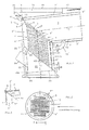
- the boiler consists of a water-bearing housing 3 with a substantially horizontally oriented combustion chamber 1 arranged in the upper part, from which heating gas flues 4 lead to an exhaust gas and condensate collection chamber 20 with exhaust gas connection piece 24 arranged at the bottom of the housing, the heating gas flues 4 and their outlets the combustion chamber 1 in the area remote from the burner are connected. It is essential for this boiler, as can be seen in particular from FIG.
- the housing part 2 containing the combustion chamber 1 and thus the combustion chamber 1 itself and the housing part 6 containing the heating gas flues 4 of the water-carrying housing 3 are joined in a common miter cut plane 7 in a correspondingly inclined, the burner distant bottom 8 of the combustion chamber 1 plate 9 is arranged with heating gas openings 10, to which the heating gas ends 4 'are connected in a liquid-tight manner, and that the water-carrying interiors 2', 6 'of the two housing parts 2, 6 are connected to one another .
- the heating gas flues 4 are designed in the form of pockets 4 ⁇ , the pockets 4 ⁇ being arranged with their cross-sectional longitudinal axes 11 (see FIG. 2) oriented in the inflow direction.
- the plate 9 with the Schuuchö Maschinenen 10 is seen when looking into the combustion chamber 1 from the burner also in the sense of FIG. 2 and only with the difference that the visible edge 9 'of the plate 9 forms an ellipse.
- the outer pockets in width B are correspondingly shorter than the pockets arranged in the inner region. Regardless of this different width dimensioning, the section lines of the pockets are designed to run in a straight line, which considerably simplifies the welding of the pockets to the plate 9 or to the heating gas draw openings 10 punched out therein.
- the heating gas draft openings 10 are, as indicated by arrows C, flowed directly and without prior deflection in the combustion chamber 1, while on the water side in this area the heated water can flow freely in the direction of arrow D upward.
- the plate 9 is designed as a separating surface welded to both housing parts 2, 6 and is provided with overflow openings 12 in the area of the water-carrying interior spaces 2 ', 6'.
- the plate 9 is connected to the lower housing part 6, the water-carrying interior 2 'of the upper housing part 2 is closed with an annular surface 13, and both housing parts 2, 6 are connected to each other in the miter cut plane 7, the interior 6' of the lower housing part with at least one, at the highest point 14 of the interior 6 'attached overflow line 16 is provided.
- the two housing parts are joined together in a gas-tight manner in the miter cut plane 7, sealed with a suitable ring seal 32.
- the plate 9 (see enlarged in FIG. 4) is expediently provided with a recess 30 and the annular surface 13 with an annular collar 31 which, as shown, is inserted into the recess 30.
- the two housing parts 2, 6 can be flanged to a certain extent with just a few screws.
- the lower housing part 6 is completed with a heating gas cable connection plate 22 which extends parallel to the plate 9 at a corresponding distance, the together with a condensate-resistant base plate 23 and a side wall 25 having the exhaust connection piece 24, the exhaust gas and condensate collecting space 20 provided with condensate drain 26 is limited.
- the longitudinal axis 5 of the upper housing part 2 - and thus also that of the combustion chamber 1 - is arranged perpendicular to the longitudinal axis 29 of the lower housing part 6, the miter cut plane 7 den Angle ⁇ of the two longitudinal axes 5, 29 halved or approximately halved.
- the longitudinal axis 29 of the lower housing part 6 is inclined with respect to the vertical V to the side remote from the burner by an angle ⁇ of 1 to 10 °, preferably by 5 °, as shown.
- a boiler flow connection box 17 with flow line 18 is arranged at the highest point 14 'of the interior 2' of the upper housing part 2 which the overflow line 16 of the lower housing part 6 is connected.
- such an overflow line 16 is not absolutely necessary, but is also possible since the heat transfer medium flowing along the plate 9 can pass through the overflow openings 12 into the water-carrying interior 2 'of the upper part 2.
- Such openings are of course arranged evenly distributed over the entire circumference of the plate 9 in the embodiment of FIG. 3.
- a condensate drain line 21 which extends through the lower housing part 6 and opens into the exhaust gas and condensate collection chamber 20.
- the lower and upper housing part 6, 2 are connected to an overflow line 16 ', as shown.
Landscapes
- Engineering & Computer Science (AREA)
- Physics & Mathematics (AREA)
- Thermal Sciences (AREA)
- Chemical & Material Sciences (AREA)
- Combustion & Propulsion (AREA)
- Mechanical Engineering (AREA)
- General Engineering & Computer Science (AREA)
- Instantaneous Water Boilers, Portable Hot-Water Supply Apparatuses, And Control Of Portable Hot-Water Supply Apparatuses (AREA)
- Heat-Pump Type And Storage Water Heaters (AREA)
- Steam Or Hot-Water Central Heating Systems (AREA)
- Chimneys And Flues (AREA)
- Combustion Of Fluid Fuel (AREA)
Priority Applications (1)
| Application Number | Priority Date | Filing Date | Title |
|---|---|---|---|
| AT90122283T ATE85691T1 (de) | 1989-11-27 | 1990-11-22 | Heizkessel. |
Applications Claiming Priority (2)
| Application Number | Priority Date | Filing Date | Title |
|---|---|---|---|
| DE3939133 | 1989-11-27 | ||
| DE3939133A DE3939133C1 (enExample) | 1989-11-27 | 1989-11-27 |
Publications (3)
| Publication Number | Publication Date |
|---|---|
| EP0430061A2 EP0430061A2 (de) | 1991-06-05 |
| EP0430061A3 EP0430061A3 (en) | 1991-09-11 |
| EP0430061B1 true EP0430061B1 (de) | 1993-02-10 |
Family
ID=6394249
Family Applications (1)
| Application Number | Title | Priority Date | Filing Date |
|---|---|---|---|
| EP90122283A Expired - Lifetime EP0430061B1 (de) | 1989-11-27 | 1990-11-22 | Heizkessel |
Country Status (4)
| Country | Link |
|---|---|
| EP (1) | EP0430061B1 (enExample) |
| AT (1) | ATE85691T1 (enExample) |
| DE (1) | DE3939133C1 (enExample) |
| ES (1) | ES2039111T3 (enExample) |
Families Citing this family (1)
| Publication number | Priority date | Publication date | Assignee | Title |
|---|---|---|---|---|
| NL9400980A (nl) * | 1994-06-15 | 1996-01-02 | Atag Verwarming Bv | Warmtewisselaar. |
Family Cites Families (3)
| Publication number | Priority date | Publication date | Assignee | Title |
|---|---|---|---|---|
| DE1696521U (de) * | 1955-01-07 | 1955-04-14 | Gea Luftkuehler Ges M B H | Oelbeheizter lufterhitzer. |
| DE3238603A1 (de) * | 1982-10-19 | 1984-05-03 | Hans Dr.h.c. 3559 Battenberg Vießmann | Kondensationsheizungskessel |
| DE8617230U1 (de) * | 1986-06-27 | 1986-08-07 | Viessmann Werke Kg, 3559 Allendorf | Heizkessel |
-
1989
- 1989-11-27 DE DE3939133A patent/DE3939133C1/de not_active Expired - Lifetime
-
1990
- 1990-11-22 EP EP90122283A patent/EP0430061B1/de not_active Expired - Lifetime
- 1990-11-22 AT AT90122283T patent/ATE85691T1/de active
- 1990-11-22 ES ES199090122283T patent/ES2039111T3/es not_active Expired - Lifetime
Also Published As
| Publication number | Publication date |
|---|---|
| ES2039111T3 (es) | 1993-08-16 |
| DE3939133C1 (enExample) | 1990-09-13 |
| EP0430061A2 (de) | 1991-06-05 |
| EP0430061A3 (en) | 1991-09-11 |
| ATE85691T1 (de) | 1993-02-15 |
Similar Documents
| Publication | Publication Date | Title |
|---|---|---|
| DE3877694T2 (de) | Waermeaustauscher. | |
| EP0430061B1 (de) | Heizkessel | |
| EP0609652B1 (de) | Gas-Wandheizkessel | |
| EP0250874A2 (de) | Heizungskessel | |
| DE2126226C3 (de) | Wärmeaustauscher | |
| EP0120435B1 (de) | Heizgaszugausbildung an Heizungskesseln | |
| DE7927253U1 (de) | Waermeuebertrager, insbesondere fuer gas- oder oelbeheizte wassererhitzer | |
| EP0387584B1 (de) | Heizgaszugrohr | |
| DE4022730A1 (de) | Heizgaszugtasche | |
| DE3225762C2 (enExample) | ||
| EP0168024A2 (de) | Heizungskessel für flüssige oder gasförmige Brennstoffe und für insbesondere höhere Leistungsbereiche | |
| DE3310098A1 (de) | Heizungskessel | |
| DE4107948C1 (en) | Heating gas flue pocket of two sheet metal blanks - top, conically tapering inlet duct, and conically widening, lower outlet duct | |
| DE2306256A1 (de) | Heizkoerper | |
| EP0387628B1 (de) | Heizungskessel | |
| EP0387627A2 (de) | Heizkessel | |
| EP0662592B1 (de) | Dreizug-Heizkessel | |
| EP0640801A1 (de) | Amtosphärischer Gasbrenner | |
| DE3212349C2 (de) | Niedertemperatur-Heizungskessel | |
| DE2025472C3 (de) | Heizungskessel | |
| DE8308336U1 (de) | Heizungskessel | |
| DE3535341A1 (de) | Heizkessel fuer fluessige oder gasfoermige brennstoffe | |
| DE2620168A1 (de) | Heizkessel fuer fluessige und gasfoermige brennstoffe | |
| CH685260A5 (de) | Heizkessel für flüssige oder gasförmige Brennstoffe. | |
| DE1454479A1 (de) | Kesselanlage |
Legal Events
| Date | Code | Title | Description |
|---|---|---|---|
| PUAI | Public reference made under article 153(3) epc to a published international application that has entered the european phase |
Free format text: ORIGINAL CODE: 0009012 |
|
| AK | Designated contracting states |
Kind code of ref document: A2 Designated state(s): AT BE CH ES FR GB IT LI LU NL |
|
| PUAL | Search report despatched |
Free format text: ORIGINAL CODE: 0009013 |
|
| AK | Designated contracting states |
Kind code of ref document: A3 Designated state(s): AT BE CH ES FR GB IT LI LU NL |
|
| 17P | Request for examination filed |
Effective date: 19910918 |
|
| 17Q | First examination report despatched |
Effective date: 19920706 |
|
| GRAA | (expected) grant |
Free format text: ORIGINAL CODE: 0009210 |
|
| AK | Designated contracting states |
Kind code of ref document: B1 Designated state(s): AT BE CH ES FR GB IT LI LU NL |
|
| REF | Corresponds to: |
Ref document number: 85691 Country of ref document: AT Date of ref document: 19930215 Kind code of ref document: T |
|
| ET | Fr: translation filed | ||
| ITF | It: translation for a ep patent filed | ||
| GBT | Gb: translation of ep patent filed (gb section 77(6)(a)/1977) |
Effective date: 19930517 |
|
| REG | Reference to a national code |
Ref country code: ES Ref legal event code: FG2A Ref document number: 2039111 Country of ref document: ES Kind code of ref document: T3 |
|
| PGFP | Annual fee paid to national office [announced via postgrant information from national office to epo] |
Ref country code: LU Payment date: 19931101 Year of fee payment: 4 |
|
| PGFP | Annual fee paid to national office [announced via postgrant information from national office to epo] |
Ref country code: ES Payment date: 19931115 Year of fee payment: 4 |
|
| PGFP | Annual fee paid to national office [announced via postgrant information from national office to epo] |
Ref country code: CH Payment date: 19931124 Year of fee payment: 4 |
|
| PGFP | Annual fee paid to national office [announced via postgrant information from national office to epo] |
Ref country code: FR Payment date: 19931129 Year of fee payment: 4 |
|
| PGFP | Annual fee paid to national office [announced via postgrant information from national office to epo] |
Ref country code: NL Payment date: 19931130 Year of fee payment: 4 Ref country code: BE Payment date: 19931130 Year of fee payment: 4 Ref country code: AT Payment date: 19931130 Year of fee payment: 4 |
|
| PLBE | No opposition filed within time limit |
Free format text: ORIGINAL CODE: 0009261 |
|
| STAA | Information on the status of an ep patent application or granted ep patent |
Free format text: STATUS: NO OPPOSITION FILED WITHIN TIME LIMIT |
|
| EPTA | Lu: last paid annual fee | ||
| 26N | No opposition filed | ||
| PG25 | Lapsed in a contracting state [announced via postgrant information from national office to epo] |
Ref country code: LU Free format text: LAPSE BECAUSE OF NON-PAYMENT OF DUE FEES Effective date: 19941122 Ref country code: GB Effective date: 19941122 Ref country code: AT Effective date: 19941122 |
|
| PG25 | Lapsed in a contracting state [announced via postgrant information from national office to epo] |
Ref country code: ES Free format text: LAPSE BECAUSE OF NON-PAYMENT OF DUE FEES Effective date: 19941123 |
|
| PG25 | Lapsed in a contracting state [announced via postgrant information from national office to epo] |
Ref country code: LI Effective date: 19941130 Ref country code: CH Effective date: 19941130 Ref country code: BE Effective date: 19941130 |
|
| BERE | Be: lapsed |
Owner name: VIESSMANN HANS Effective date: 19941130 |
|
| PG25 | Lapsed in a contracting state [announced via postgrant information from national office to epo] |
Ref country code: NL Effective date: 19950601 |
|
| NLV4 | Nl: lapsed or anulled due to non-payment of the annual fee | ||
| GBPC | Gb: european patent ceased through non-payment of renewal fee |
Effective date: 19941122 |
|
| PG25 | Lapsed in a contracting state [announced via postgrant information from national office to epo] |
Ref country code: FR Effective date: 19950731 |
|
| REG | Reference to a national code |
Ref country code: CH Ref legal event code: PL |
|
| REG | Reference to a national code |
Ref country code: FR Ref legal event code: ST |
|
| REG | Reference to a national code |
Ref country code: ES Ref legal event code: FD2A Effective date: 19951214 |
|
| PG25 | Lapsed in a contracting state [announced via postgrant information from national office to epo] |
Ref country code: IT Free format text: LAPSE BECAUSE OF NON-PAYMENT OF DUE FEES Effective date: 20051122 |