EP0428906B1 - Korpuskularstrahlgerät - Google Patents
Korpuskularstrahlgerät Download PDFInfo
- Publication number
- EP0428906B1 EP0428906B1 EP90120506A EP90120506A EP0428906B1 EP 0428906 B1 EP0428906 B1 EP 0428906B1 EP 90120506 A EP90120506 A EP 90120506A EP 90120506 A EP90120506 A EP 90120506A EP 0428906 B1 EP0428906 B1 EP 0428906B1
- Authority
- EP
- European Patent Office
- Prior art keywords
- objective lens
- primary
- scintillator
- sample
- central electrode
- Prior art date
- Legal status (The legal status is an assumption and is not a legal conclusion. Google has not performed a legal analysis and makes no representation as to the accuracy of the status listed.)
- Expired - Lifetime
Links
- 239000002245 particle Substances 0.000 title description 2
- 230000005855 radiation Effects 0.000 claims description 21
- 238000010884 ion-beam technique Methods 0.000 claims description 6
- 238000010894 electron beam technology Methods 0.000 claims description 5
- 239000000463 material Substances 0.000 claims description 4
- 239000000523 sample Substances 0.000 description 22
- 230000007423 decrease Effects 0.000 description 4
- 238000001514 detection method Methods 0.000 description 2
- 230000000694 effects Effects 0.000 description 2
- 230000008878 coupling Effects 0.000 description 1
- 238000010168 coupling process Methods 0.000 description 1
- 238000005859 coupling reaction Methods 0.000 description 1
- 230000003247 decreasing effect Effects 0.000 description 1
- 230000001419 dependent effect Effects 0.000 description 1
- 230000005686 electrostatic field Effects 0.000 description 1
- 238000003384 imaging method Methods 0.000 description 1
- 238000007654 immersion Methods 0.000 description 1
- 238000005459 micromachining Methods 0.000 description 1
- 230000035515 penetration Effects 0.000 description 1
Images


Classifications
-
- H—ELECTRICITY
- H01—ELECTRIC ELEMENTS
- H01J—ELECTRIC DISCHARGE TUBES OR DISCHARGE LAMPS
- H01J37/00—Discharge tubes with provision for introducing objects or material to be exposed to the discharge, e.g. for the purpose of examination or processing thereof
- H01J37/02—Details
- H01J37/04—Arrangements of electrodes and associated parts for generating or controlling the discharge, e.g. electron-optical arrangement or ion-optical arrangement
- H01J37/10—Lenses
- H01J37/12—Lenses electrostatic
-
- H—ELECTRICITY
- H01—ELECTRIC ELEMENTS
- H01J—ELECTRIC DISCHARGE TUBES OR DISCHARGE LAMPS
- H01J37/00—Discharge tubes with provision for introducing objects or material to be exposed to the discharge, e.g. for the purpose of examination or processing thereof
- H01J37/02—Details
- H01J37/244—Detectors; Associated components or circuits therefor
-
- H—ELECTRICITY
- H01—ELECTRIC ELEMENTS
- H01J—ELECTRIC DISCHARGE TUBES OR DISCHARGE LAMPS
- H01J2237/00—Discharge tubes exposing object to beam, e.g. for analysis treatment, etching, imaging
- H01J2237/244—Detection characterized by the detecting means
- H01J2237/2443—Scintillation detectors
-
- H—ELECTRICITY
- H01—ELECTRIC ELEMENTS
- H01J—ELECTRIC DISCHARGE TUBES OR DISCHARGE LAMPS
- H01J2237/00—Discharge tubes exposing object to beam, e.g. for analysis treatment, etching, imaging
- H01J2237/244—Detection characterized by the detecting means
- H01J2237/2445—Photon detectors for X-rays, light, e.g. photomultipliers
-
- H—ELECTRICITY
- H01—ELECTRIC ELEMENTS
- H01J—ELECTRIC DISCHARGE TUBES OR DISCHARGE LAMPS
- H01J2237/00—Discharge tubes exposing object to beam, e.g. for analysis treatment, etching, imaging
- H01J2237/244—Detection characterized by the detecting means
- H01J2237/24475—Scattered electron detectors
-
- H—ELECTRICITY
- H01—ELECTRIC ELEMENTS
- H01J—ELECTRIC DISCHARGE TUBES OR DISCHARGE LAMPS
- H01J2237/00—Discharge tubes exposing object to beam, e.g. for analysis treatment, etching, imaging
- H01J2237/244—Detection characterized by the detecting means
- H01J2237/2449—Detector devices with moving charges in electric or magnetic fields
-
- H—ELECTRICITY
- H01—ELECTRIC ELEMENTS
- H01J—ELECTRIC DISCHARGE TUBES OR DISCHARGE LAMPS
- H01J2237/00—Discharge tubes exposing object to beam, e.g. for analysis treatment, etching, imaging
- H01J2237/245—Detection characterised by the variable being measured
- H01J2237/24507—Intensity, dose or other characteristics of particle beams or electromagnetic radiation
Definitions
- the invention relates to a corpuscular beam device according to the preamble of claim 1.
- Corpuscular beam devices are used today for the micromachining of samples, such as for removing or applying materials, as well as in analysis. If these devices work in imaging mode, the primary corpuscular beam is focused on a sample and the secondary radiation emitted is detected and recorded.
- detectors are used for the detection of the secondary radiation, which are arranged between the focusing objective lens and the sample.
- the emitted secondary radiation is extracted from the sample by an appropriately biased electrode and accelerated to a scintillator.
- the light generated there is converted into an electrical signal and amplified in a photomultiplier.
- Other detectors directly amplify the extracted secondary radiation without going through the scintillator.
- the suction field of such arrangements has a disadvantageous effect on the primary jet. On the one hand, it deflects the primary beam and, on the other hand, causes the probe to widen.
- the high-resolution devices that work with particularly fine probes must work with a small distance between the objective lens and the sample, ie with very short focal lengths, in order to keep the lens errors sufficiently small. This in turn leads to further difficulties when the secondary radiation is extracted with conventional detector arrangements.
- the penetration of the suction field strength decreases with a decreasing working distance, and on the other hand, due to the proximity of the electrostatic focusing field of the objective lens, another, competing suction field is added. Both facts deteriorate the collection and detection of the secondary radiation.
- the middle electrode of the electrostatic objective lens As a suction electrode (cf. 'Patent Abstracts of Japan', Volume 13, No. 184), almost all of the secondary radiation can be collected on the middle electrode.
- a scintillator material there converts the secondary radiation into light pulses. This makes it possible to record images of the sample with an optimized signal-to-noise ratio S / R in the shortest possible time.
- Another advantage of this known arrangement lies in the rotationally symmetrical, electrostatic field of the central electrode, which has no negative effects on the primary beam, in particular no unintentional deflections or probe widenings.
- the three electrodes of the objective lens have the same aperture diameter.
- the central electrode designed as a scintillator is connected to the detector via light guides.
- the invention is based on the object of designing a generic corpuscular beam device in such a way that the light energy generated on the scintillator by the secondary radiation is transmitted to the detector with the lowest possible losses.
- a corpuscular beam device 1 is shown schematically in FIG. It contains a device (not shown) for generating a primary corpuscular beam 2, which is focused on a sample 4 by an electrostatic objective lens 3.
- the primary beam 2 can be formed by an ion beam or by an electron beam.
- the electrostatic objective lens 3 has three electrodes 3a, 3b and 3c, which are designed as flat ring disks.
- the three electrodes 3a, 3b and 3c are arranged one behind the other in the direction of the primary beam 2, the axis of the primary beam 2 coinciding with the axis 3d of the objective lens 3.
- a light-sensitive detector 6, such as a photomultiplier Arranged above the electrostatic objective lens 3 is a light-sensitive detector 6, such as a photomultiplier, which is aligned with the scintillator 5 of the central electrode 3b.
- the positive ion beam 2 shown in FIG. 1 and focused by the objective lens 3 generates a secondary radiation at the point of incidence A of the sample 4.
- the two outer electrodes 3a and 3c are grounded, while the middle electrode 3b has a strong positive potential.
- the negative particles of the secondary radiation such as electrons, are accelerated onto the middle electrode 3b and thus onto the scintillator 5 (line 7).
- the secondary radiation impinging on the scintillator 5 generates light pulses which reach the photomultiplier 6 (dashed arrows 8) and are converted into electrical signals and amplified there.
- the scintillator 5 is located within the objective lens 3, the working distance b between the objective lens 3 and the sample 4 can be kept small, so that the lens errors remain small as a result.
- the rotationally symmetrical field of the middle electrode 3b prevents unwanted deflection on the one hand and probe widening at point of impact A on the other hand.
- the light-transmitting unit is realized by a mirror system 10 arranged above the objective lens 3.
- the light pulses generated in the scintillator 5 are deflected according to the dashed arrows 11 on the mirror system 10 and fed to the photomultiplier 6.
- a lens system can also be used.
- the middle electrode 3b has a smaller opening diameter D b than the two electrodes 3a and 3c arranged and formed symmetrically to the middle electrode 3b.
- the sample facing outer electrode 3'c of the objective lens 3 ' has a smaller opening diameter D' c than the other two electrodes 3'a and 3'b.
- the diameter D ' b of the middle electrode 3'b is again smaller than the diameter D' a of the electrode 3'a facing away from the sample.
- a conical electrostatic objective lens 3 ⁇ is shown as a further embodiment.
- the electrodes 3 Elektrodena, 3 ⁇ b and 3 ⁇ c of the objective lens 3 ⁇ are designed as conical elements tapering in the direction of the primary beam 2.
- electrostatic objective lenses are conceivable, such as individual lenses, flat and conical designs and immersion lenses.
Landscapes
- Chemical & Material Sciences (AREA)
- Analytical Chemistry (AREA)
- Analysing Materials By The Use Of Radiation (AREA)
- Measurement Of Radiation (AREA)
Description
- Die Erfindung betrifft ein Korpuskularstrahlgerät entsprechend dem Oberbegriff des Ansprüches 1.
- Geräte der im Oberbegriff des Ansprüches vorausgesetzten Art sind aus der Praxis bekannt (vgl. 'Patent Abstracts of Japan', Band 13, Nr. 184).
- Korpuskularstrahlgeräte werden heute zur Mikrobearbeitung von Proben, wie beispielsweise zum Abtragen oder Aufbringen von Materialien, sowie in der Analytik eingesetzt. Arbeiten diese Geräte im Abbildungsmodus, wird der Korpuskular-Primärstrahl auf eine Probe fokussiert und die dabei emittierte Sekundärstrahlung detektiert und aufgezeichnet.
- Dadurch entsteht eine Abbildung der Probenoberfläche in Abhängigkeit der Sekundärstrahlung. Mit zunehmender Auflösung der Geräte verkleinert sich entsprechend der Korpuskular-Sondendurchmesser, so daß entsprechend der Beziehung
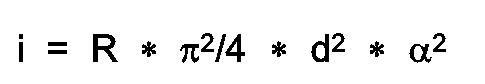
der Strom i der Primär-Korpuskularsonde abnimmt. Hierbei bedeuten - R =
- der Richtstrahlwert der Korpuskularquelle,
- d =
- Sondendurchmesser der Korpuskularsonde
- α =
- zur Erreichung des Sondendurchmessers d zulässiger Aperturwinkel der Objektivlinse.
- Infolgedessen verringert sich auch die emittierte Sekundärstrahlung, so daß sich das Signal-Rauschverhältnis S/R verschlechtert. Zur Aufnahme hochwertiger Bilder mit gutem Signal-Rauschverhältnis S/R müssen daher lange Bildaufnahmezeiten verwendet werden.
- Bei den bekannten Korpuskularstrahlgeräten werden zum Nachweis der Sekundärstrahlung Detektoren eingesetzt, die zwischen der fokussierenden Objektivlinse und der Probe angeordnet sind. Dabei wird die emittierte Sekundärstrahlung durch eine entsprechend vorgespannte Elektrode von der Probe abgesaugt und auf einen Szintillator beschleunigt. Das dort erzeugte Licht wird in einem Fotomultiplier in ein elektrisches Signal umgewandelt und verstärkt. Andere Detektoren verstärken die abgesaugte Sekundärstrahlung direkt, ohne den Umweg über den Szintillator.
- Das Absaugfeld derartiger Anordnungen wirkt sich jedoch nachteilig auf den Primärstrahl aus. Es lenkt einerseits den Primärstrahl ab und bewirkt andererseits eine Sondenaufweitung.
- Die mit besonders feinen Sonden arbeitenden, hochauflösenden Geräte müssen mit kleinem Abstand zwischen Objektivlinse und Probe, d.h. mit sehr kurzen Brennweiten arbeiten, um die Linsenfehler ausreichend klein zu halten. Dies wiederum führt beim Absaugen der Sekundärstrahlung mit herkömmlichen Detektoranordnungen zu weiteren Schwierigkeiten. Zum einen nimmt der Durchgriff der Absaugfeldstärke mit kleiner werdendem Arbeitsabstand ab und zum anderen kommt durch die Nähe des elektrostatischen Fokussierfeldes der Objektivlinse ein weiteres, konkurrierendes Absaugfeld hinzu. Beide Tatsachen verschlechtern das Auffangen und Nachweisen der Sekundärstrahlung.
- Durch Verwendung der mittleren Elektrode der elektrostatischen Objektivlinse als Absaugelektrode (vgl. 'Patent Abstracts of Japan', Band 13, Nr. 184) kann nahezu die gesamte Sekundärstrahlung auf der mittleren Elektrode aufgefangen werden. Ein dort vorhandenes Szintillatormaterial wandelt die Sekundärstrahlung in Lichtpulse um. Dadurch ist es möglich, Abbildungen der Probe mit optimiertem Signal-Rauschabstand S/R in kürzest möglicher Zeit aufzunehmen.
- Mit einer derartigen Anordnung wird zwischen der Objektivlinse und der Probe kein Platz für eine Detektoranordnung benötigt, so daß der Arbeitsabstand und hierdurch die Linsenfehler der Objektivlinse klein gehalten werden können.
- Ein weiterer Vorteil dieser bekannten Anordnung liegt in dem rotationssymmetrischen, elektrostatischen Feld der mittleren Elektrode, das keine negativen Auswirkungen auf den Primärstrahl hat, insbesondere keine unbeabsichtigten Ablenkungen oder Sondenaufweitungen.
- Bei der gattungsbildenden Vorrichtung gemäß 'Patent Abstracts of Japan', Band 13, Nr. 184, besitzen die drei Elektroden der Objektivlinse gleichen Öffnungsdurchmesser. Die als Szintillator ausgebildete mittlere Elektrode ist dabei über Lichtleiter mit dem Detektor verbunden.
- Der Erfindung liegt die Aufgabe zugrunde ein gattungsgemäßes Korpuskularstrahlgerät so auszubilden, daß die am Szintillator durch die Sekundärstrahlung erzeugte Lichtenergie mit möglichst geringen Verlusten zum Detektor übertragen wird.
- Diese Aufgabe wird erfindungsgemäß durch die kennzeichnenden Merkmale der Ansprüche 1 bis 3 gelöst.
- Weitere Merkmale der Erfindung sind Gegenstand der Unteransprüche und werden im Zusammenhang mit der Zeichnung und der folgenden Beschreibung näher erläutert.
- In der Zeichnung zeigen
- Fig.1
- eine schematische Schnittdarstellung eines Korpuskularstrahlgerätes,
- Fig. 2
- eine Schnittdarstellung durch ein erstes Ausführungsbeispiel einer Objektivlinse und einer lichtübertragenden Einheit,
- Fig. 3
- eine Schnittdarstellung durch ein weiteres Ausführungsbeispieleiner Objectivlinse,
- Fig. 4
- eine Schnittdarstellung durch ein weiteres Ausführungsbeispiel einer Objectivlinse.
- In Fig.1 ist ein Korpuskularstrahlgerät 1 schematisch dargestellt. Es enthält eine nicht dargestellte Einrichtung zur Erzeugung eines Korpuskular-Primärstrahls 2, der durch eine elektrostatische Objectivlinse 3 auf eine Probe 4 fokussiert wird. Der Primärsträhl 2 kann dabei je nach Anwendung durch einen Ionenstrahl oder durch einen Elektronenstrahl gebildet werden.
- Die elektrostatische Objectivlinse 3 weist drei Elektroden 3a, 3b und 3c auf, die als ebene Ringscheiben ausgebildet sind. Die drei Elektroden 3a, 3b und 3c sind in Richtung des Primärstrahls 2 hintereinander angeordnet, wobei die Achse des Primärstrahls 2 mit der Achse 3d der Objektivlinse 3 zusammenfällt.
- Eine die Öffnung der mittleren Elektrode 3b umschließende schmale Ringzone dieser Elektrode ist zumindest auf der der Probe 4 abgewandten Seite mit Szintillatormaterial versehen, das einen Szintillator 5 bildet. Über der elektrostatischen Objektivlinse 3 ist ein lichtempfindlicher Detektor 6, wie beispielsweise ein Fotomultuplier, angeordnet, der auf den Szintillator 5 der mittleren Elektrode 3b ausgerichtet ist.
- Der in Fig.1 dargestellte, durch die Objektivlinse 3 fokussierte positive Ionenstrahl 2 erzeugt im Auftreffpunkt A der Probe 4 eine Sekundärstrahlung. Bei der Objektivlinse sind die beiden äußeren Elektroden 3a und 3c auf Masse gelegt, während die mittlere Elektrode 3b ein stark positives Potential aufweist. Dadurch werden die negativen Teilchen der Sekundärstrahlung, wie beispielsweise Elektronen, auf die mittlere Elektrode 3b und damit auf den Szintillator 5 beschleunigt (Zeile 7). Die auf dem Szintillator 5 auftreffende Sekundärstrahlung erzeugt Lichtpulse, die in den Fotomultuplier 6 gelangen (gestrichelte Pfeile 8) und dort in elektrische Signale umgewandelt und verstärkt werden.
- Für die Beschleunigung der Sekundärstrahlung auf den Szintillator 5 wird keine zusätzliche Spannung benötigt, da der Szintillator 5 durch seine Ankoppelung an die mittlere Elektrode 3b ein ausreichend hohes Potential besitzt.
- Da sich der Szintillator 5 innerhalb der Objektivlinse 3 befindet, kann der Arbeitsabstand b zwischen Objektivlinse 3 und Probe 4 klein gehalten werden, so daß hierdurch auch die Linsenfehler gering bleiben. Zudem können durch das rotationssymmetrische Feld der mittleren Elektrode 3b einerseits eine ungewollte Ablenkung und andererseits eine Sondenaufweitung im Auftreffpunkt A vermieden werden.
- In Fig.2 ist die lichtübertragende Einheit durch ein über der Objektivlinse 3 angeordnetes Spiegelsystem 10 verwirklicht. Die im Szintillator 5 erzeugten Lichtpulse werden gemäß den gestrichelten Pfeilen 11 am Spiegelsystem 10 abgelenkt und dem Fotomultiplier 6 zugeführt.
- Außer den bereits oben beschriebenen lichtübertragenden Einheiten, wie Spiegelsystem 10, kann auch ein Linsensystem verwendet werden.
- Bei der in Fig.1 dargestellten Objektivlinse 3 weist die mittlere Elektrode 3b einen kleineren Öffnungsdurchmesser Db auf als die beiden symmetrisch zur mittleren Elektrode 3b angeordneten und ausgebildeten Elektroden 3a und 3c.
- In Fig.3 ist ebenfalls eine planare, elektrostatische Objektivlinse dargestellt, die jedoch einen asymmetrischen Elektrodenaufbau aufweist. Die der Probe zugewandte äußere Elektrode 3′c der Objektivlinse 3′ weist einen kleineren Öffnungsdurchmesser D′c auf als die beiden anderen Elektroden 3′a und 3′b. Der Durchmesser D′b der mittleren Elektrode 3′b ist wiederum kleiner als der Durchmesser D′a der der Probe abgewandten Elektrode 3′a.
- In Fig.4 ist als weiteres Ausführungsbeispiel eine konische elektrostatische Objektivlinse 3˝ dargestellt. Hierbei sind die Elektroden 3˝a, 3˝b und 3˝c der 0bjektivlinse 3˝ als sich in Richtung des Primärstrahles 2 verjüngende Konuselemente ausgebildet.
- Alle Arten von elektrostatischen Objektivlinsen sind denkbar, wie beispielsweise Einzellinsen, flache und konische Bauformen sowie Immersionslinsen.
Claims (7)
- Korpuskularstrahlgerät, wie Ionenstrahlgerät oder Elektronenstrahlgerät, enthaltenda) eine Einrichtung zur Erzeugung eines Korpuskular-Primärstrahls (2),b) eine den Primärstrahl (2) auf eine Probe (4) fokussierende, elektrostatische Objektivlinse (3), die drei in Strahlrichtung hintereinander angeordnete, rotationssymmetrische Elektroden (3a, 3b, 3c) enthält, wobei die Achse des Primärstrahls (2) mit der Achse (3d) der Objektivlinse (3) zusammenfällt,c) eine die auf der Probe (4) am Auftreffpunkt (A) des Primärstrahls (2) emittierte Sekundärstrahlung absaugende Einrichtung,d) einen im Strahlengang der Sekundärstrahlung angeordneten Szintillator (5), der durch die mittlere Elektrode (3b) der Objektivlinse (3) gebildet wird und mit einem lichtempfindlichen Detektor (6) verbunden ist,gekennzeichnet durch folgende Merkmale:e) der Szintillator (5) ist mit dem Detektor (6) über ein Spiegelsystem (10) oder ein Linsensystem verbunden;f) die mittlere Elektrode (3b) der Objektivlinse (3) weist einen kleineren Öffnungsdurchmesser (Db) als die beiden symmetrisch zur mittleren Elektrode (3b) angeordneten und ausgebildeten Elektroden (3a, 3c) auf.
- Korpuskularstrahlgerät, wie Ionenstrahlgerät oder Elektronenstrahlgerät, enthaltenda) eine Einrichtung zur Erzeugung eines Korpuskular-Primärstrahls,b) eine den Primärstrahl auf eine Probe fokussierende, elektrostatische Objektivlinse (3′), die drei in Strahlrichtung hintereinander angeordnete, rotationssymmetrische Elektroden (3′a, 3′b, 3′c) enthält, wobei die Achse des Primärstrahls mit der Achse der Objektivlinse (3′) zusammenfällt,c) eine die auf der Probe am Auftreffpunkt des Primärstrahls emittierte Sekundärstrahlung absaugende Einrichtung,d) einen im Strahlengang der Sekundärstrahlung angeordneten Szintillator (5), der durch die mittlere Elektrode (3′b) der Objektivlinse (3′) gebildet wird und mit einem lichtempfindlichen Detektor verbunden ist,gekennzeichnet durch folgende Merkmale:e) der Szintillator (5) ist mit dem Detektor über ein Spiegelsystem oder ein Linsensystem verbunden;f) die der Probe zugewandte äußere Elektrode (3′c) der Objektivlinse (3′) weist einen kleineren Öffnungsdurchmesser (D′c) als die beiden anderen Elektroden (3′a, 3′b) auf, während die mittlere Elektrode (3′b) einen kleineren Öffnungsdurchmesser (D′b) als die der Probe abgewandte Elektrode (3′a) besitzt.
- Korpuskularstrahlgerät, wie Ionenstrahlgerät oder Elektronenstrahlgerät, enthaltenda) eine Einrichtung zur Erzeugung eines Korpuskular-Primärstrahls (2),b) eine den Primärstrahl (2) auf eine Probe fokussierende, elektrostatische Objektivlinse (3˝), die drei in Strahlrichtung hintereinander angeordnete, rotationssymmetrische Elektroden (3˝a, 3˝b, 3˝c) enthält, wobei die Achse des Primärstrahls (2) mit der Achse der Objektivlinse (3˝) zusammenfällt,c) eine die auf der Probe am Auftreffpunkt des Primärstrahls (2) emittierte Sekundärstrahlung absaugende Einrichtung,d) einen im Strahlengang der Sekundärstrahlung angeordneten Szintillator (5), der durch die mittlere Elektrode (3˝b) der Objektivlinse (3˝) gebildet wird und mit einem lichtempfindlichen Detektor verbunden ist,gekennzeichnet durch folgende Merkmale:e) der Szintillator (5) ist mit dem Detektor übei ein Spiegelsystem oder ein Linsensystem verbunden;f) die Elektroden (3˝a, 3˝b, 3˝c) der Objektivlinse (3˝) sind als sich in Richtung des Korpuskular-Primärstrahls (2) verjüngende Konuselemente ausgebildet.
- Gerät nach Anspruch 1, 2 oder 3, dadurch gekennzeichnet, daß der Korpuskular-Primärstrahl (2) durch einen Ionenstrahl gebildet wird.
- Gerät nach Anspruch 1, 2 oder 3, dadurch gekennzeichnet, daß der Korpuskular-Primärstrahl (2) durch einen Elektronenstrahl gebildet wird.
- Gerät nach Anspruch 1 oder 2, dadurch gekennzeichnet, daß die Elektroden (3a, 3b, 3c; 3′a, 3′b, 3′c) der Objektivlinse (3; 3′) als ebene Ringscheiben ausgebildet sind.
- Gerät nach Anspruch 1, 2 oder 3, dadurch gekennzeichnet, daß eine die Öffnung der mittleren Elektrode (3b, 3′b, 3˝b) umschließende schmale Ringzone der mittleren Elektrode zumindest auf der der Probe abgewandten Seite mit Szintillationsmaterial versehen ist und den Szintillator (5) bildet.
Applications Claiming Priority (2)
| Application Number | Priority Date | Filing Date | Title |
|---|---|---|---|
| DE3938660A DE3938660A1 (de) | 1989-11-21 | 1989-11-21 | Korpuskularstrahlgeraet |
| DE3938660 | 1989-11-21 |
Publications (3)
| Publication Number | Publication Date |
|---|---|
| EP0428906A2 EP0428906A2 (de) | 1991-05-29 |
| EP0428906A3 EP0428906A3 (en) | 1991-11-13 |
| EP0428906B1 true EP0428906B1 (de) | 1995-01-25 |
Family
ID=6393947
Family Applications (1)
| Application Number | Title | Priority Date | Filing Date |
|---|---|---|---|
| EP90120506A Expired - Lifetime EP0428906B1 (de) | 1989-11-21 | 1990-10-25 | Korpuskularstrahlgerät |
Country Status (4)
| Country | Link |
|---|---|
| US (1) | US5061856A (de) |
| EP (1) | EP0428906B1 (de) |
| JP (1) | JP2973136B2 (de) |
| DE (2) | DE3938660A1 (de) |
Families Citing this family (11)
| Publication number | Priority date | Publication date | Assignee | Title |
|---|---|---|---|---|
| DE4000579A1 (de) * | 1990-01-10 | 1991-07-11 | Integrated Circuit Testing | Ionenstrahlgeraet sowie verfahren zur durchfuehrung von potentialmessungen mittels eines ionenstrahles |
| JPH071681B2 (ja) * | 1990-04-19 | 1995-01-11 | 株式会社日立製作所 | 荷電粒子線装置 |
| DE4027062A1 (de) * | 1990-08-27 | 1992-04-23 | Integrated Circuit Testing | Verfahren und anordnung zum testen und reparieren einer integrierten schaltung |
| US5557105A (en) * | 1991-06-10 | 1996-09-17 | Fujitsu Limited | Pattern inspection apparatus and electron beam apparatus |
| EP0518633B1 (de) * | 1991-06-10 | 1997-11-12 | Fujitsu Limited | Apparat zur Musterüberprüfung und Elektronenstrahlgerät |
| US5122663A (en) * | 1991-07-24 | 1992-06-16 | International Business Machine Corporation | Compact, integrated electron beam imaging system |
| GB2314926B (en) * | 1996-07-01 | 1999-08-25 | K E Developments Ltd | Detector devices |
| EP0917178A1 (de) * | 1997-11-17 | 1999-05-19 | ICT Integrated Circuit Testing Gesellschaft für Halbleiterprüftechnik mbH | Detektor für Sekundärkorpuskeln und dessen Anordnung in einem Korpuskularstrahlgerät |
| WO2001059806A1 (en) * | 2000-02-09 | 2001-08-16 | Fei Company | Through-the-lens collection of secondary particles for a focused ion beam system |
| DE10317894B9 (de) | 2003-04-17 | 2007-03-22 | Leo Elektronenmikroskopie Gmbh | Fokussiersystem für geladene Teilchen, Elektronenmikroskopiesystem und Elektronenmikroskopieverfahren |
| DE102010026169B4 (de) * | 2010-07-06 | 2014-09-04 | Carl Zeiss Microscopy Gmbh | Partikelstrahlsystem |
Family Cites Families (9)
| Publication number | Priority date | Publication date | Assignee | Title |
|---|---|---|---|---|
| US3936645A (en) * | 1974-03-25 | 1976-02-03 | Radiologic Sciences, Inc. | Cellularized Luminescent structures |
| KR850001390B1 (ko) * | 1980-07-31 | 1985-09-24 | 니혼 덴시 가부시끼 가이샤 | 2차 전자 검출장치 |
| JPS60212953A (ja) * | 1984-04-06 | 1985-10-25 | Hitachi Ltd | 電子線装置 |
| DE3500903A1 (de) * | 1985-01-12 | 1986-07-17 | Fa. Carl Zeiss, 7920 Heidenheim | Detektor fuer rueckstreuelektronen |
| JPS61190839A (ja) * | 1985-02-19 | 1986-08-25 | Canon Inc | 荷電粒子線装置 |
| DE3703028A1 (de) * | 1987-02-02 | 1988-09-01 | Siemens Ag | Rastermikroskop |
| US4831267A (en) * | 1987-02-16 | 1989-05-16 | Siemens Aktiengesellschaft | Detector for charged particles |
| JP2551984B2 (ja) * | 1988-09-30 | 1996-11-06 | 日本電子株式会社 | 走査電子顕微鏡 |
| US4987311A (en) * | 1989-08-08 | 1991-01-22 | Etec Systems, Inc. | Electron-detector diode biassing scheme for improved writing by an electron beam lithography machine |
-
1989
- 1989-11-21 DE DE3938660A patent/DE3938660A1/de not_active Withdrawn
-
1990
- 1990-10-25 EP EP90120506A patent/EP0428906B1/de not_active Expired - Lifetime
- 1990-10-25 DE DE59008348T patent/DE59008348D1/de not_active Expired - Fee Related
- 1990-11-14 US US07/612,507 patent/US5061856A/en not_active Expired - Lifetime
- 1990-11-16 JP JP2311256A patent/JP2973136B2/ja not_active Expired - Fee Related
Also Published As
| Publication number | Publication date |
|---|---|
| JP2973136B2 (ja) | 1999-11-08 |
| DE3938660A1 (de) | 1991-05-23 |
| EP0428906A2 (de) | 1991-05-29 |
| EP0428906A3 (en) | 1991-11-13 |
| US5061856A (en) | 1991-10-29 |
| DE59008348D1 (de) | 1995-03-09 |
| JPH03173054A (ja) | 1991-07-26 |
Similar Documents
| Publication | Publication Date | Title |
|---|---|---|
| DE112010000743B4 (de) | Detektor und Vorrichtung für einen Strahl geladener Teilchen mit einem solchen Detektor | |
| DE69224506T2 (de) | Elektronenstrahlgerät | |
| DE112014002951B4 (de) | Rasterelektronenmikroskop | |
| DE69525106T2 (de) | Elektron-Detektor mit grosser Akzeptanz für rückgestreute Elektronen für einen Teilchenstrahl-Apparat | |
| DE68928958T2 (de) | Elektronendetektor zur verwendung in einer gasförmigen umgebung | |
| DE2436160C3 (de) | Rasterelektronenmikroskop | |
| DE69924325T2 (de) | Gasgefüllter Rückstreuelektronendetektor für Rasterelektronenmikroskop unter kontrollierter Umgebung | |
| DE112012002811T5 (de) | Ladungsteilchenstrahlvorrichtung | |
| DE112017007822B4 (de) | Rasterelektronenmikroskop | |
| DE112014007154B4 (de) | Ladungsteilchen-Strahlvorrichtung | |
| DE60118070T2 (de) | Partikelstrahlgerät | |
| EP0428906B1 (de) | Korpuskularstrahlgerät | |
| EP0113746B1 (de) | Elektrodensystem für ein gegenfeldspektrometer eines elektronenstrahl-spannungsmessgerätes | |
| DE69115589T2 (de) | Mehrkanal-Ladungsteilchen-Analysator | |
| DE2646472A1 (de) | Elektronenmikroskop | |
| DE112018007534T5 (de) | Einrichtung für strahl geladener teilchen | |
| DE60038007T2 (de) | Teilchenstrahlgerät | |
| DE2705430A1 (de) | Elektrostatischer analysator fuer geladene teilchen | |
| DE69606515T2 (de) | Elektrostatisch-magnetische Linsenanordnung | |
| DE2043749C3 (de) | Raster-Korpuskularstrahlmikroskop | |
| DE2640260C3 (de) | Durchstrahl ungs-Raster-Korpuskularstrahlniikroskop | |
| DE102023106030A1 (de) | Elektronenstrahlmikroskop | |
| DE1204350B (de) | Elektronenmikroskop | |
| EP0917178A1 (de) | Detektor für Sekundärkorpuskeln und dessen Anordnung in einem Korpuskularstrahlgerät | |
| DE112020007005T5 (de) | Vorrichtung zum nachweis von geladene teilchen oder strahlung |
Legal Events
| Date | Code | Title | Description |
|---|---|---|---|
| PUAI | Public reference made under article 153(3) epc to a published international application that has entered the european phase |
Free format text: ORIGINAL CODE: 0009012 |
|
| AK | Designated contracting states |
Kind code of ref document: A2 Designated state(s): DE FR GB IT NL |
|
| PUAL | Search report despatched |
Free format text: ORIGINAL CODE: 0009013 |
|
| AK | Designated contracting states |
Kind code of ref document: A3 Designated state(s): DE FR GB IT NL |
|
| 17P | Request for examination filed |
Effective date: 19920309 |
|
| 17Q | First examination report despatched |
Effective date: 19940615 |
|
| GRAA | (expected) grant |
Free format text: ORIGINAL CODE: 0009210 |
|
| AK | Designated contracting states |
Kind code of ref document: B1 Designated state(s): DE FR GB IT NL |
|
| PG25 | Lapsed in a contracting state [announced via postgrant information from national office to epo] |
Ref country code: IT Free format text: LAPSE BECAUSE OF FAILURE TO SUBMIT A TRANSLATION OF THE DESCRIPTION OR TO PAY THE FEE WITHIN THE PRE;WARNING: LAPSES OF ITALIAN PATENTS WITH EFFECTIVE DATE BEFORE 2007 MAY HAVE OCCURRED AT ANY TIME BEFORE 2007. THE CORRECT EFFECTIVE DATE MAY BE DIFFERENT FROM THE ONE RECORDED.SCRIBED TIME-LIMIT Effective date: 19950125 Ref country code: NL Effective date: 19950125 Ref country code: FR Effective date: 19950125 |
|
| REF | Corresponds to: |
Ref document number: 59008348 Country of ref document: DE Date of ref document: 19950309 |
|
| GBT | Gb: translation of ep patent filed (gb section 77(6)(a)/1977) |
Effective date: 19950222 |
|
| EN | Fr: translation not filed | ||
| NLV1 | Nl: lapsed or annulled due to failure to fulfill the requirements of art. 29p and 29m of the patents act | ||
| RAP2 | Party data changed (patent owner data changed or rights of a patent transferred) |
Owner name: ADVANTEST CORPORATION Owner name: ICT INTEGRATED CIRCUIT TESTING GESELLSCHAFT FUER H |
|
| PLBE | No opposition filed within time limit |
Free format text: ORIGINAL CODE: 0009261 |
|
| STAA | Information on the status of an ep patent application or granted ep patent |
Free format text: STATUS: NO OPPOSITION FILED WITHIN TIME LIMIT |
|
| REG | Reference to a national code |
Ref country code: GB Ref legal event code: 732E |
|
| 26N | No opposition filed | ||
| REG | Reference to a national code |
Ref country code: GB Ref legal event code: 732E |
|
| REG | Reference to a national code |
Ref country code: GB Ref legal event code: 732E |
|
| REG | Reference to a national code |
Ref country code: GB Ref legal event code: IF02 |
|
| PGFP | Annual fee paid to national office [announced via postgrant information from national office to epo] |
Ref country code: GB Payment date: 20060914 Year of fee payment: 17 |
|
| PGFP | Annual fee paid to national office [announced via postgrant information from national office to epo] |
Ref country code: DE Payment date: 20061222 Year of fee payment: 17 |
|
| GBPC | Gb: european patent ceased through non-payment of renewal fee |
Effective date: 20071025 |
|
| PG25 | Lapsed in a contracting state [announced via postgrant information from national office to epo] |
Ref country code: DE Free format text: LAPSE BECAUSE OF NON-PAYMENT OF DUE FEES Effective date: 20080501 |
|
| PG25 | Lapsed in a contracting state [announced via postgrant information from national office to epo] |
Ref country code: GB Free format text: LAPSE BECAUSE OF NON-PAYMENT OF DUE FEES Effective date: 20071025 |