EP0428076B1 - Système de commande pour le réglage de position de dispositifs d'attelage - Google Patents
Système de commande pour le réglage de position de dispositifs d'attelage Download PDFInfo
- Publication number
- EP0428076B1 EP0428076B1 EP90121448A EP90121448A EP0428076B1 EP 0428076 B1 EP0428076 B1 EP 0428076B1 EP 90121448 A EP90121448 A EP 90121448A EP 90121448 A EP90121448 A EP 90121448A EP 0428076 B1 EP0428076 B1 EP 0428076B1
- Authority
- EP
- European Patent Office
- Prior art keywords
- control system
- switch
- algorithm
- actuation
- input switch
- Prior art date
- Legal status (The legal status is an assumption and is not a legal conclusion. Google has not performed a legal analysis and makes no representation as to the accuracy of the status listed.)
- Expired - Lifetime
Links
Images


Classifications
-
- A—HUMAN NECESSITIES
- A01—AGRICULTURE; FORESTRY; ANIMAL HUSBANDRY; HUNTING; TRAPPING; FISHING
- A01B—SOIL WORKING IN AGRICULTURE OR FORESTRY; PARTS, DETAILS, OR ACCESSORIES OF AGRICULTURAL MACHINES OR IMPLEMENTS, IN GENERAL
- A01B63/00—Lifting or adjusting devices or arrangements for agricultural machines or implements
- A01B63/02—Lifting or adjusting devices or arrangements for agricultural machines or implements for implements mounted on tractors
- A01B63/10—Lifting or adjusting devices or arrangements for agricultural machines or implements for implements mounted on tractors operated by hydraulic or pneumatic means
- A01B63/1006—Lifting or adjusting devices or arrangements for agricultural machines or implements for implements mounted on tractors operated by hydraulic or pneumatic means the hydraulic or pneumatic means structurally belonging to the tractor
-
- A—HUMAN NECESSITIES
- A01—AGRICULTURE; FORESTRY; ANIMAL HUSBANDRY; HUNTING; TRAPPING; FISHING
- A01B—SOIL WORKING IN AGRICULTURE OR FORESTRY; PARTS, DETAILS, OR ACCESSORIES OF AGRICULTURAL MACHINES OR IMPLEMENTS, IN GENERAL
- A01B63/00—Lifting or adjusting devices or arrangements for agricultural machines or implements
- A01B63/02—Lifting or adjusting devices or arrangements for agricultural machines or implements for implements mounted on tractors
- A01B63/10—Lifting or adjusting devices or arrangements for agricultural machines or implements for implements mounted on tractors operated by hydraulic or pneumatic means
- A01B63/111—Lifting or adjusting devices or arrangements for agricultural machines or implements for implements mounted on tractors operated by hydraulic or pneumatic means regulating working depth of implements
- A01B63/1117—Lifting or adjusting devices or arrangements for agricultural machines or implements for implements mounted on tractors operated by hydraulic or pneumatic means regulating working depth of implements using a hitch position sensor
Definitions
- the invention relates to a control system for adjusting the position of a hitch, in particular a tractor.
- a control system for adjusting the position of a hitch, in particular a tractor.
- the control system contains actuating means for raising and lowering the towing device, a sensor for detecting an actual position value of the towing device, an operating device that can be set by an operator for setting a position setpoint for the towing device, an input switch that can be set by an operator, and a control unit.
- the control unit for example an electronic control unit or a microprocessor, controls the position of the actuating means as a function of at least the desired position value, the actual position value and the setting of the input switch, wherein a large number of desired working positions of the towing device can be set by adjusting the operating device. With a certain actuation of the input switch, the hitch can only be brought into a limit position.
- a hitch control system known from a John Deere tractor includes a lift shaft operating lever, the movement of which allows the hitch to be raised and lowered under certain conditions and the working depth of the implement to be adjusted.
- This known system also includes a lift / lower switch mounted in the cabin. If this switch is in its "lower” position, the control system regulates the implement depth at a value which corresponds to the working depth set by the operating lever. The control system thus responds to changes in the setting of the operating lever. If the raise / lower switch is in its "upper” position, the setting of the operating lever has no influence on the control, and the towing device and the implement are moved to the outermost upper position.
- the control system blocks the hitch and with it the implement in the current position. If there is a failure of the feedback potentiometer that detects the position of the hitch, then by setting the switch to its "upper” position, the hitch can be caused to move to the outermost upper position, and by setting the switch to the "lower” Position, the hitch can be caused to move to the outermost lower position.
- This known control device also includes a switch mounted outside the cab on the rear of the tractor, near the hitch. This outer switch can be operated to raise the hitch to any position desired by the operator or lower.
- the changeover switch located in the cabin has two switch positions designed as detent positions.
- the outer switch is a three-layer switch that is spring biased to its middle position.
- Another control system used for agricultural tractors for a towing device contains a lifting shaft control button, by means of which the working depth of the implement is set, as well as a lifting / lowering switch with one lifting, one lowering and one neutral position, which can be snapped into each of its three positions.
- This system works similarly to the one described above, provided that the raise / lower switch is in its raised or lowered position. However, if the raise / lower switch is in its neutral, middle position, the control system is unable to work, movement of the towing device is suppressed and the system does not respond to movements of the lifting shaft control button.
- the raise / lower switches are latching switches that remain in the set position until they are deliberately moved out of this position.
- a correct combination of control settings is required to raise or lower the hitch to a desired position using the control lever or button.
- the raise / lower switch must be in its "lower” position, otherwise regulation is not effective due to the position of the control lever. Failure of this switch in the "upper” position can render the control lever ineffective. It is desirable to provide a hitch control system which requires less operator intervention and which has other functional advantages provided by the electronics.
- the object to be achieved with the invention is seen in providing a control system for a towing device of the type mentioned at the beginning with simplified control devices which can be actuated by an operator and which has an improved mode of operation, in particular by using a microprocessor.
- the implement In certain failure conditions, the implement should be able to be moved to a working depth by appropriate handling of the lift / lower switch attached in the cabin.
- the Input switch is a spring-centered switch with at least the following three positions: a lifting position which is assigned to a lifting operation, a working position which is assigned to a controlled tillage operation, and a neutral (middle) position which the switch assumes due to the spring force if it is not actuated .
- the first position can be an upper position and the second position can be a lower position. This assignment is often used in the following, since it is also characteristic of the intended function.
- a control system with such a rocker switch advantageously enables a considerable simplification of the operating functions.
- an operator can bring the hitch into the desired position by operating the control lever and a single operation of the rocker switch.
- the rocker switch is used to control a desired mode of operation and is only briefly brought into one of its unstable positions. Different operating modes can be called up by operating the appropriate switch.
- a position control of the towing device is preferably triggered by a brief actuation of the rocker switch into its working position, which position control is maintained even when the rocker switch returns to its rest position.
- the rocker switch can also be used to cancel an initial locking operating mode of the position control, in which it is not possible for the operating device to influence the position of the towing device.
- This lever lock mode becomes ineffective when the rocker switch is temporarily brought into its working position.
- the locking and commissioning of the position control is preferably only canceled by temporarily operating the switch in its lower working position if the actual position value is above the position setpoint. However, if the actual value is below the target value, the lock remains in place, so that the towing device is not automatically raised when the rocker switch is actuated to ensure occupational safety.
- the control system contains an erasure feature by means of which a response of the control system to an earlier, temporary actuation of the input switch in a first position is suppressed, provided that the input switch is brought into a second position within a certain time interval after this actuation.
- the effect (control commands) of a temporary deflection of the The rocker switch is lifted to one of its unstable positions, provided that the rocker switch subsequently moves to the other unstable position within a certain period of time, for example two seconds.
- the hitch is held in its current position and the position control is suppressed.
- rocker switch If the rocker switch is held in its working position for at least a period of time, for example a second, or if it is brought into the working position a second time, an earlier extinguishing feature is overridden and the system is caused to react as if the rocker switch were only in its second layer has been brought. Switch operations that are pending for less than a certain period of time are ignored.
- the control system preferably contains a locking operating mode in which the position of the towing device cannot be adjusted by actuating the setting of the operating device.
- a locking operating mode in which the position of the towing device cannot be adjusted by actuating the setting of the operating device.
- position control of the towing device is suppressed until the operating device has been moved to one of its extreme positions.
- the lock is only released when the operating lever is in the position that corresponds to the upper or lower position of the hitch.
- rocker switch If the rocker switch has been temporarily moved into its (upper) lifting position and then released again, it automatically returns to its middle position. This triggers a control command from the control system, which generally moves the towing device into its fully raised position, which is set by setting a position limit value adjuster. Furthermore, the lever lock mode is activated to further movements of the hitch suppress. The lever lock mode will continue until the operating lever is moved all the way back to the position that corresponds to the upper position of the hitch (passing through the position of the hitch) or until the operating lever is fully forward to that of the lower position of the Hitch corresponding setting is moved. After unlocking, the position of the hitch can be adjusted by moving the control lever. An additional actuation of the rocker switch is not necessary.
- rocker switch is set to its (upper) lifting position while the lever lock mode is active and the operating lever is above the detected hitch position, the hitch is raised to its top position and the lever lock mode remains in effect.
- the towing device is preferably caused to move into a limit value position if the rocker switch is temporarily moved into one of its unstable positions.
- the hitch can be automatically moved to an upper limit position.
- the limit position is set, for example, by the operator using a limit value setter provided for this purpose, for example a potentiometer.
- the control system contains, according to a further solution according to the invention, a failure mode of operation by means of which adjustment of the towing device remains possible.
- a failure mode of operation by means of which adjustment of the towing device remains possible.
- the hitch cannot be adjusted by the operating lever, it can can be raised and lowered by pressing an input switch, in particular a rocker switch, up or down. This hitch movement stops when the rocker switch is released.
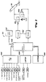
- a device hitch 26 such as a conventional three-point hitch, contains lower links 28 as tension members, which are connected to lifting arms 30 via lifting spindles 32.
- the lifting arms 30 are in turn connected to the lifting shaft 24 in such a way that they ensure a simultaneous and identical movement and can be raised and lowered by two hydraulic lifting shaft cylinders 34 fastened in parallel.
- a pull rod 36 extends rearward beyond the housing 20.
- the tractor 10 and the hitch 26 are only given as examples. It will be apparent to those skilled in the art that the invention can also be used with other types of tractors and towbars.
- the present invention can be used with an articulated four-wheel drive tractor, with a front-wheel drive wide-track tractor, or with a front-mounted hitch.
- An attachable tillage implement (not shown), such as a plow or a chisel plug, can be attached to the lower links 28 in a conventional manner.
- a towing device (not shown) can be coupled to the pull rod 36.
- a tensile force sensor 38 is interposed in a connector, not shown, which is used in place of the hydraulic tensile force sensing cylinder of a conventional hydromechanical trailer system in order to detect the tensile force that is transmitted from the attachable implement to the lower links 28.
- separate left and right tensile force sensors can be used in the left and right lower links 28, the signals of which are electronically combined or averaged.
- the pulling force can be detected by a pulling force sensor which is interposed in the pull rod 36 or is located in a T-piece which connects the pulling members.
- a pulling force sensor which is interposed in the pull rod 36 or is located in a T-piece which connects the pulling members.
- Suitable known tensile force sensor can be used, such as the model GZ-10, which is manufactured by Revere Corporation of America.
- Hydraulic fluid flow to and from cylinder 34 or to and from a remote cylinder, not shown, on a towed or semi-attachable implement is controlled by a pair of magnetically actuated electrohydraulic flow control valves 42a and 42b which receive electrical control signals provided by controller 50 be generated.
- Flow control valves 42 may be those described in U.S. Patent 4,799,645, the disclosure of which is incorporated by reference.
- An operator-adjustable control lever 52 communicates with a lever position transducer 54 (e.g., a potentiometer) that generates a command signal that indicates a desired hitch location or tension, or a load / depth / or mix control potentiometer 56 corresponds to a combination of the two.
- a lever position transducer 54 e.g., a potentiometer
- An electrical signal corresponding to an upper limit position is supplied by a potentiometer 51 that can be adjusted by an operator.
- the lever 52 is slidable within a slot, not shown. The ends of this slot act as lower or upper mechanical stops which mechanically limit the position of the operating lever and thus limit the signal of the potentiometer 54.
- a lowering speed potentiometer 58 adjustable by an operator, is also provided.
- a position transducer 60 for example a conventional rotary potentiometer, generates a position signal which reflects the position of the lifting shaft 24 that is actually detected.
- a position feedback signal could also be obtained from the lift shaft cylinder 34 or from a remote lift cylinder if the cylinder in question contains a position transducer, such as that described in U.S. Patent 3,726,191.
- a two-pole double lifting / lowering switch 70 can be fastened outside the tractor cabin in the vicinity of the hitch device 26, so that an operator can raise and lower the hitch device from outside the tractor cabin.
- a calibration switch 72 is mounted within the tractor cabin; however, it is not the subject of the present invention.
- the control system also includes an in-cab raise / lower switch 80.
- this is a spring centered three position rocker switch 80 as shown in FIG . It includes a lifting port 82, a lowering port 84, a common or neutral port 86 and a tiltable contact element 88.
- a pair of centering springs 90 return the contact member 88 to its central position in which it is spaced from the lifting port 82 and the lowering port 84 is provided that it is not manually kept in contact with one of the two connections 82 or 84.
- the sink terminal 84 is grounded through a resistor.
- the lifting terminal 82 and the common terminal 86 are connected to a voltage source and an A / D converter 502 (analog-digital converter) via a chain conductor 92 formed from impedances in such a way that the voltage which is applied from the switch 80 to the A / D converter 502 is transmitted, is characteristic of the position of the switch 80.
- a / D converter 502 analog-digital converter
- the control unit 50 preferably contains an analog-digital converter 502, a self-holding one Switching element (latch) 504, an electrically erasable, programmable read-only memory (EEPROM) 506, a microprocessor 508 with a timer 510 and a pair of valve actuators 512.
- the valve actuators 512 can be conventional pulse-duration-modulated valve current drivers. However, they are preferably those as described in US Pat. No. 4,964,014.
- the analog signals from the sensors 38 or potentiometers 51, 54, 56, 58 and 60 and the switch 80 are connected to the microprocessor 508 via the A / D converter 502.
- the self-holding switching element 504 connects the external raise / lower switch 70 and the calibration switch 72 to the microprocessor 508.
- the calibration data which are used in a calibration process are stored in the EEPROM 506.
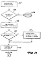
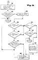
- the rocker switch subroutine is periodically carried out by the control unit 50, as can be seen from the logic flow diagrams of FIGS. 3a to 3l.
- Control unit 50 preferably executes a locking algorithm as described in U.S. Patent No. 4,837,691 and a main control program for the hitch as described in U.S. Patent 4,518,044. Both patents are referred to for their disclosure.
- the control unit 50 executes the rocker switch subroutine every time the main program is executed.
- step 102 The subroutine for a rocker switch with three positions is started with step 100 each time the main program is triggered. If a FAILURE bit was previously set to indicate a failure state of the rocker switch 80, step 102 resets the algorithm to the main program via step 104. If the FAILURE bit has not been set, the algorithm continues with steps 106 to 110. Step 106 provides a two-second timer step back. Steps 108 and 110 clear a two-second timer bit (SECTWO bit), ie set it to zero or enable it, if the two-second timer had expired. Otherwise, step 108 directs the algorithm to step 112, which determines and stores the current state of the rocker switch 80 as an A / D value and leads the algorithm to step 114.
- SECTWO bit two-second timer bit
- step 114 directs the algorithm to step 122 if an error condition occurs due to a grounded connection.
- step 116 directs the algorithm to step 126 when the rocker switch 80 is now in the down position.
- step 118 directs the algorithm to step 180 when the rocker switch 80 is now in the middle position.
- step 120 directs the algorithm to step 200 when the rocker switch 80 is now in the up position.
- step 120 directs the algorithm to step 122 if one of the switch ports has a high voltage (open circuit) fault condition. The algorithm continues with step 122 if such an error condition has occurred.
- step 122 directs the algorithm to step 124 if the error condition determined in step 122 continues for more than 0.2 seconds. If the error condition lasts at most 0.2 seconds, step 122 returns to the main program. Step 124 sets a FAILURE bit that contains a serious error, generates a diagnostic message, clears all memory contents that indicate the operating state of the rocker switch 80 relate and makes a lever lock logic effective.
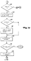
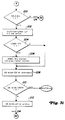
- step 126 which is achieved when the rocker switch 80 is in its lower position, directs the algorithm to the failure state logic of step 124, provided that a start-up bit (PWRUP bit) was set to 1, which indicates that rocker switch 80 was in the down position when the system was turned on and powered on. If the PWRUP bit was not set to 1, step 126 directs the algorithm to step 128, which sets a down timer for 0.2 seconds. This will reset the error timer used in step 122. Then, through steps 130 and 132, a UPDNSL bit is set and a counter is set to a time interval of 100 milliseconds when the rocker switch 80 was in the down position for the first time during the algorithm.
- PWRUP bit start-up bit
- Steps 134 and 136 return the algorithm to the main program if the rocker switch 80 has not been held in its down position for at least 100 milliseconds. If the rocker switch remains in its lower position for at least 100 milliseconds, step 136 directs the algorithm to step 138, which increments the 100 millisecond counter and directs the algorithm to step 140.
- step 140 directs the algorithm to step 142 if the lever position converter 54 of the operating lever 52 has failed.
- Steps 144 and 146 direct the algorithm to step 142 if the position converter 60 has failed and the operating lever 52 has not been moved into one of the two end positions.
- Step 142 sets a FULLDOWN bit, enables the other modes of the rocker switch 80, and unlocks the control lever logic (or disengages the lever lock logic) and then returns control to the main program. If step 146 determines that the lever 52 has been moved to one of the two end positions, then step 146 directs the algorithm to the failure logic of step 124. If neither the lever position transducer 54 nor one of the feedback potentiometer 60 has failed, the algorithm proceeds from step 144 to 148 further.
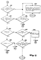
- Step 148 determines whether the delete feature was previously called by setting a LOKBIT value. If the delete feature was invoked, step 148 directs the algorithm to step 150. Step 150 directs the algorithm to step 158 if this is the second time that switch 80 has been placed in the (lower) down position. Otherwise, step 150 directs the algorithm to step 154. Step 154 directs the algorithm to step 158 if the rocker switch 80 is held in its down position for more than one second. Otherwise the algorithm returns to the main program.
- step 148 determines whether the erase feature (LOKBIT bit) was not called, step 148 directs the algorithm to step 152. Step 152 determines whether a sink mode was selected by checking the value of a DOWN bit. If a sink mode was selected, step 152 directs the algorithm to step 158. If the sink mode was not selected, step 152 directs the algorithm to step 172.
- step 158 the algorithm occurs in step 158 when the rocker switch 80 is in its down position and this down position was already selected by setting the DOWN bit earlier, as done in steps 164 and 166, or if a delete feature was queried according to steps 148, 150 and 154.
- Step 158 sets a two-second timer and a slew timer and issues a SLEW bit free.
- the SLEW bit indicates that lever 52 has remained in one of the two limit positions for the past 200 milliseconds.
- step 160 directs the algorithm to step 162, through which the algorithm is directed to step 124 to set a FAILURE bit when the operating lever 52 was moved to one of its end positions (check of the SLEW bit). Otherwise, step 162 directs the algorithm to step 166, which sets a DOWN bit and a LOKBIT bit. Step 166 then returns control to the main program, which responds to protect the hitch from moving according to the setting of the operating lever 52 when the rocker switch 80 is in the down position and the position set point is above the actual position value.
- step 160 directs the algorithm to step 164, which sets a DOWN bit. Then, if step 168 determines that the operating lever 52 has been moved to one of its stop positions, step 168 directs the algorithm to the logic of step 124. Otherwise, step 168 directs the algorithm to step 170, which releases the LOKBIT bit (deletion feature becomes ineffective) , the operating lever 52 takes effect and the control returns to the main program. If the rocker switch 80 is in its lower position and the position setpoint is below the actual position value, the main program moves the towing device down into the position required by the operating lever 52.
- step 172 the algorithm is directed to step 172 (FIG. 3g) if the lowering mode has not been done beforehand was selected.
- Step 172 directs the algorithm to step 158 if the two-second timer reset in step 106 has expired. Therefore, this causes the lowering mode to be selected without checking the previous switch selection if more than two seconds have elapsed since the last switch was pressed.
- step 172 directs the algorithm to step 174 which checks the state of a UP bit which indicates that the rocker switch 80 was previously in the up position. If no UP bit has been set, the sink mode is selected and the algorithm proceeds to step 158.
- step 174 directs the algorithm to step 176, by which it is determined whether the Rocker switch 80 was held in the lower position for more than one second. If so, step 176 causes the algorithm to proceed to step 158. If the rocker switch 80 is not held in its lower position for at least two seconds, step 176 directs the algorithm to step 178, where a LOKBIT bit is set and the delete feature is called.
- Step 118 in FIG. 3b directs the algorithm to step 180 of FIG. 3h when the rocker switch 80 is in its middle position.
- Step 180 sets a failure counter to a two second period and a CENTER bit indicating that the rocker switch 80 is in the middle position.
- the algorithm then continues with step 182, which determines whether the rocker switch 80 has been in its central position for at least 100 milliseconds. If this is not the case, the algorithm returns to the main program. Otherwise, step 182 directs the algorithm to step 184.
- Step 184 clears a UPDNSL bit, indicating that the rocker switch 80 has been in its central position for more than 100 milliseconds.
- Steps 186 and 188 direct the algorithm to step 194 if a failure has been detected on the control lever 52 and / or on the position feedback sensor 60.
- Steps 194 and 196 direct the algorithm to step 198 if the rocker switch 80 has recently been in the up position or previously in the down position.
- Step 198 clears all state information of the rocker switch 80, calls up the lever locking logic in order to prevent the hitch 26 from moving as a function of an adjustment of the operating lever 52, and returns the algorithm to the main program. However, if rocker switch 80 was not in the up or down position recently, steps 194 and 196 return control directly to the main program.
- Step 190 determines whether the operating lever 52 has been fully retracted (bottom position) for at least 100 milliseconds. If so, the algorithm proceeds to step 192 where the UP mode is cleared, the lever logic is released (the lever lock logic is disabled) and control is returned to the main program. If step 192 is carried out, the main program reacts by moving the hitch 26 as a function of an adjustment of the operating lever 52 so that the hitch 26 follows the operating lever 52. However, if the operating lever 52 has not been fully retracted for 100 milliseconds, step 190 performs the Control returns to the main program without unlocking the control lever 52. In this way, the main program responds by suppressing movement of the hitch 26 until the operating lever 52 is moved all the way back or to a position which corresponds to the position of the hitch 26.
- Step 120 in FIG. 3b directs the algorithm to step 200 of FIG. 3i when the rocker switch 80 is in its upper position.
- Step 200 directs the algorithm to the failure logic of step 124 if the rocker switch 80 was in its upper position when the system was initially turned on. Otherwise, the algorithm proceeds to step 202, which resets the down timer to a time period of 0.2 seconds.
- Step 204 then directs the algorithm to step 208 if the UPDNSL bit was previously set to 1, indicating that the rocker switch 80 was previously in its up position. Otherwise, step 204 directs the algorithm to step 206, which sets the UPDNSL bit to indicate that this is the first time that rocker switch 80 has been in its up position. Step 206 also sets a timer to 100 milliseconds.
- Step 208 increments the timer. Then step 210 returns control to the main program if the 100 millisecond timer has not yet expired. If, on the other hand, it has expired, step 210 directs the algorithm to step 212, which increments the timer, and then to step 214. At this point, it is clear that the rocker switch 80 has been in its upper position for at least 100 milliseconds .
- step 214 directs the algorithm to step 220 if the lever position converter fails 54 was found.
- Step 220 sets the UP bit, unlocks the control lever logic, clears the stored states of the rocker switch 80 and returns control to the main program. This enables the towing device 26 to be actuated by tilting the rocker switch 80 into one of its unstable positions.
- step 216 If there is no failure of the lever position transducer 54, the algorithm proceeds to step 216, by which it is checked whether there is a failure of the position feedback sensor 60. If this is the case, the algorithm proceeds to step 218. Step 218 then directs the algorithm back to step 220 if the operating lever 52 has not been moved to one of its end positions. Otherwise, step 218 directs the algorithm to the failure logic of step 124.
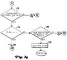
- step 222 determines whether the LOKBIT bit has been set beforehand. This was done, for example, by step 248, which is carried out when the rocker switch 80 was first brought into its upper position and later into its lower position. If the LOKBIT bit has been set to 1, step 222 directs the algorithm to step 224, in which it is determined whether this is the second time that the rocker switch 80 has been moved to its upper position. If so, the algorithm proceeds to step 226, which clears the LOKBIT bit and the UP bit and directs control to step 134.
- step 224 directs the algorithm to step 230. If the rocker switch 80 remains in its upper position for at least one second, step 230 also directs the algorithm to step 226 and clears the LOKBIT bit and the UP bit and directs the algorithm to step 234. On the other hand, if the rocker switch 80 has not been in the upper position for at least one second, the algorithm returns to the main program. Starting from step 222, this directs the algorithm to step 228 if the LOKBIT bit was not previously set. Step 228 determines whether the UP bit was previously set.
- step 228 directs the algorithm to step 242 (FIG. 31).
- step 242 directs the algorithm to step 244 if less than two seconds have passed since the last switch was actuated.
- Step 244 determines if the DOWN bit was previously set, which means that the rocker switch 80 was in its down position, but then moved to its up position within the past two seconds. If so, step 244 directs the algorithm to step 246. If the rocker switch 80 has been in its upper position for less than one second, step 246 directs the algorithm to step 248, which sets the LOKBIT bit, thereby causing the Lever lock logic is invoked and the influence of any previous actuation of rocker switch 80 is cleared. The control then returns to the main program.
- step 246 directs the algorithm to step 234 (FIG. 3k).
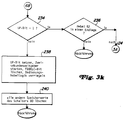
- step 234 the algorithm proceeds to step 234 if the DOWN bit was previously set.
- step 234 branches to step 238 if the UP bit has not been set.
- Step 238 sets a UP bit, sets the lever lock logic, and sets the lock position all the way up, causing the hitch to be raised.
- step 234 is performed when the rocker switch 80 has been held in its up position for at least one second, when the rocker switch 80 has been tilted a second time, or when the rocker switch 80 has been temporarily moved to its up position without it was previously in the lower position.
- Step 234 determines whether the UP bit has been previously set. If the UP bit was not previously set, the algorithm proceeds to step 238, which sets the UP bit, starts the two-second timer for the delete feature, and sets an FDBKLC bit to zero. This causes the hitch to be moved fully to the raised position by the main program.
- Step 238 also invokes the lever lock logic, which prevents the main program from adjusting the hitch 26 depending on the position of the operating lever 52.
- Step 238 then directs the algorithm to step 240, which clears the various operating values of the rocker switch 80 and then returns the algorithm to the main program.
- step 234 directs the algorithm to step 236 in the next pass through the algorithm loop. If the operating lever 52 has been moved to one of its end positions, step 236 aligns the algorithm to the failure logic of step 124. If the operating lever 52 has not been moved into an end position, step 236 returns control to the main program.
- the towing device 26 can be raised by a single occasional tilting of the rocker switch 80 and then by the operating lever 52 a working position can be lowered without the rocker switch 80 having to be operated again because the rocker switch 80 automatically returns to its central position when released.
- Steps 118 and 180-192 allow the hitch to be moved in response to control lever 52 when rocker switch 80 is in its center position and control lever 52 has been moved to its very bottom position.
- Steps 174-178 and 244-248 cancel the influence of previous actuation of rocker switch 80 if rocker switch 80 was actuated in a different manner later, within two seconds of the first actuation.
- Steps 130-136 cause the system to ignore switch operations unless they have existed for at least a period of time.
- Steps 122, 124, 166, 178, 198, 232, 238 and 248 cause the lever lock mode to operate which prevents movement of the hitch 26 in response to actuation of the control lever 52.
- Steps 140-146 and 214-220 respond to a failure condition and allow the hitch 26 to be moved to any desired position by actuating the rocker switch 80, whereas the rocker switch 80 typically only moves the hitch to its extreme upper or lower position can be moved.
Claims (10)
- Système de commande pour régler la position d'un dispositif d'attelage (26), notamment d'un tracteur, avec des moyens d'actionnement (34) pour relever et abaisser le dispositif d'attelage (26), avec un capteur (38, 60) pour enregistrer une valeur effective de position du dispositif d'attelage (26), avec un dispositif de manoeuvre (52, 54), réglable par un opérateur, pour régler une valeur de consigne de position pour le dispositif d'attelage (26), avec un commutateur d'entrée (80) réglable par un opérateur, et avec une unité de commande (50) qui commande les moyens d'actionnement (34) au moins en fonction de la valeur de consigne de position, de la valeur effective de position et du réglage du commutateur d'entrée (80), l'unité de commande (50) comprenant d'une part des moyens permettant de déplacer le dispositif d'attelage (26) seulement dans une position limite lors d'un actionnement déterminé du commutateur d'entrée (80), et comprenant d'autre part des moyens permettant de régler le dispositif d'attelage (26), en fonction de la valeur de consigne de position, dans une multiplicité de positions de travail souhaitées, caractérisé en ce que le commutateur d'entrée est un commutateur (80) centré par ressort avec au moins les trois positions suivantes : une position de levage, qui est associée à un fonctionnement de relevage, une position de travail, qui est associée à un fonctionnement de travail dirigé du sol, et une position neutre, que prend le commutateur (80) sous l'action de la force de ressort lorsqu'il n'est pas actionné, et en ce que l'unité de commande (50) comprend des moyens qui autorisent, même dans la position neutre du commutateur (80), le réglage d'une position de travail du dispositif d'attelage (26) en fonction d'un actionnement du dispositif de manoeuvre (52).
- Système de commande selon la revendication 1, caractérisé en ce qu'un actionnement temporaire du commutateur (80) dans sa position de travail permet de déclencher un réglage de la profondeur de travail avec une valeur de consigne de position allouable par le dispositif de manoeuvre (52, 54), dans la mesure où la valeur effective de position est supérieure à la valeur de consigne de position.
- Système de commande selon la revendication 1 ou 2, caractérisé par des moyens qui interdisent la réponse du système de commande à un actionnement temporaire antérieur du commutateur d'entrée (80) dans une première position, dans la mesure où le commutateur d'entrée (80) est amené dans une seconde position au cours d'un intervalle de temps déterminé suivant cet actionnement.
- Système de commande selon l'une quelconque des revendications 1 à 3, caractérisé par des moyens pour interdire la réponse du système de commande à un actionnement du commutateur d'entrée (80) dans la mesure où l'actionnement ne se prolonge pas pendant au moins un intervalle de temps déterminé.
- Système de commande selon la revendication 3 ou 4, caractérisé par des moyens qui lèvent l'interdiction et permettent une réponse à un actionnement du commutateur d'entrée (80) dans la mesure où le commutateur d'entrée a été amené deux fois successivement dans la même position instable.
- Système de commande selon l'une quelconque des revendications 1 à 5, caractérisé par un mode de fonctionnement de verrouillage, dans lequel le système de commande coopère avec les moyens d'actionnement (34) de manière à interdire le déplacement du dispositif d'attelage (26) en fonction d'un réglage du dispositif de manoeuvre (52, 54).
- Système de commande selon l'une quelconque des revendications 1 à 6, caractérisé en ce qu'à la suite d'un déplacement du commutateur (80) dans une de ses positions instables, le réglage de la position du dispositif d'attelage (26) en fonction du dispositif de manoeuvre (52) est interdit jusqu'à ce que le dispositif de manoeuvre (52) ait été amené dans une de ses positions extrêmes.
- Système de commande selon l'une quelconque des revendications 1 à 7, caractérisé par des moyens qui engendrent le déplacement du dispositif d'attelage (26) à une valeur limite dans le mesure où le commutateur d'entrée (80) est déplacé temporairement dans une de ses positions instables.
- Système de commande selon la revendication 8, caractérisé en ce qu'un actionnement temporaire du commutateur d'entrée (80) dans sa position de levage permet un déplacement automatique du dispositif d'attelage (26) jusqu'à une position limite supérieure.
- Système de commande selon l'une quelconque des revendications 1 à 9, caractérisé par des moyens qui réagissent à une condition de défaillance et permettent le déplacement du dispositif d'attelage (26) dans une position de travail par l'actionnement du commutateur d'entrée (80).
Priority Applications (1)
| Application Number | Priority Date | Filing Date | Title |
|---|---|---|---|
| EP93118410A EP0590692B1 (fr) | 1989-11-13 | 1990-11-09 | Système de commande pour le réglage de position de dispositifs d'attelage |
Applications Claiming Priority (2)
| Application Number | Priority Date | Filing Date | Title |
|---|---|---|---|
| US435861 | 1989-11-13 | ||
| US07/435,861 US4969527A (en) | 1989-11-13 | 1989-11-13 | Hitch control system |
Related Child Applications (1)
| Application Number | Title | Priority Date | Filing Date |
|---|---|---|---|
| EP93118410.5 Division-Into | 1990-11-09 |
Publications (2)
| Publication Number | Publication Date |
|---|---|
| EP0428076A1 EP0428076A1 (fr) | 1991-05-22 |
| EP0428076B1 true EP0428076B1 (fr) | 1994-07-13 |
Family
ID=23730113
Family Applications (3)
| Application Number | Title | Priority Date | Filing Date |
|---|---|---|---|
| EP90121448A Expired - Lifetime EP0428076B1 (fr) | 1989-11-13 | 1990-11-09 | Système de commande pour le réglage de position de dispositifs d'attelage |
| EP93118410A Expired - Lifetime EP0590692B1 (fr) | 1989-11-13 | 1990-11-09 | Système de commande pour le réglage de position de dispositifs d'attelage |
| EP96100800A Expired - Lifetime EP0714592B1 (fr) | 1989-11-13 | 1990-11-09 | Système de commande pour le réglage de position de dispositifs d'attelage |
Family Applications After (2)
| Application Number | Title | Priority Date | Filing Date |
|---|---|---|---|
| EP93118410A Expired - Lifetime EP0590692B1 (fr) | 1989-11-13 | 1990-11-09 | Système de commande pour le réglage de position de dispositifs d'attelage |
| EP96100800A Expired - Lifetime EP0714592B1 (fr) | 1989-11-13 | 1990-11-09 | Système de commande pour le réglage de position de dispositifs d'attelage |
Country Status (5)
| Country | Link |
|---|---|
| US (1) | US4969527A (fr) |
| EP (3) | EP0428076B1 (fr) |
| JP (1) | JP3058441B2 (fr) |
| CA (1) | CA2029009C (fr) |
| DE (3) | DE59010844D1 (fr) |
Families Citing this family (35)
| Publication number | Priority date | Publication date | Assignee | Title |
|---|---|---|---|---|
| US5398766A (en) * | 1990-04-24 | 1995-03-21 | Kabushiki Kaisha Komatsu Seisakusho | Device for controlling height of blade of tracked vehicle |
| US5240079A (en) * | 1990-06-04 | 1993-08-31 | A.I.L., Inc. | Guidance control system for farm tractor/implement combination having improved turnaround capability |
| US5190111A (en) * | 1991-06-03 | 1993-03-02 | Ford New Holland, Inc. | Hitch positioning with slip override control and calibrated wheel speed for determining slip |
| US5320186A (en) * | 1991-06-03 | 1994-06-14 | Ford New Holland, Inc. | Draft control system with closed loop drop/raise rate control |
| US5143159A (en) * | 1991-06-03 | 1992-09-01 | Ford New Holland, Inc. | Draft control system with dual mode draft sensitivity |
| US5291407A (en) * | 1991-06-03 | 1994-03-01 | Ford New Holland, Inc. | Draft control system with safety disconnect |
| US5231892A (en) * | 1992-07-20 | 1993-08-03 | Deere & Company | Hitch control interface assembly |
| GB9220732D0 (en) * | 1992-10-01 | 1992-11-11 | Massey Ferguson Sa | Implement linkage control system |
| DE4235797C2 (de) * | 1992-10-23 | 1994-12-08 | Deere & Co | Kraftfahrzeug mit Hubgerüst |
| US5421416A (en) * | 1993-09-08 | 1995-06-06 | Case Corporation | Hitch assembly control system |
| DE4428824C2 (de) * | 1994-08-16 | 1998-05-07 | Deere & Co | Steuereinrichtung zur Ansteuerung von Steuergeräten eines Arbeitsfahrzeuges |
| US5684691A (en) * | 1995-04-17 | 1997-11-04 | Case Corporation | Method and apparatus for controlling draft of an agricultural implement |
| US5884204A (en) * | 1996-04-16 | 1999-03-16 | Case Corporation | Active roadability control for work vehicles |
| US6041867A (en) * | 1996-08-09 | 2000-03-28 | Case Corporation | Hitch initialization control system |
| DE19754233B4 (de) | 1997-12-06 | 2005-01-13 | Deere & Company, Moline | Steuereinrichtung für Zapfwellen |
| US6016875A (en) * | 1998-02-10 | 2000-01-25 | Case Corporation | Gain adaptation control for hydraulic systems |
| US6076611A (en) * | 1998-12-17 | 2000-06-20 | Agco Corporation | Implement mounted depth control system |
| US6134494A (en) * | 1999-04-20 | 2000-10-17 | Case Corporation | Automatic power takeoff control system |
| US6230817B1 (en) | 1999-08-10 | 2001-05-15 | Case Corporation | Hitch assembly for a work vehicle |
| US6076612A (en) * | 1999-08-31 | 2000-06-20 | Case Corporation | Transition from position to draft mode controlled by hitch position command and feedback |
| DE19951392A1 (de) * | 1999-10-26 | 2001-05-03 | Schaeffler Waelzlager Ohg | Vorrichtung zur drehfesten Kopplung und zur Veränderung der relativen Drehlage zweier koaxial um eine Drehachse drehbarer Gehäuse |
| US6216072B1 (en) * | 1999-11-23 | 2001-04-10 | Deere & Company | Hitch control system with adjustable slip response |
| US6935434B1 (en) * | 2004-03-12 | 2005-08-30 | Deere & Company | Hitch control system with spring centered control lever |
| US20050248123A1 (en) * | 2004-05-10 | 2005-11-10 | Symington Owen D | Automatic swinging drawbar system |
| US7168229B1 (en) * | 2005-07-14 | 2007-01-30 | Cnh America Llc | Drop rate control for agricultural header |
| US7408450B2 (en) * | 2005-07-15 | 2008-08-05 | Cnh America Llc | Steering wheel direction indicator for neutral start |
| US20100106344A1 (en) * | 2008-10-27 | 2010-04-29 | Edwards Dean B | Unmanned land vehicle having universal interfaces for attachments and autonomous operation capabilities and method of operation thereof |
| US8406966B2 (en) | 2011-01-13 | 2013-03-26 | Husco International, Inc. | Draft control method for operating an earth moving machine |
| DE102011101714A1 (de) * | 2011-05-17 | 2012-11-22 | Robert Bosch Gmbh | Verfahren einer elektrohydraulischen Hubwerksregelung und Bedieneinheit für eine elektrohydraulische Hubwerksregelung |
| JP5882066B2 (ja) * | 2012-01-19 | 2016-03-09 | 日立建機株式会社 | 作業車両の制御装置 |
| WO2014093788A1 (fr) * | 2012-12-14 | 2014-06-19 | Eaton Corporation | Système et procédés de levage et d'abaissement contrôlés d'une charge |
| US9989986B2 (en) * | 2013-03-12 | 2018-06-05 | Cnh Industrial America Llc | Hitch position encoder with reference indicator for agricultural work vehicle |
| GB201413546D0 (en) * | 2014-07-31 | 2014-09-17 | Agco Int Gmbh | Vehicle control system |
| JP6791827B2 (ja) * | 2017-09-29 | 2020-11-25 | 株式会社小松製作所 | 作業車両及び作業車両の制御方法 |
| US11327512B1 (en) * | 2020-10-22 | 2022-05-10 | Zoomlion Heavy Industry Na, Inc. | Hydraulic lockout lever failure detection system |
Family Cites Families (19)
| Publication number | Priority date | Publication date | Assignee | Title |
|---|---|---|---|---|
| DE1198103B (de) * | 1962-08-11 | 1965-08-05 | Kloeckner Humboldt Deutz Ag | Steuereinrichtung fuer eine durch hydraulische Mittel angetriebene Hebevorrichtung von an land-wirtschaftlichen Schleppern befestigten Boden-bearbeitungsgeraeten |
| US3299224A (en) * | 1966-01-07 | 1967-01-17 | Boyne Products Inc | Self-centering toggle switch with improved actuator contact structure |
| US4132273A (en) * | 1977-06-30 | 1979-01-02 | International Harvester Company | Tractor hitch control system having safety features |
| US4133993A (en) * | 1977-07-28 | 1979-01-09 | General Electric Company | Momentary contact switch with compensating spring |
| US4343365A (en) * | 1980-07-07 | 1982-08-10 | Ford Motor Company | Electrically operated hydraulic power lift system |
| JPS5826923A (ja) * | 1981-08-11 | 1983-02-17 | Matsushita Electric Ind Co Ltd | 燃焼機器の制御装置 |
| CA1196998A (fr) * | 1981-10-22 | 1985-11-19 | James M. Sakundiak | Regulateur electronique automatique d'elevation et de penetration |
| US4518044A (en) * | 1982-03-22 | 1985-05-21 | Deere & Company | Vehicle with control system for raising and lowering implement |
| US4495577A (en) * | 1982-08-06 | 1985-01-22 | Deere & Company | Model reference adaptive implement control |
| US4508176A (en) * | 1982-11-22 | 1985-04-02 | Deere & Company | Vehicle with control system having operator-actuable switch for storing parameter signal value to control vehicle-connected implement raising and lowering structure |
| DE3316305C2 (de) * | 1983-05-04 | 1986-09-04 | Mannesmann Rexroth GmbH, 8770 Lohr | Schaltungsanordnung zum Steuern eines von einem Schlepper gezogenen, mittels eines Hubzylinders der Höhe nach verstellbaren Anbaugeräts |
| US4503916A (en) * | 1983-06-06 | 1985-03-12 | Deere & Company | Hybrid hitch control system |
| US4677542A (en) * | 1984-02-10 | 1987-06-30 | Deere & Company | Self-tuning regulator implement control |
| AU569362B2 (en) * | 1984-02-10 | 1988-01-28 | Deere & Company | Self-tuning regulator implement control |
| FR2568087B1 (fr) * | 1984-07-24 | 1987-03-20 | Defrancq Hubert | Dispositif de commande de la position d'un systeme de relevage d'outil agricole |
| JPH0728568B2 (ja) * | 1986-04-10 | 1995-04-05 | セイレイ工業株式会社 | 作業機昇降制御装置における昇降動作自己保持装置 |
| EP0251529B1 (fr) * | 1986-06-14 | 1991-01-30 | Massey-Ferguson Services N.V. | Système de contrôle d'attelage d'un tracteur |
| US4837691A (en) * | 1987-05-27 | 1989-06-06 | Deere & Company | Hitch control system with start-up lock-out |
| JPH0340173Y2 (fr) * | 1987-08-01 | 1991-08-23 |
-
1989
- 1989-11-13 US US07/435,861 patent/US4969527A/en not_active Expired - Lifetime
-
1990
- 1990-10-30 CA CA002029009A patent/CA2029009C/fr not_active Expired - Fee Related
- 1990-11-09 EP EP90121448A patent/EP0428076B1/fr not_active Expired - Lifetime
- 1990-11-09 DE DE59010844T patent/DE59010844D1/de not_active Expired - Fee Related
- 1990-11-09 EP EP93118410A patent/EP0590692B1/fr not_active Expired - Lifetime
- 1990-11-09 DE DE59006421T patent/DE59006421D1/de not_active Expired - Fee Related
- 1990-11-09 EP EP96100800A patent/EP0714592B1/fr not_active Expired - Lifetime
- 1990-11-09 DE DE59010438T patent/DE59010438D1/de not_active Expired - Fee Related
- 1990-11-13 JP JP2306939A patent/JP3058441B2/ja not_active Expired - Lifetime
Also Published As
| Publication number | Publication date |
|---|---|
| CA2029009A1 (fr) | 1991-05-14 |
| DE59006421D1 (de) | 1994-08-18 |
| US4969527A (en) | 1990-11-13 |
| CA2029009C (fr) | 1994-03-29 |
| DE59010844D1 (de) | 1998-09-10 |
| EP0590692B1 (fr) | 1996-07-31 |
| EP0714592A2 (fr) | 1996-06-05 |
| EP0428076A1 (fr) | 1991-05-22 |
| JPH03172105A (ja) | 1991-07-25 |
| DE59010438D1 (de) | 1996-09-05 |
| EP0714592A3 (fr) | 1996-07-24 |
| JP3058441B2 (ja) | 2000-07-04 |
| EP0590692A1 (fr) | 1994-04-06 |
| EP0714592B1 (fr) | 1998-08-05 |
Similar Documents
| Publication | Publication Date | Title |
|---|---|---|
| EP0428076B1 (fr) | Système de commande pour le réglage de position de dispositifs d'attelage | |
| EP0377215B1 (fr) | Appareil et procédé pour étalonner un système de contrôle | |
| EP2269432B1 (fr) | Véhicule agricole | |
| DE19747949C2 (de) | Vorrichtung zur Längeneinstellung eines Oberlenkers einer Anbaueinrichtung eines Traktors | |
| EP1048550A2 (fr) | Système de direction et machine de récolte | |
| EP2116120B1 (fr) | Méthode de commande d'une combinaison tracteur-outil agricole comprenant au moins un équipement échangeable | |
| DE102007048697A1 (de) | Hydraulische Hubeinrichtung | |
| EP0605851A1 (fr) | Réglage de position d'un outil remorqué par un tracteur | |
| EP0292859B1 (fr) | Méthode et appareil pour commander la position d'un système de relevage | |
| EP0820688B1 (fr) | Dispositif pour le contrôle au minimum d'un actionneur d'un véhicule utilitaire | |
| DE3440625C2 (de) | Schlepper | |
| DE102021114512B4 (de) | Bodenbearbeitungsgerät mit hydraulischer Überlastsicherung | |
| EP3400769A1 (fr) | Machine de travail agricole et procédé de fonctionnement d'une machine de travail agricole | |
| DE3240278A1 (de) | Einrichtung zum regeln eines an einem landwirtschaftlichen schlepper angebauten arbeitsgeraetes | |
| EP1031263B2 (fr) | Dispositif et procédé pour entrer des paramètres opérationnels à des machines agricoles | |
| DE10304377B3 (de) | Anordnung und Verfahren zur Steuerung eines Hubwerkes eines landwirtschaftlichen Nutzfahrzeuges | |
| EP2433483B1 (fr) | Dispositif de sécurité pour appareils de montage issus de la technique agricole | |
| EP3942909B1 (fr) | Charrue réversible portée | |
| DE10111632A1 (de) | Elektro-hydraulischer Schaltungskreis zur Druckentlastung von Schnellkupplungen | |
| DE102021108943A1 (de) | Landwirtschaftliches Anhängegerät und Zuggespann mit einem solchen Anhängegerät | |
| DE69935293T2 (de) | Steuervorrichtung für eine Erdbewegungsmaschine | |
| DE2455642C2 (de) | Elektrohydraulische Steuerung für die Höhenverstellung des Mähtisches eines Mähdreschers oder einer vergleichbaren Erntemaschine | |
| DE1780079C2 (de) | Lenkvorrichtung für Landmaschinen, insbesondere selbstfahrende Mähdrescher | |
| DE202010013618U1 (de) | Sicherheitseinrichtung für Anbaugeräte der Landtechnik |
Legal Events
| Date | Code | Title | Description |
|---|---|---|---|
| PUAI | Public reference made under article 153(3) epc to a published international application that has entered the european phase |
Free format text: ORIGINAL CODE: 0009012 |
|
| 17P | Request for examination filed |
Effective date: 19901220 |
|
| AK | Designated contracting states |
Kind code of ref document: A1 Designated state(s): DE FR GB IT |
|
| 17Q | First examination report despatched |
Effective date: 19920521 |
|
| ITF | It: translation for a ep patent filed |
Owner name: LENZI & C. |
|
| GRAA | (expected) grant |
Free format text: ORIGINAL CODE: 0009210 |
|
| AK | Designated contracting states |
Kind code of ref document: B1 Designated state(s): DE FR GB IT |
|
| XX | Miscellaneous (additional remarks) |
Free format text: TEILANMELDUNG 93118410.5 EINGEREICHT AM 09/11/90. |
|
| GBT | Gb: translation of ep patent filed (gb section 77(6)(a)/1977) |
Effective date: 19940714 |
|
| REF | Corresponds to: |
Ref document number: 59006421 Country of ref document: DE Date of ref document: 19940818 |
|
| ET | Fr: translation filed | ||
| PLBE | No opposition filed within time limit |
Free format text: ORIGINAL CODE: 0009261 |
|
| STAA | Information on the status of an ep patent application or granted ep patent |
Free format text: STATUS: NO OPPOSITION FILED WITHIN TIME LIMIT |
|
| 26N | No opposition filed | ||
| REG | Reference to a national code |
Ref country code: GB Ref legal event code: IF02 |
|
| PG25 | Lapsed in a contracting state [announced via postgrant information from national office to epo] |
Ref country code: IT Free format text: LAPSE BECAUSE OF NON-PAYMENT OF DUE FEES Effective date: 20051109 |
|
| PGFP | Annual fee paid to national office [announced via postgrant information from national office to epo] |
Ref country code: DE Payment date: 20081021 Year of fee payment: 19 |
|
| PGFP | Annual fee paid to national office [announced via postgrant information from national office to epo] |
Ref country code: FR Payment date: 20081117 Year of fee payment: 19 |
|
| PGFP | Annual fee paid to national office [announced via postgrant information from national office to epo] |
Ref country code: GB Payment date: 20081128 Year of fee payment: 19 |
|
| GBPC | Gb: european patent ceased through non-payment of renewal fee |
Effective date: 20091109 |
|
| REG | Reference to a national code |
Ref country code: FR Ref legal event code: ST Effective date: 20100730 |
|
| PG25 | Lapsed in a contracting state [announced via postgrant information from national office to epo] |
Ref country code: FR Free format text: LAPSE BECAUSE OF NON-PAYMENT OF DUE FEES Effective date: 20091130 |
|
| PG25 | Lapsed in a contracting state [announced via postgrant information from national office to epo] |
Ref country code: DE Free format text: LAPSE BECAUSE OF NON-PAYMENT OF DUE FEES Effective date: 20100601 |
|
| PG25 | Lapsed in a contracting state [announced via postgrant information from national office to epo] |
Ref country code: GB Free format text: LAPSE BECAUSE OF NON-PAYMENT OF DUE FEES Effective date: 20091109 |