EP0427041A2 - Dispositif d'enroulement de câble - Google Patents
Dispositif d'enroulement de câble Download PDFInfo
- Publication number
- EP0427041A2 EP0427041A2 EP90120280A EP90120280A EP0427041A2 EP 0427041 A2 EP0427041 A2 EP 0427041A2 EP 90120280 A EP90120280 A EP 90120280A EP 90120280 A EP90120280 A EP 90120280A EP 0427041 A2 EP0427041 A2 EP 0427041A2
- Authority
- EP
- European Patent Office
- Prior art keywords
- cable
- winding device
- cable winding
- guide element
- supply
- Prior art date
- Legal status (The legal status is an assumption and is not a legal conclusion. Google has not performed a legal analysis and makes no representation as to the accuracy of the status listed.)
- Granted
Links
Images


Classifications
-
- H—ELECTRICITY
- H02—GENERATION; CONVERSION OR DISTRIBUTION OF ELECTRIC POWER
- H02G—INSTALLATION OF ELECTRIC CABLES OR LINES, OR OF COMBINED OPTICAL AND ELECTRIC CABLES OR LINES
- H02G11/00—Arrangements of electric cables or lines between relatively-movable parts
- H02G11/02—Arrangements of electric cables or lines between relatively-movable parts using take-up reel or drum
-
- B—PERFORMING OPERATIONS; TRANSPORTING
- B65—CONVEYING; PACKING; STORING; HANDLING THIN OR FILAMENTARY MATERIAL
- B65H—HANDLING THIN OR FILAMENTARY MATERIAL, e.g. SHEETS, WEBS, CABLES
- B65H75/00—Storing webs, tapes, or filamentary material, e.g. on reels
- B65H75/02—Cores, formers, supports, or holders for coiled, wound, or folded material, e.g. reels, spindles, bobbins, cop tubes, cans, mandrels or chucks
- B65H75/34—Cores, formers, supports, or holders for coiled, wound, or folded material, e.g. reels, spindles, bobbins, cop tubes, cans, mandrels or chucks specially adapted or mounted for storing and repeatedly paying-out and re-storing lengths of material provided for particular purposes, e.g. anchored hoses, power cables
- B65H75/38—Cores, formers, supports, or holders for coiled, wound, or folded material, e.g. reels, spindles, bobbins, cop tubes, cans, mandrels or chucks specially adapted or mounted for storing and repeatedly paying-out and re-storing lengths of material provided for particular purposes, e.g. anchored hoses, power cables involving the use of a core or former internal to, and supporting, a stored package of material
- B65H75/44—Constructional details
- B65H75/4402—Guiding arrangements to control paying-out and re-storing of the material
Definitions
- the invention relates to a cable winder for stowing e.g. a central on-board power supply system of an airport with a supply cable connection of an aircraft connectable supply cable, which can be unrolled from or rolled up via a peripheral opening of the preferably drum-shaped cable winding device, the free end of the supply cable having a plug unit with preferably a control function (panel).
- a cable winder for stowing e.g. a central on-board power supply system of an airport with a supply cable connection of an aircraft connectable supply cable, which can be unrolled from or rolled up via a peripheral opening of the preferably drum-shaped cable winding device, the free end of the supply cable having a plug unit with preferably a control function (panel).
- a corresponding cable winder is e.g. can be found in DE-U-83 03 469 or EP-A-0 163 025.
- the corresponding cable winding devices can be suspended with a vertical axis under the bridgehead of a gate or a telescopic passenger boarding bridge and can be moved in the desired direction of rotation by means of a motor for rolling up or unrolling.
- the cable winding device of the first-mentioned type has a winding drum and one arranged coaxially with it Compensating drum, which is above the take-up drum.
- Compensating drum which is above the take-up drum.
- the cable winder of EP-A-0 163 025 has completely eliminated these disadvantages.
- wires are exposed in a section extending in the axial direction of the suspension device or drum, which can be twisted and twisted more spirally when the supply cable is unwound from the winding drum while reducing the radial bulge, and weakly during winding while increasing the radial bulge.
- compensation sections and their arrangement in the compensation drum are no longer required.
- the cable winding device known from EP-A-0 163 025, which can be arranged not only under a gate, but also under the floor, has therefore received unrestricted recognition and has therefore been used extensively.
- the object of the present invention is therefore to develop a cable winding device of the type described above in such a way that it is ensured that the supply cable or its wires in the region of the plug unit, such as panels, are not damaged, in particular cannot break.
- the object is essentially achieved in that the cable winding device emanates from a guide element surrounding the supply cable, at least in sections, or is part of the cable winding device, the one section of the supply cable starting from the plug unit is associated with a centering element at least in sections.
- the guide element which is preferably designed as a tubular element, so that uncontrolled forces which occur in the prior art due to a pendulous hanging down are excluded.
- the plug unit with the adjoining supply cable consequently forms a rigid unit which is guided by the guide element.
- the latter can itself be tubular, the outer diameter of course being larger than that of the centering element.
- the guide element can start from a holder which surrounds the opening of the cable winding device and is adjustable to this .
- This holder can be designed like a housing and e.g. be connected to the cable winding device via elongated holes. This results in an adjustability, so that consequently the angle at which the cable is inserted into the cable winding device can be adjusted.
- the guide element is formed at least in two parts, the parts being connected via an elastic element such as a tension spring.
- an elastic element such as a tension spring.
- the centering element on the plug side has a flange on which the free outer edge of the guide element bears when the centering element is arranged in the guide element.
- At least the inner geometry of the free outer edge of the guide element can be expanded like a trumpet and, if necessary, the free outer end of the centering element can taper.
- Both the guide element and the centering element flanged to the plug unit can consist of impact-resistant plastic or other suitable material, as a result of which damage due to impact, impacts or the like is largely excluded.
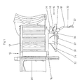
- a telescopic aircraft bridge (10), of which only the front part is shown in Fig. 1, comprises a head (12), on the underside (14) of which a device (16) for stowing a supply cable (18) of a central electrical system for aircraft is attached.
- the cable winding device (16) is moved horizontally or vertically together with the passenger boarding bridge (10) and fixed in the desired position.
- the supply cable is connected via a connection box (not shown) to a connecting cable piece (26) which extends along the telescopic passenger boarding bridge (10).
- the construction of the cable winding device (16) can correspond to that of the European patent application EP-A-01630250.
- the cable has a section (28) which is deflected into the axis of rotation of the drum (24) and which, in turn, extends into a section in the housing (24) of exposed spirals and when unwinding the connecting cable (18) while reducing radial Expansion is greater and when winding is carried out, the radial expansion is increased by weakening spirally twistable wires.
- the drum (24) receiving the connecting cable (18) is connected to the housing (30) or the underside (14) of the head (12) via struts (32).
- the cable winding device (16) can be rotated clockwise or counterclockwise via a geared motor (34), depending on whether the supply cable (18) wound on the drum (24) or to be removed from it.
- Support rollers (36) are provided to ensure that the supply cable (18), that is to say the section (20), is inserted gently into the drum (24) via the opening (40).
- rollers for reducing the friction can be arranged peripherally on the peripheral surface of the drum (24), as can be seen, for example, from PCT / EP 86/00142.
- the plug connector (22) hangs freely in the known cable winding devices, so it can exert an uncontrolled oscillating movement, with the risk that the wires of the supply cable break, which means that the supply cable must be replaced or at least shortened is.
- a holder (42) is now provided for a tubular element (44) through which the supply cable (18) can be pulled out of the cable winding device (16) or inserted into it.
- a tube-shaped centering element (46) is also assigned to the tube (44), which can also be referred to as a guide element, which emanates from the plug unit (22), which can be designed as a panel.
- This centering element (46) clearly surrounds the supply cable (18) inserted into the plug unit (22), ie the section (20).
- the diameter of the centering element (46) is smaller than the inside diameter of the guide element (44), so as - as shown in FIG. 3 - the centering element (46) up to a stop (48) in the guide element (44) when the supply cable is rolled up ( 18) to be able to bring.
- the supply cable (18) when it is not used, that is when it is largely wound on the cable winding device (16), it can no longer oscillate freely, so that the wires of the supply cable (18) are consequently also protected.
- the graphic representations further clarify that the holder (42) can be adjusted relative to the cable winding device (16) in order to be able to adjust the insertion angle of the centering element (46) into the guide element (44). This ensures that during the transition from the supply cable (18) to the centering element (46) there are no impact forces on the supply cable (18) in the region of the free end of the centering element (46).
- the insertion of the centering element (46) into the guide element (44) is further facilitated in that the opening (50) of the guide element (44) is expanded like a trumpet, at least on the inside.
- the front free end (52) of the centering element (46) can be chamfered.
- Both the centering element (46) and the guide element (44) can be detachably connected to the plug unit (42) or the holder (42) with screw connections.
- the holder (42) which can be in the form of a tubular or cuboid housing, is connected to the cable winding device (16) via flat irons extending from it, the connection itself being effected via elongated holes in order to adjust the angle of inclination of the holder (42) can.
- the guide element is thus divided into two sections, an inner section (54) and an outer section (56), which are spaced apart from one another and are connected to one another by a flexible element such as a tension spring (58) or the like.
- a flexible element such as a tension spring (58) or the like.
Applications Claiming Priority (4)
| Application Number | Priority Date | Filing Date | Title |
|---|---|---|---|
| DE8913225U | 1989-11-08 | ||
| DE8913225U DE8913225U1 (fr) | 1989-11-08 | 1989-11-08 | |
| DE8914558U | 1989-12-11 | ||
| DE8914558U DE8914558U1 (fr) | 1989-11-08 | 1989-12-11 |
Publications (3)
| Publication Number | Publication Date |
|---|---|
| EP0427041A2 true EP0427041A2 (fr) | 1991-05-15 |
| EP0427041A3 EP0427041A3 (en) | 1991-11-21 |
| EP0427041B1 EP0427041B1 (fr) | 1995-03-15 |
Family
ID=25955487
Family Applications (1)
| Application Number | Title | Priority Date | Filing Date |
|---|---|---|---|
| EP90120280A Expired - Lifetime EP0427041B1 (fr) | 1989-11-08 | 1990-10-23 | Dispositif d'enroulement de câble |
Country Status (6)
| Country | Link |
|---|---|
| US (1) | US5145040A (fr) |
| EP (1) | EP0427041B1 (fr) |
| AT (1) | ATE120051T1 (fr) |
| DE (1) | DE59008709D1 (fr) |
| DK (1) | DK0427041T3 (fr) |
| ES (1) | ES2071722T3 (fr) |
Cited By (1)
| Publication number | Priority date | Publication date | Assignee | Title |
|---|---|---|---|---|
| CN103249599A (zh) * | 2010-11-24 | 2013-08-14 | 戴姆勒股份公司 | 用于运行设置在可运动的透明面元件中和/或上的电负载的装置 |
Families Citing this family (4)
| Publication number | Priority date | Publication date | Assignee | Title |
|---|---|---|---|---|
| JP3347433B2 (ja) * | 1993-10-19 | 2002-11-20 | 本田技研工業株式会社 | 電動車両の充電コード収納構造 |
| US5810135A (en) * | 1996-09-25 | 1998-09-22 | General Cable Industries, Inc. | Plug and switch assembly |
| WO2008059757A1 (fr) * | 2006-11-14 | 2008-05-22 | Panasonic Corporation | Capteur |
| FI11095U1 (fi) * | 2015-08-12 | 2016-01-12 | Mattoasennus Karjalainen Oy | Automaattisesti kelautuva lämmitysjohtojärjestely ajoneuvoon |
Citations (5)
| Publication number | Priority date | Publication date | Assignee | Title |
|---|---|---|---|---|
| US1725308A (en) * | 1924-09-03 | 1929-08-20 | Shoenberg | Combined cord reel |
| CH419273A (de) * | 1963-09-12 | 1966-08-31 | Bommeli Paul | Elektrische Stecker-Anordnung in Mauerwänden |
| EP0008352A1 (fr) * | 1978-07-12 | 1980-03-05 | Western Gear Corporation | Système d'enroulement pour conduits flexibles et câbles |
| EP0163025A2 (fr) * | 1984-05-30 | 1985-12-04 | Manfred Fladung GmbH | Dispositif d'emmagasinage pour un câble de connexion d'une installation centrale d'alimentation de réseau de bord |
| DE8914558U1 (fr) * | 1989-11-08 | 1990-05-31 | Manfred Fladung Gmbh, 8752 Moembris, De |
Family Cites Families (11)
| Publication number | Priority date | Publication date | Assignee | Title |
|---|---|---|---|---|
| US2013733A (en) * | 1934-11-06 | 1935-09-10 | Claude M Murphy | Winding reel for cables |
| US2543176A (en) * | 1948-03-20 | 1951-02-27 | Aero Motive Mfg Company | Reel |
| US3840713A (en) * | 1972-05-08 | 1974-10-08 | Mc Graw Edison Co | Portable reel for flexible conductors |
| US4138177A (en) * | 1976-04-16 | 1979-02-06 | Valer Andrew F Van | Safety vehicle power distribution system |
| DE3209294A1 (de) * | 1982-03-13 | 1983-09-22 | M.A.N. Maschinenfabrik Augsburg-Nürnberg AG, 4200 Oberhausen | Gleisloses untertagefahrzeug |
| DE3304276C1 (de) * | 1983-02-08 | 1984-08-02 | Schabmüller, Heinz, 8132 Tutzing | Verstauvorrichtung fuer das Anschlusskabel einer zentralen Bordnetzversorgungsanlage auf Flughaefen |
| US4825986A (en) * | 1983-09-02 | 1989-05-02 | Wyle Laboratories | Remotely controllable cable assembly |
| WO1986005632A1 (fr) * | 1985-03-15 | 1986-09-25 | Manfred Fladung Gmbh | Dispositif de stockage du cable d'alimentation de preference d'un reseau d'alimentation de bord dans des aeroports |
| US4842108A (en) * | 1985-05-28 | 1989-06-27 | Circle A Product, Inc. | Power retract electric cord reel |
| US4653833A (en) * | 1985-06-27 | 1987-03-31 | Czubernat Donald A | Retractable booster cable device |
| US5034571A (en) * | 1989-11-13 | 1991-07-23 | Galloway Albert D | Power cord retractor for recreational vehicle |
-
1990
- 1990-10-23 DK DK90120280.4T patent/DK0427041T3/da active
- 1990-10-23 AT AT90120280T patent/ATE120051T1/de not_active IP Right Cessation
- 1990-10-23 EP EP90120280A patent/EP0427041B1/fr not_active Expired - Lifetime
- 1990-10-23 DE DE59008709T patent/DE59008709D1/de not_active Expired - Fee Related
- 1990-10-23 ES ES90120280T patent/ES2071722T3/es not_active Expired - Lifetime
- 1990-10-31 US US07/606,115 patent/US5145040A/en not_active Expired - Lifetime
Patent Citations (5)
| Publication number | Priority date | Publication date | Assignee | Title |
|---|---|---|---|---|
| US1725308A (en) * | 1924-09-03 | 1929-08-20 | Shoenberg | Combined cord reel |
| CH419273A (de) * | 1963-09-12 | 1966-08-31 | Bommeli Paul | Elektrische Stecker-Anordnung in Mauerwänden |
| EP0008352A1 (fr) * | 1978-07-12 | 1980-03-05 | Western Gear Corporation | Système d'enroulement pour conduits flexibles et câbles |
| EP0163025A2 (fr) * | 1984-05-30 | 1985-12-04 | Manfred Fladung GmbH | Dispositif d'emmagasinage pour un câble de connexion d'une installation centrale d'alimentation de réseau de bord |
| DE8914558U1 (fr) * | 1989-11-08 | 1990-05-31 | Manfred Fladung Gmbh, 8752 Moembris, De |
Cited By (1)
| Publication number | Priority date | Publication date | Assignee | Title |
|---|---|---|---|---|
| CN103249599A (zh) * | 2010-11-24 | 2013-08-14 | 戴姆勒股份公司 | 用于运行设置在可运动的透明面元件中和/或上的电负载的装置 |
Also Published As
| Publication number | Publication date |
|---|---|
| US5145040A (en) | 1992-09-08 |
| EP0427041A3 (en) | 1991-11-21 |
| EP0427041B1 (fr) | 1995-03-15 |
| DK0427041T3 (da) | 1995-07-10 |
| DE59008709D1 (de) | 1995-04-20 |
| ES2071722T3 (es) | 1995-07-01 |
| ATE120051T1 (de) | 1995-04-15 |
Similar Documents
| Publication | Publication Date | Title |
|---|---|---|
| DE69318291T3 (de) | Verfahren und einrichtung zur herstellung eines verbindungskabels | |
| DE1051770B (de) | Kontinuierlich arbeitende Abwickeleinrichtung fuer Draht | |
| EP0427041B1 (fr) | Dispositif d'enroulement de câble | |
| EP0163025B1 (fr) | Dispositif d'emmagasinage pour un câble de connexion d'une installation centrale d'alimentation de réseau de bord | |
| WO1992001323A1 (fr) | Dispositif servant a abriter un cable epais | |
| EP0445312B1 (fr) | Dispositif de pose de câbles ou de tuyaux flexibles sur un trajet de pose | |
| DE3610635A1 (de) | Verbesserte markise in form eines dachs | |
| DE1589238B2 (de) | Verfahren und vorrichtung zum wickeln eines gluehkoerpers fuer eine elektrische lampe | |
| DE3317920A1 (de) | Vorrichtung zum anbringen einer versetzbaren halterung an einer rohrwand eines dampferzeugers | |
| EP0049734B1 (fr) | Dispositif pour le contrôle du déroulement du raccord flexible reliant un appareil à un satellite soumis à un mouvement giratoire | |
| DE10008613C2 (de) | Übergangsstück | |
| DE8419599U1 (de) | Kabelaufrollvorrichtung für Anschlußkabel von Bordnetzversorgungsanlagen für Flugzeuge | |
| DE3017195C2 (fr) | ||
| DE3427788C1 (de) | Vorrichtung zum nachträglichen Einziehen von Kabeln in Kabelschutzrohre | |
| EP0437709B1 (fr) | Elément allongé pour tirage dans un conduit et procédé d'utilisation | |
| EP0252914B1 (fr) | Dispositif de stockage du cable d'alimentation de preference d'un reseau d'alimentation de bord dans des aeroports | |
| EP3633260A1 (fr) | Unité d'avance pour un système d'inspection de caméra | |
| DE3038704C2 (fr) | ||
| DE627171C (de) | Verbindungsmuffe fuer unter Zugspannung stehende elektrische Luftkabel | |
| DE3901063A1 (de) | Verfahren zum einziehen eines kabels in ein kabelkanalsystem und vorrichtung zum aufwickeln eines kabels | |
| EP0238436B1 (fr) | Entraînement pour un chariot de boucles | |
| DE2618465C2 (de) | Führungs- und Spanneinrichtung für Leitungen im Fahrzeugrahmen | |
| EP1117589B1 (fr) | Passerelle telescopique a ligne d'alimentation et logement prevu pour ladite ligne d'alimentation | |
| WO1991000537A1 (fr) | Procede et dispositif pour passer des cables en fibres optiques dans des tubes protecteurs | |
| DE4239916C1 (de) | Vorrichtung zur Prüfung von Hohlräumen |
Legal Events
| Date | Code | Title | Description |
|---|---|---|---|
| PUAI | Public reference made under article 153(3) epc to a published international application that has entered the european phase |
Free format text: ORIGINAL CODE: 0009012 |
|
| AK | Designated contracting states |
Kind code of ref document: A2 Designated state(s): AT BE CH DE DK ES FR GB GR IT LI LU NL SE |
|
| PUAL | Search report despatched |
Free format text: ORIGINAL CODE: 0009013 |
|
| AK | Designated contracting states |
Kind code of ref document: A3 Designated state(s): AT BE CH DE DK ES FR GB GR IT LI LU NL SE |
|
| 17P | Request for examination filed |
Effective date: 19911108 |
|
| 17Q | First examination report despatched |
Effective date: 19931210 |
|
| GRAA | (expected) grant |
Free format text: ORIGINAL CODE: 0009210 |
|
| AK | Designated contracting states |
Kind code of ref document: B1 Designated state(s): AT BE CH DE DK ES FR GB GR IT LI LU NL SE |
|
| PG25 | Lapsed in a contracting state [announced via postgrant information from national office to epo] |
Ref country code: GR Free format text: LAPSE BECAUSE OF FAILURE TO SUBMIT A TRANSLATION OF THE DESCRIPTION OR TO PAY THE FEE WITHIN THE PRESCRIBED TIME-LIMIT Effective date: 19950315 Ref country code: BE Effective date: 19950315 |
|
| REF | Corresponds to: |
Ref document number: 120051 Country of ref document: AT Date of ref document: 19950415 Kind code of ref document: T |
|
| REF | Corresponds to: |
Ref document number: 59008709 Country of ref document: DE Date of ref document: 19950420 |
|
| ITF | It: translation for a ep patent filed |
Owner name: JACOBACCI & PERANI S.P.A. |
|
| ET | Fr: translation filed | ||
| REG | Reference to a national code |
Ref country code: ES Ref legal event code: FG2A Ref document number: 2071722 Country of ref document: ES Kind code of ref document: T3 |
|
| REG | Reference to a national code |
Ref country code: DK Ref legal event code: T3 |
|
| GBT | Gb: translation of ep patent filed (gb section 77(6)(a)/1977) |
Effective date: 19950612 |
|
| PG25 | Lapsed in a contracting state [announced via postgrant information from national office to epo] |
Ref country code: LU Free format text: LAPSE BECAUSE OF NON-PAYMENT OF DUE FEES Effective date: 19951031 |
|
| PLBE | No opposition filed within time limit |
Free format text: ORIGINAL CODE: 0009261 |
|
| STAA | Information on the status of an ep patent application or granted ep patent |
Free format text: STATUS: NO OPPOSITION FILED WITHIN TIME LIMIT |
|
| 26N | No opposition filed | ||
| PGFP | Annual fee paid to national office [announced via postgrant information from national office to epo] |
Ref country code: DK Payment date: 19980916 Year of fee payment: 9 |
|
| PGFP | Annual fee paid to national office [announced via postgrant information from national office to epo] |
Ref country code: SE Payment date: 19980928 Year of fee payment: 9 |
|
| PGFP | Annual fee paid to national office [announced via postgrant information from national office to epo] |
Ref country code: ES Payment date: 19981013 Year of fee payment: 9 |
|
| PGFP | Annual fee paid to national office [announced via postgrant information from national office to epo] |
Ref country code: GB Payment date: 19981023 Year of fee payment: 9 |
|
| PGFP | Annual fee paid to national office [announced via postgrant information from national office to epo] |
Ref country code: DE Payment date: 19981028 Year of fee payment: 9 Ref country code: AT Payment date: 19981028 Year of fee payment: 9 |
|
| PGFP | Annual fee paid to national office [announced via postgrant information from national office to epo] |
Ref country code: FR Payment date: 19981030 Year of fee payment: 9 |
|
| PGFP | Annual fee paid to national office [announced via postgrant information from national office to epo] |
Ref country code: NL Payment date: 19981031 Year of fee payment: 9 |
|
| PGFP | Annual fee paid to national office [announced via postgrant information from national office to epo] |
Ref country code: CH Payment date: 19981105 Year of fee payment: 9 |
|
| PG25 | Lapsed in a contracting state [announced via postgrant information from national office to epo] |
Ref country code: GB Free format text: LAPSE BECAUSE OF NON-PAYMENT OF DUE FEES Effective date: 19991023 Ref country code: DK Free format text: LAPSE BECAUSE OF NON-PAYMENT OF DUE FEES Effective date: 19991023 Ref country code: AT Free format text: LAPSE BECAUSE OF NON-PAYMENT OF DUE FEES Effective date: 19991023 |
|
| PG25 | Lapsed in a contracting state [announced via postgrant information from national office to epo] |
Ref country code: ES Free format text: LAPSE BECAUSE OF NON-PAYMENT OF DUE FEES Effective date: 19991024 |
|
| PG25 | Lapsed in a contracting state [announced via postgrant information from national office to epo] |
Ref country code: SE Free format text: THE PATENT HAS BEEN ANNULLED BY A DECISION OF A NATIONAL AUTHORITY Effective date: 19991030 |
|
| PG25 | Lapsed in a contracting state [announced via postgrant information from national office to epo] |
Ref country code: LI Free format text: LAPSE BECAUSE OF NON-PAYMENT OF DUE FEES Effective date: 19991031 Ref country code: CH Free format text: LAPSE BECAUSE OF NON-PAYMENT OF DUE FEES Effective date: 19991031 |
|
| PG25 | Lapsed in a contracting state [announced via postgrant information from national office to epo] |
Ref country code: NL Free format text: LAPSE BECAUSE OF NON-PAYMENT OF DUE FEES Effective date: 20000501 |
|
| GBPC | Gb: european patent ceased through non-payment of renewal fee |
Effective date: 19991023 |
|
| REG | Reference to a national code |
Ref country code: CH Ref legal event code: PL |
|
| EUG | Se: european patent has lapsed |
Ref document number: 90120280.4 |
|
| PG25 | Lapsed in a contracting state [announced via postgrant information from national office to epo] |
Ref country code: FR Free format text: LAPSE BECAUSE OF NON-PAYMENT OF DUE FEES Effective date: 20000630 |
|
| NLV4 | Nl: lapsed or anulled due to non-payment of the annual fee |
Effective date: 20000501 |
|
| REG | Reference to a national code |
Ref country code: DK Ref legal event code: EBP |
|
| PG25 | Lapsed in a contracting state [announced via postgrant information from national office to epo] |
Ref country code: DE Free format text: LAPSE BECAUSE OF NON-PAYMENT OF DUE FEES Effective date: 20000801 |
|
| REG | Reference to a national code |
Ref country code: FR Ref legal event code: ST |
|
| REG | Reference to a national code |
Ref country code: ES Ref legal event code: FD2A Effective date: 20001113 |
|
| PG25 | Lapsed in a contracting state [announced via postgrant information from national office to epo] |
Ref country code: IT Free format text: LAPSE BECAUSE OF NON-PAYMENT OF DUE FEES;WARNING: LAPSES OF ITALIAN PATENTS WITH EFFECTIVE DATE BEFORE 2007 MAY HAVE OCCURRED AT ANY TIME BEFORE 2007. THE CORRECT EFFECTIVE DATE MAY BE DIFFERENT FROM THE ONE RECORDED. Effective date: 20051023 |