EP0425656B1 - Vorrichtung zum formen von endlosschleifen aus einer folie - Google Patents
Vorrichtung zum formen von endlosschleifen aus einer folie Download PDFInfo
- Publication number
- EP0425656B1 EP0425656B1 EP90908905A EP90908905A EP0425656B1 EP 0425656 B1 EP0425656 B1 EP 0425656B1 EP 90908905 A EP90908905 A EP 90908905A EP 90908905 A EP90908905 A EP 90908905A EP 0425656 B1 EP0425656 B1 EP 0425656B1
- Authority
- EP
- European Patent Office
- Prior art keywords
- drum
- sheet
- portions
- perforations
- relative
- Prior art date
- Legal status (The legal status is an assumption and is not a legal conclusion. Google has not performed a legal analysis and makes no representation as to the accuracy of the status listed.)
- Expired - Lifetime
Links
- 239000000463 material Substances 0.000 title claims abstract description 19
- 238000003466 welding Methods 0.000 claims description 18
- 241001125879 Gobio Species 0.000 description 8
- 230000013011 mating Effects 0.000 description 2
- 230000003287 optical effect Effects 0.000 description 2
- 239000013307 optical fiber Substances 0.000 description 2
- 238000007789 sealing Methods 0.000 description 2
- 230000037303 wrinkles Effects 0.000 description 2
- 238000010276 construction Methods 0.000 description 1
- 238000005553 drilling Methods 0.000 description 1
- 230000000694 effects Effects 0.000 description 1
- 239000000839 emulsion Substances 0.000 description 1
- 238000009434 installation Methods 0.000 description 1
- 238000012423 maintenance Methods 0.000 description 1
- 238000005259 measurement Methods 0.000 description 1
- 238000000926 separation method Methods 0.000 description 1
- 125000006850 spacer group Chemical group 0.000 description 1
Images


Classifications
-
- B—PERFORMING OPERATIONS; TRANSPORTING
- B29—WORKING OF PLASTICS; WORKING OF SUBSTANCES IN A PLASTIC STATE IN GENERAL
- B29C—SHAPING OR JOINING OF PLASTICS; SHAPING OF MATERIAL IN A PLASTIC STATE, NOT OTHERWISE PROVIDED FOR; AFTER-TREATMENT OF THE SHAPED PRODUCTS, e.g. REPAIRING
- B29C66/00—General aspects of processes or apparatus for joining preformed parts
- B29C66/80—General aspects of machine operations or constructions and parts thereof
- B29C66/83—General aspects of machine operations or constructions and parts thereof characterised by the movement of the joining or pressing tools
- B29C66/836—Moving relative to and tangentially to the parts to be joined, e.g. transversely to the displacement of the parts to be joined, e.g. using a X-Y table
-
- B—PERFORMING OPERATIONS; TRANSPORTING
- B29—WORKING OF PLASTICS; WORKING OF SUBSTANCES IN A PLASTIC STATE IN GENERAL
- B29C—SHAPING OR JOINING OF PLASTICS; SHAPING OF MATERIAL IN A PLASTIC STATE, NOT OTHERWISE PROVIDED FOR; AFTER-TREATMENT OF THE SHAPED PRODUCTS, e.g. REPAIRING
- B29C53/00—Shaping by bending, folding, twisting, straightening or flattening; Apparatus therefor
- B29C53/36—Bending and joining, e.g. for making hollow articles
- B29C53/38—Bending and joining, e.g. for making hollow articles by bending sheets or strips at right angles to the longitudinal axis of the article being formed and joining the edges
- B29C53/40—Bending and joining, e.g. for making hollow articles by bending sheets or strips at right angles to the longitudinal axis of the article being formed and joining the edges for articles of definite length, i.e. discrete articles
-
- B—PERFORMING OPERATIONS; TRANSPORTING
- B29—WORKING OF PLASTICS; WORKING OF SUBSTANCES IN A PLASTIC STATE IN GENERAL
- B29C—SHAPING OR JOINING OF PLASTICS; SHAPING OF MATERIAL IN A PLASTIC STATE, NOT OTHERWISE PROVIDED FOR; AFTER-TREATMENT OF THE SHAPED PRODUCTS, e.g. REPAIRING
- B29C65/00—Joining or sealing of preformed parts, e.g. welding of plastics materials; Apparatus therefor
- B29C65/02—Joining or sealing of preformed parts, e.g. welding of plastics materials; Apparatus therefor by heating, with or without pressure
- B29C65/08—Joining or sealing of preformed parts, e.g. welding of plastics materials; Apparatus therefor by heating, with or without pressure using ultrasonic vibrations
-
- B—PERFORMING OPERATIONS; TRANSPORTING
- B29—WORKING OF PLASTICS; WORKING OF SUBSTANCES IN A PLASTIC STATE IN GENERAL
- B29C—SHAPING OR JOINING OF PLASTICS; SHAPING OF MATERIAL IN A PLASTIC STATE, NOT OTHERWISE PROVIDED FOR; AFTER-TREATMENT OF THE SHAPED PRODUCTS, e.g. REPAIRING
- B29C65/00—Joining or sealing of preformed parts, e.g. welding of plastics materials; Apparatus therefor
- B29C65/78—Means for handling the parts to be joined, e.g. for making containers or hollow articles, e.g. means for handling sheets, plates, web-like materials, tubular articles, hollow articles or elements to be joined therewith; Means for discharging the joined articles from the joining apparatus
- B29C65/7802—Positioning the parts to be joined, e.g. aligning, indexing or centring
- B29C65/7832—Positioning the parts to be joined, e.g. aligning, indexing or centring by setting the overlap between the parts to be joined, e.g. the overlap between sheets, plates or web-like materials
-
- B—PERFORMING OPERATIONS; TRANSPORTING
- B29—WORKING OF PLASTICS; WORKING OF SUBSTANCES IN A PLASTIC STATE IN GENERAL
- B29C—SHAPING OR JOINING OF PLASTICS; SHAPING OF MATERIAL IN A PLASTIC STATE, NOT OTHERWISE PROVIDED FOR; AFTER-TREATMENT OF THE SHAPED PRODUCTS, e.g. REPAIRING
- B29C65/00—Joining or sealing of preformed parts, e.g. welding of plastics materials; Apparatus therefor
- B29C65/78—Means for handling the parts to be joined, e.g. for making containers or hollow articles, e.g. means for handling sheets, plates, web-like materials, tubular articles, hollow articles or elements to be joined therewith; Means for discharging the joined articles from the joining apparatus
- B29C65/7841—Holding or clamping means for handling purposes
- B29C65/7847—Holding or clamping means for handling purposes using vacuum to hold at least one of the parts to be joined
-
- B—PERFORMING OPERATIONS; TRANSPORTING
- B29—WORKING OF PLASTICS; WORKING OF SUBSTANCES IN A PLASTIC STATE IN GENERAL
- B29C—SHAPING OR JOINING OF PLASTICS; SHAPING OF MATERIAL IN A PLASTIC STATE, NOT OTHERWISE PROVIDED FOR; AFTER-TREATMENT OF THE SHAPED PRODUCTS, e.g. REPAIRING
- B29C66/00—General aspects of processes or apparatus for joining preformed parts
- B29C66/01—General aspects dealing with the joint area or with the area to be joined
- B29C66/05—Particular design of joint configurations
- B29C66/10—Particular design of joint configurations particular design of the joint cross-sections
- B29C66/11—Joint cross-sections comprising a single joint-segment, i.e. one of the parts to be joined comprising a single joint-segment in the joint cross-section
- B29C66/112—Single lapped joints
- B29C66/1122—Single lap to lap joints, i.e. overlap joints
-
- B—PERFORMING OPERATIONS; TRANSPORTING
- B29—WORKING OF PLASTICS; WORKING OF SUBSTANCES IN A PLASTIC STATE IN GENERAL
- B29C—SHAPING OR JOINING OF PLASTICS; SHAPING OF MATERIAL IN A PLASTIC STATE, NOT OTHERWISE PROVIDED FOR; AFTER-TREATMENT OF THE SHAPED PRODUCTS, e.g. REPAIRING
- B29C66/00—General aspects of processes or apparatus for joining preformed parts
- B29C66/40—General aspects of joining substantially flat articles, e.g. plates, sheets or web-like materials; Making flat seams in tubular or hollow articles; Joining single elements to substantially flat surfaces
- B29C66/41—Joining substantially flat articles ; Making flat seams in tubular or hollow articles
- B29C66/43—Joining a relatively small portion of the surface of said articles
- B29C66/432—Joining a relatively small portion of the surface of said articles for making tubular articles or closed loops, e.g. by joining several sheets ; for making hollow articles or hollow preforms
- B29C66/4322—Joining a relatively small portion of the surface of said articles for making tubular articles or closed loops, e.g. by joining several sheets ; for making hollow articles or hollow preforms by joining a single sheet to itself
-
- B—PERFORMING OPERATIONS; TRANSPORTING
- B29—WORKING OF PLASTICS; WORKING OF SUBSTANCES IN A PLASTIC STATE IN GENERAL
- B29C—SHAPING OR JOINING OF PLASTICS; SHAPING OF MATERIAL IN A PLASTIC STATE, NOT OTHERWISE PROVIDED FOR; AFTER-TREATMENT OF THE SHAPED PRODUCTS, e.g. REPAIRING
- B29C66/00—General aspects of processes or apparatus for joining preformed parts
- B29C66/40—General aspects of joining substantially flat articles, e.g. plates, sheets or web-like materials; Making flat seams in tubular or hollow articles; Joining single elements to substantially flat surfaces
- B29C66/41—Joining substantially flat articles ; Making flat seams in tubular or hollow articles
- B29C66/43—Joining a relatively small portion of the surface of said articles
- B29C66/432—Joining a relatively small portion of the surface of said articles for making tubular articles or closed loops, e.g. by joining several sheets ; for making hollow articles or hollow preforms
- B29C66/4324—Joining a relatively small portion of the surface of said articles for making tubular articles or closed loops, e.g. by joining several sheets ; for making hollow articles or hollow preforms for making closed loops, e.g. belts
-
- B—PERFORMING OPERATIONS; TRANSPORTING
- B29—WORKING OF PLASTICS; WORKING OF SUBSTANCES IN A PLASTIC STATE IN GENERAL
- B29C—SHAPING OR JOINING OF PLASTICS; SHAPING OF MATERIAL IN A PLASTIC STATE, NOT OTHERWISE PROVIDED FOR; AFTER-TREATMENT OF THE SHAPED PRODUCTS, e.g. REPAIRING
- B29C66/00—General aspects of processes or apparatus for joining preformed parts
- B29C66/40—General aspects of joining substantially flat articles, e.g. plates, sheets or web-like materials; Making flat seams in tubular or hollow articles; Joining single elements to substantially flat surfaces
- B29C66/49—Internally supporting the, e.g. tubular, article during joining
-
- B—PERFORMING OPERATIONS; TRANSPORTING
- B29—WORKING OF PLASTICS; WORKING OF SUBSTANCES IN A PLASTIC STATE IN GENERAL
- B29C—SHAPING OR JOINING OF PLASTICS; SHAPING OF MATERIAL IN A PLASTIC STATE, NOT OTHERWISE PROVIDED FOR; AFTER-TREATMENT OF THE SHAPED PRODUCTS, e.g. REPAIRING
- B29C66/00—General aspects of processes or apparatus for joining preformed parts
- B29C66/80—General aspects of machine operations or constructions and parts thereof
- B29C66/83—General aspects of machine operations or constructions and parts thereof characterised by the movement of the joining or pressing tools
- B29C66/832—Reciprocating joining or pressing tools
- B29C66/8322—Joining or pressing tools reciprocating along one axis
-
- B—PERFORMING OPERATIONS; TRANSPORTING
- B29—WORKING OF PLASTICS; WORKING OF SUBSTANCES IN A PLASTIC STATE IN GENERAL
- B29L—INDEXING SCHEME ASSOCIATED WITH SUBCLASS B29C, RELATING TO PARTICULAR ARTICLES
- B29L2031/00—Other particular articles
- B29L2031/764—Photographic equipment or accessories
- B29L2031/7644—Films
Definitions
- the present invention relates to apparatus for splicing together the ends of a sheet of material to form an endless loop and, more specifically, to such an apparatus which produces a cylindrical loop and accurately locates perforations or other features along an edge of the sheet in the area where the ends of the sheet are spliced together.
- Document GB-A-2,188,280, published September 30, 1987 discloses an apparatus for fabricating endless photoconductor belts from a web stock.
- the apparatus comprises a wrap station, a weld station and a discharge station.
- the web stock in sheet form initially is wrapped around a first mandrel located at the wrap station and held in place on the mandrel by suction applied from inside the mandrel.
- the web is severed at a point which enables the trailing end of the web to overlap the leading end, thus forming a complete turn on the mandrel.
- the first mandrel is conveyed to the weld station while a second mandrel is moved to the wrap station.
- the overlapping ends of the web stock are welded together ultrasonically to form an endless loop of photoconductor belt. Then the belt and mandrel are advanced to the discharge station where the belt is removed from the apparatus.
- the belt fabricating apparatus is somewhat complicated due to the need for transporting mandrels between the various stations, and there apparently is no provision for providing exact positioning of features, such as perforations, that are commonly found on photoconductors.
- the present invention relates to apparatus according to claims 1 and 5.
- a preferred embodiment of the apparatus of the present invention is generally designated 20 and comprises a frame 22 for supporting the various portions of the apparatus.
- a drum generally designated 24 is supported by frame 22 and projects from one side thereof.
- an elongate sheet 26 of material such as a sheet of photoconductor material, can be positioned around drum 24 and the ends thereof bonded together to form an endless loop.
- Sheet 26 may have a plurality of equally spaced perforations 28 or other similar features along an edge portion thereof. When such features are present, the ends of the sheet are overlapped and then adjusted with respect to each other to maintain continuity of the pitch between the perforations or other features on the sheet in the area of the overlap.
- the relationship between the perforations is detected by a vision camera system generally designated 30 which can be positioned directly above the overlap area.
- the vision camera system acquires a video image of the relationship of the perforation, and then the resulting video signal is input to a computer vision processor of the system where a subpixel measurement is performed on the edge of the perforation.
- the processor produces an output signal indicative of the relationship between perforations in the area of the overlap. As explained later, this output signal is used to control adjustment of the drum until the desired relationship is obtained between perforations in the area of the overlap.
- a commercially available vision camera system with a resolution of 512 pixels by 512 pixels is suitable for use with the splicing apparatus.
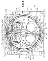
- Drum 24 will now be described in more detail with particular reference to Figs. 3, 4 and 6 of the drawings.
- Drum 24 is preferably made in two substantially semi-cylindrical portions 24a, 24b which are positioned closely adjacent to each other, but slightly spaced from each other.
- the drum portions 24a, and 24b as illustrated in Fig. 3 are aligned along a plane that is offset in a clockwise direction a few degrees from a vertical plane through the drawing.
- a hinge or flexure joint 34 is connected to both drum portions 24a, 24b along the lower edge thereof as shown in Fig. 3. Hinge 34 enables the drum portions to move relative to each other about the hinge 34 so that one of the axially extending edges of the drum portions at the top of the drawing can be moved toward and away from the other portion as described in detail later.
- Drum portion 24a comprises a generally semi-cylindrical outer wall 40 that is undercut as shown at 41 at its radially inner edge and at the end adjacent frame 22.
- a plurality of semi-circular gudgeons 42 are secured to the inner surface of wall 40 and extend to the right edge of the drum portion 24a.
- a pair of circular openings 44 are provided in gudgeons 42 to permit access to the interior of the drum for assembly, adjustments etc.
- Rectangular plates 46, 48 are secured to the outer edges of wall 40 and the gudgeons at the top and bottom edges thereof. Gudgeons 42 and plates 46, 48, when secured to the wall 40 and each other as described, provide a rigid generally semi-cylindrical drum portion that has good structural integrity.
- a drum flange 50 of generally semi-circular configuration is secured to one end of wall 40 by bolts 52.
- Flange 50 is located at the end of the drum adjacent the frame 22, and the inner edge of flange 50 is coextensive with the outer edge of the undercut area 41.
- a plurality of locating pads 54 are bolted to flange 50 in the area radially outside the wall 40. Pads 54 establish the position of the left side edge of the sheet 26 of material on the drum.
- a face plate 60 is bolted to the frame 22.
- a semi-circular drum locating segment 62 is bolted to the face plate.
- the radially outer edge of the segment 62 is the same diameter as the radially inner edge of the undercut area 41 of wall 40 of the drum portion 24a.
- the drum portion 24a is positioned against the face plate 60 with drum flange 50 abutting the face plate 60 and with the radially inner edge of the undercut area 41 of wall 40 positioned along the outer edge of the segment 62.
- drum portion 24a is bolted to the face plate 60 with a plurality of screws 64. This firmly and rigidly fixes the left portion 24a of the drum to the face plate 60 and thus supports it from the frame 22.
- the face plate 60 has a plurality of circular openings 66 which are generally aligned with the openings 44 in gudgeons 42 and in the similar openings described later in drum portion 24b. These overlapping openings permit access to the interior of the drum for installation or maintenance of the apparatus.
- Portion 24b of the drum is substantially the mirror image of the drum portion 24a. More specifically, drum portion 24b has a semi-cylindrical wall 70 and a plurality of gudgeons 72 that are welded or otherwise secured to the inner surface of wall 70. Gudgeons 72 have openings 74 that generally overlap the openings 66 in the face plate 60. Rectangular plates 76, 78 are secured to the outer edges of the upper and lower edges of the gudgeons. Plates 76, 78 are in close facing relationship to the corresponding plates 46, 48 of the drum portion 24a.
- a drum flange 80 is secured to the edge of wall 70 nearest the face plate 60 by a plurality of bolts 82.
- Locating pads 84 are provided on the drum flange 80 radially outwardly of the wall 70. These locating pads together with pads 54 serve to establish the position of the sheet 26 on the drum.
- drum portion 24a is bolted directly to the face plate 60 as explained hereinbefore, drum portion 24b is moveable relative to portion 24a about the hinge or flexure 34.
- a locating segment as shown at 62 is not required for the drum portion 24b.
- the edge of the drum portion 24b nearest to the face plate 60 needs to be spaced from plate 60 so the drum portion can move relative to that plate. This spacing can be assured by mating the drum flange 50 for portion 24a somewhat thicker than the drum flange 80 for the drum portion 24b.
- a spacer or shim can be provided between drum flange 50 and face plate 60 to separate the drum flanges from the face plate 60 by a distance sufficient to enable the drum portion 24b to move about the hinge 34.
- Drum portion 24b is pivoted about hinge 34 and relative to portion 24a by a power driven differential screw assembly generally designated 90.
- the differential screw assembly comprises a shaft 92 having its left end threaded into one end of a clevis 94, and the right end of the shaft is threaded into one end of a second clevis 96.
- a pulley 98 is fixed to the shaft 92 and a belt 100 is trained around the pulley and driven from a motor (not shown) so that the shaft 92 can be rotated in two opposite directions.
- Clevis 94 has a bifurcated end portion 94a with an opening 94b which receives the shank of a pin 102.
- the pin has an enlarged head 102a that engages one side of clevis 94, and a hitch pin 104 passes through the other end of pin 102. Head 102a and the hitch pin 104 hold the pin 102 against inadvertent movement relative to the clevis.
- pin 102 also passes through a clevis support plate 106 that is secured to the inner surface of the cylindrical wall 40 of the drum and fits between inside the bifurcated end 94b of the clevis. In this manner the clevis 94 is pivotally attached to the drum portion 24a.
- clevis 96 has a bifurcated end portion 96a with an opening 96b which receives a pin 108.
- a hitch pin 110 passes through the pin 108.
- the pin 108 also extends through a support plate 112 which is secured to the inner surface of cylindrical wall 70 of drum portion 24b.
- clevis 96 is pivotally attached to the drum portion 24b.
- the threads on the left end of shaft 92 and the right end clevis 94 are the same hand threads as on the right end of shaft 92 and the left end of clevis of 96.
- both are right-hand threads.
- the pitch of the threads on the left end of the shaft and clevis 94 differ from the pitch of the threads on the right end of the shaft and the of clevis 96.
- this arrangement enables vary small relative movement of the upper edge of drum portion 24b relative to drum portion 24a in response to rotation of the shaft.
- the threads on the shaft and clevises can be selected so that one complete revolution of the shaft will unscrew the shaft from the left clevis by 0.1 inch while simultaneously the right end of the shaft will be screwed into clevis 96 by 0.125 inch, thus resulting in a net movement of the upper edge of drum portion 24b toward drum portion 24a.
- the distance the upper edge of drum portion 24b moves is a function not only of the relationship of the threads as discussed above, but also of the relationship of the distance from the hinge axis to the pin 108 of the differential screw assembly and the distance from the hinge axis to the upper edge of drum portion 24a.
- the ability to achieve slight but controlled adjustment of drum portion 24b relative to portion 24a enables precise positioning of the overlapping portions of the ends of sheets 26, as explained later during the description of Figs. 10-12.
- Sensing apparatus 118 detects the movement of the shaft 92 and thus the position of drum portion 24b relative to the drum portion 24a.
- Sensing apparatus 118 comprises a sensor mounting plate 120 which is attached by bolts 122 to clevis 194. A portion of the plate 120 is cantilevered over the top of shaft 92 and has an arcuate recess 124 in the lower surface thereof.
- Three annular shaft collars 126, 128 and 130 are secured to shaft 92 for rotation and axial movement with the shaft.
- the outer diameters of the collars are such that they can fit within and are spaced from the recess 124 in the mounting plate 120.
- Collar 126 is used for determining the "home" position of the shaft 92.
- Collar 128 determines the maximum closed position of drum portion 24b relative to portion 24a, and collar 130 determines the maximum open position of the drum portion 24b relative to portion 24a.
- the sensing device 134 comprises a light emitter 136 that is connected to the left side of the mounting plate 120, and a light receiver 138 that is connected to the right side of the mounting plate.
- the light emitter may comprise a bundle of optical fibers that provide light from a remote source (not shown) to the mounting plate.
- the receiver 138 can comprise a bundle of optical fibers which receive light from the emitter 136 and transmits the light to a transducer (not shown) which signals the presence or absence of light in receiver 138.
- the emitter 136 and receiver 138 are connected to the mounting plate so that light from the emitter can travel through a passageway 140 in the plate and then pass through the arcuate recess 124 in the plate to enter another passageway 142 in the plate for delivery to the light receiver 138.
- Sensing device 132 is the same as device 134 and is spaced a short distance from device 134.
- the passageways 140, 142 and other elements of the light transmitting system are located relative to the shaft collars 126, 128, and 130 so that the light beam through the recess 124 can be interrupted as a result of movement of the collars through the recess 124. More specifically, the sensing device 134 is positioned so that normally light passing therethrough will travel a path between the collars 128 and 130. The collar 128 is located on shaft 92 so that when it interrupts the light beam of sensing device 134 the drum portion 24b is in its maximum closed position relative to drum portion 24a. Similarly, when the sensing device 134 senses collar 130, the drum portion 24b is in the maximum open position relative to the drum portion 24a.
- Sensing device 132 is located relative to collar 126 so that when drum portion 24b is in its normal "home” position relative to drum portion 24a the collar 126 will interrupt the light beam through the device 132.
- the "home” position is between the maximum open and closed positions.
- drum portion 24b It is desirable to move drum portion 24b relative to drum portion 24a precisely and with predictable accuracy. As explained hereinbefore, movement of shaft 92 relative to the clevises 94 and 96 can produce extremely small incremental movements per revolution of the shaft 92. In order to take advantage of this small relative movement, when translated to the relative movement between the drum portion 24b and portion 24a, it is important that the drum portion 24b be biased toward one position relative to drum portion 24a such as the closed position. Such a bias will "load" the threaded end portions of shaft 92 relative to the clevis 94 and 96 and thus mate adjustment of the drum portion 24b more precise.
- a preferred means for biasing drum portion 24b relative to drum portion 24a is shown generally at 150 and best illustrated in Fig. 4.
- the biasing means 150 comprises a screw 152 having a threaded shank portion which is screwed into plate 46 of drum portion 24a and extends loosely through a hole 154 in plate 76.
- a pair of thrust washers 156 are positioned loosely around the shank portion of the screw 152 with one of the washers being adjacent plate 76 and the other being adjacent head 152a of the screw.
- a coil spring 158 is positioned around the shank portion of the screw 152 and is compressed between the thrust washers 156.
- a sleeve 160 is positioned around the spring and has end portions that are engageable with the thrust washers 156.
- Screw 152 is fixed in place because it is threaded into the plate 46 of the stationary portion 24a of the drum.
- spring 158 is directed against the plate 76 of the moveable portion 24b of the drum to urge plate 76 toward plate 46.
- This biasing force serves to maintain tight engagement between the threads on the ends of the shaft 92 and the threads of clevises 94, 96, thus taking up any "play" in the threaded connection between the shaft 92 and the clevises.
- This loading of the shaft and clevis connection produces a high degree of preciseness in the ability of differential screw assembly 90 to exactly locate the ends of the sheet 26 relative to each other as explained in more detail later in connection with Figs. 8-10. While only one biasing means 150 is illustrated in Fig. 4, it will be understood that two or more such biasing means can be located in spaced relation along the length plate 76.
- An elongate anvil 162 for the ultrasonic welding device 32 is secured to the stationary drum portion 24a.
- the outer surface of the anvil is flat and extends between the adjacent edges of the walls 40 and 70 of the drum.
- the anvil is located at the top of the drum and adjacent the edge of the moveable drum portion 24b.
- there is a notch is the face plate 60 at the end of the anvil nearest the face plate.
- the drum flanges 50 and 80 are spaced from each other in the area of the anvil so that there is an open space directly above the anvil for travel of the ultrasonic welding device 32.
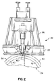
- a locating pin 164 is carried by the anvil and preferably is mounted for movement between a retracted position, shown in solid lines in Fig. 4, and an extended position illustrated in phantom in Fig. 4.
- the pin 164 can be moved between its two positions by air under pressure provided through fittings 166 and 168.
- the pin 164 is extended and the sheet is located on the drum by placing a perforation onto the pin. After the sheet is located on the drum the pin is retracted prior to movement of the ultrasonic sealing device over the anvil to effect sealing of the ends of the sheet together.
- the sheet holding means ' preferably comprises a vacuum system for applying a vacuum to the outer surface of the walls 40 and 70 of drum portions 24a, 24b and to the outer surface of the anvil 162. This can be accomplished by drilling a plurality of holes 172 in an axial direction through the semi-cylindrical walls 40 and 70 of the drum portions and through the anvil 162. The ends of each of the holes 172 nearest the face plate 60 are connected to a source of vacuum, shown diagramatically at 174 in Fig. 8. The other ends of the holes 172 opposite from the face plate 60 are closed by suitable plugs (not shown).
- a plurality of ports 176 are provided in walls 40, 70 and extend between the holes 172 and the outer surface of the walls.
- the poets 176 communicate with circumferentially extending grooves 178.
- the grooves 178 are generally parallel to each other with one set of grooves being offset in an axial direction from another set of grooves.
- a plurality of grooves 180 in the outer surface of walls 40, 70 extend in a direction perpendicular to the grooves 178. Grooves 180 are smaller than the grooves 178 and extend in an axial direction crossing a plurality of the grooves 178.
- vacuum from source 174 is be applied through holes 172, ports 176, and grooves 178, 180 throughout the surface area of the walls 40, 70 and the anvil 162 in order to hold sheet 126 in place on the drum.
- valves in the vacuum system enable vacuum to be applied separately to drum portion 24a and the left part of anvil 162, and to drum portion 24b and the right part of anvil 162. If desired the valves can apply vacuum sequentially to the left part of the anvil, then to a series of drum segments extending counter-clockwise (as viewed in Fig. 3) and finally to the right part of the anvil.
- camera system 30 and welding device 32 are supported by a frame 186.
- Frame 186 is mounted for reciprocal movement relative to frame 22 in eight and left directions as viewed in Fig. 1 so that camera system 30 and welding device 32 can be moved between their respective retracted positions shown in solid lines and extended positions illustrated in phantom.
- This sliding movement of the frame 186 and associated parts can be affected in any suitable manner, for example by a drive mechanism shown diagrammatically at 188.
- the drive mechanism 188 is under control of a logic and control unit 190 for the apparatus.
- the control unit 190 is also coupled to other parts of the apparatus, such as the motor for the differential screw assembly 90, sensing apparatus 118 and other elements of the apparatus in order to control operation of the apparatus 20.
- the apparatus is used for splicing together the ends of a sheet 26 having a photosensitive emulsion on one surface thereof.
- Sheets of this kind are formed into endless loops and used as a photoconductor in a electrographic copier/duplicator.
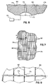
- the description of the operation will relate to a sheet 26 having a series of equally spaced perforations 28 along at least one side edge thereof wherein the perforations 28 are spaced apart by a distance 192 (Figs. 10-12).
- the loop For endless photoconductors with perforations it is important for the loop to be cylindrical in shape and for the perforations across the weld to be spaced apart the same distance 192 as the other perforations.
- the drum portion 24b is driven by differential screw assembly 90 to the "home" position.
- the differential screw drive is stopped when shaft collar 126 of sensing apparatus 118 is detected by optical sensing device 132.
- the upper edge of drum portion 24b is adjacent drum portion 24a.
- the circumference of the drum is equal to or slightly smaller than the circumference of the image loop that is to be formed.
- the sheet edge is substantially parallel to the edge of the drum portions 24a, 24b and the edge of the sheet is spaced from the edges of the drum portions as illustrated in Figs. 10-12.
- the locating pin 164 in the anvil is extended above the surface of the anvil and into a perforation spaced from the perforation 28a that is at the end of the sheet as shown in Fig. 10.
- the pin thus helps to establish the position of sheet on the anvil.
- vacuum is applied to the left side portion of anvil 162 from source 174 and vacuum in grooves 178, 180 will attract and hold the sheet 26 on the anvil.
- the locating pin 164 is retracted.
- the switch When the operator is satisfied that sheet 26 is properly positioned on the drum, the switch is closed and the control 190 activates the drive 188 to transport frame 186 to the right from its Fig. 1 position and thereby bring the vision camera system 30 and ultrasonic welding device 32 to the positions illustrated in dotted lines in Fig. 1. As this movement occurs the welding device 32 is elevated above the drum and the welding device is deactivated so that no weld is formed on the overlapping portions of the sheet 26.
- the field of view of the camera system comprises the circular area shown at 196 in Figs. 10-12.
- the field of view 196 includes perforations 28a, 28b but not the location pin 164.
- the vision camera system produces an electronic signal indicative of the relationship between perforations 28a and 28b in the area of the overlap. This signal is provided to the machine logic and control unit 190.
- the logic and control 190 will activate the drive to the differential screw assembly 90 to initiate movement of the drum portion 24b away from the anvil and drum portion 24a.
- This condition is illustrated in Fig. 11 where the drum portion 24b is separated from the anvil by a spacing designated 198.
- the spacing 194 between perforations 28a, 28b has increased but is not yet equal to the spacing 192 between adjacent perforations on sheet 26.
- the differential screw assembly 90 is driven until the condition shown in Fig. 12 is met, i.e., the perforations 28a, 28b are spaced by a distance equal to the spacing 192 between other perforations on the sheet.
- Control 190 then lowers the ultrasonic welding device 32 and, through drive 188, moves the welding device from its dotted line position in Fig. 1 to the solid line position while operating the welding device.
- the overlapping edges of the sheet 26 are welded together during this movement of the welding device. This results in an endless loop of material having a continuous weld line in the overlapped area and with the perforation pitch across the weld area being equal to the perforation pitch along other portions of the sheet of material.
- the controller 190 shuts off the vacuum to drum portions 24a, 24b and, if desired, a positive low pressure air can be provided through the vacuum ports to the drum to facilitate separation of the loop of material from the drum. Also, the controller will operate the differential screw assembly 90 in a direction to drive drum portion 24b toward drum portion 24a until the home position is reached so that the material 26 can be removed easily from the drum.
- drum portion 24b stop movement of drum portion 24b at its usual closed position and the vision camera system stops drum portion 24b at its usual open position.
- drum portion 24b is not stopped by the sensing device or by the camera system, it will be stopped in response to sensing device 134 detecting either collar 128 or collar 130.
- the drum 24 is removed from plate 60 and replaced with a drum of a different diameter.
- the apparatus and its operation have been described with respect to sheets of material 26 having features such as perforations 28 which need to be accurately located with respect to each other, the apparatus can also be used for sheets 26 not having features of this type. When perforations or other such features are not present on sheet 26, a drum of fixed diameter can be used.
- the apparatus of the present invention produces endless loops from sheet material at a single work station by a single operator. It also precisely locates perforations in the area of the overlap so that the pitch in the overlap area is the same as in other areas of the sheet. Another advantage of the apparatus is its ability to produce closed loops of material of a cylindrical shape. This results from the material being held by the drum in a cylindrical shape at the time the ends are welded together.
Landscapes
- Engineering & Computer Science (AREA)
- Mechanical Engineering (AREA)
- Lining Or Joining Of Plastics Or The Like (AREA)
- Shaping Of Tube Ends By Bending Or Straightening (AREA)
- Replacement Of Web Rolls (AREA)
- Tyre Moulding (AREA)
Claims (10)
- Vorrichtung zum Zusammenkleben der gegenüberliegenden Enden eines Blattes (26), um eine Endlosschleife aus diesem Material zu bilden, wobei das Blatt (26) identifizierbare Merkmale (28), die mit einem vorbestimmten Abstandsverhältnis entlang des Blattes angeordnet sind, aufweist, gekennzeichnet durch- eine im wesentlichen zylindrische Trommel (24) mit in axialer Richtung verlaufenden ersten und zweiten Kanten,- Mittel zum Verstellen der Trommelkanten relativ zueinander, um den Umfang der Trommel zu verändern,- Mittel (162, 174), die das Blatt auf der Trommel festhalten, wobei sich die gegenüberliegenden Enden des Blattes an den Trommelkanten überlappen,- Mittel (30) zum Abtasten des Abstandsverhältnisses zwischen den identifizierbaren Merkmalen an den sich überlappenden Enden des Blattes, während das Blatt auf der Trommel gehalten wird,- Steuermittel (190) zur Betätigung der Verstellmittel, um den Umfang der Trommel zu verändern und somit das Abstandsverhältnis zwischen den identifizierbaren Merkmalen an den sich überlappenden Enden zu verstellen, bis das vorbestimmte Abstandsverhältnis erreicht ist, und- Mittel (32) zum Zusammenkleben der gegenüberliegenden Enden des Blattes, sobald das vorbestimmte Abstandsverhältnis erreicht ist.
- Vorrichtung nach Anspruch 1, dadurch gekennzeichnet, daß die Trommel (24) einen ersten und zweiten Abschnitt (24a, 24b) mit jeweils einer halbzylindrischen Außenwand (40, 70) aufweist sowie Mittel (34), die die beiden Abschnitte scharnierartig verbinden, so daß der zweite Abschnitt relativ zum ersten Abschnitt bewegt werden kann.
- Vorrichtung nach Anspruch 2, dadurch gekennzeichnet, daß die Blatthaltemittel (162, 174) eine Vielzahl von in den Außenwänden (40, 70) angeordneten Nuten (180) sowie Mittel (172, 176, 178), die die Nuten mit einer Unterdruckquelle (174) verbinden, aufweisen.
- Vorrichtung nach Anspruch 2, dadurch gekennzeichnet, daß die Verstellmittel eine mit dem ersten und zweiten Trommelabschnitt (24a, 24b) verbundene und von den Scharniermitteln (34) beabstandete Ausgleichs-Schraubenanordnung (90) aufweisen sowie Mittel zum Bewegen der Anordnung in einer ersten und zweiten entgegengesetzten Richtung.
- Vorrichtung zum Zusammenkleben gegenüberliegender Enden eines blattförmigen Fotoleiters (26), um eine Endlosschleife zu bilden, wobei das Blatt (26) eine Vielzahl von in regelmäßigen Abständen angeordneten Perforationen (28) entlang einer Seitenkante des Blattes aufweist, gekennzeichnet durch- eine im wesentlichen zylindrische Trommel (24) mit einem ersten und zweiten Abschnitt (24a, 24b), die axial verlaufende, nebeneinander liegende Kanten aufweisen und zur Veränderung des Trommelumfangs relativ zueinander bewegbar sind,- Antriebsmittel (90), die die Trommelabschnitte aufeinander zu- und voneinander wegbewegen,- eine Unterdruckplatte (162, 174), die das Blatt auf der Trommel festhält, wobei sich die gegenüberliegenden Enden des Blattes an den Trommelkanten überlappen,- ein Kamerasystem (30) zum Abtasten des Abstandsverhältnisses zwischen den Perforationen an den sich überlappenden Enden des Blattes, während das Blatt auf der Trommel gehalten wird,- Steuermittel (190) zur Betätigung der Antriebsmittel, um den Umfang der Trommel zu verändern und somit den Abstand zwischen benachbarten Perforationen an den sich überlappenden Enden zu verstellen, bis ein vorbestimmtes Abstandsverhältnis erreicht ist, und- Mittel (32) zum Zusammenkleben der sich überlappenden Abschnitte der Blattenden, sobald das vorbestimmte Abstandsverhältnis erreicht ist.
- Vorrichtung nach Anspruch 5, dadurch gekennzeichnet, daß sie die Trommelabschnitte miteinander verbindende Scharniermittel (34) aufweist, die von den axial verlaufenden Kanten der Trommelabschnitte beabstandet sind, und daß die Antriebsmittel eine mit den Trommelabschnitten verbundene Ausgleichs-Schraubenanordnung (90) aufweisen, die eine relative Bewegung zwischen den Trommelabschnitten bewirkt.
- Vorrichtung nach Anspruch 6, dadurch gekennzeichnet, daß sie Mittel zum Abtasten der Bewegung der Trommelabschnittea) in eine erste relative Position, in der sich die Trommelkanten in ihrer größten Offenstellung befinden, undb) in eine zweite relative Position, in der die Trommelkanten am weitesten geschlossen sind, wobei die Abtastmittel der Ausgleichs-Schraubenanordnung (90) zugeordnet sind, so daß die Abtastmittel die relative Bewegung zwischen den Teilen der Ausgleichs-Schraubenanordnung ermitteln, umfaßt.
- Vorrichtung nach Anspruch 5, dadurch gekennzeichnet, daß die Verbindungsmittel eine Ultraschall-Schweißeinrichtung (32) aufweisen und die Vorrichtung Mittel umfaßt, mit denen die Schweißeinrichtung und das Kamerasystem für eine gemeinsame Bewegung zwischen a) einer ersten Stellung, in der sie von der Trommel beabstandet sind, um das Auflegen des Blattes auf die Trommel zu erleichtern, und b) einer zweiten Stellung, in der sie über der Trommel angeordnet sind, wobei sich das Kamerasystem über den Perforationen an einer Seitenkante des Blattes und die Schweißeinrichtung an der anderen Seitenkante des Blattes befinden, und wobei die Schweißeinrichtung (32) bei ihrer Bewegung von der zweiten zur ersten Stellung betätigt wird und die Blattenden mit Ultraschall zusammenschweißt.
- Vorrichtung nach Anspruch 8, dadurch gekennzeichnet, daß sie einen am ersten Trommelabschnitt angeordneten Amboß (162) aufweist, über den die Schweißeinrichtung bei ihrer Bewegung von der zweiten in die erste Stellung geführt wird, und daß sie einen Positionierstift (164) aufweist, der am ersten Trommelabschnitt angeordnet ist, mittels dessen eine am Blattende vorhandene Perforation auf dem Amboß festlegbar ist.
- Vorrichtung nach Anspruch 5, dadurch gekennzeichnet, daß sie einen an jeweils einer Seitenkante der Trommelabschnitte angeordneten Flansch (50, 80) und eine Vielzahl von an den Flanschen angebrachten Anschlägen (54, 84) umfaßt, so daß die eine Seitenkante des Blattes an die Anschläge angelegt werden kann und das Blatt somit auf der Trommel festlegbar ist.
Applications Claiming Priority (2)
| Application Number | Priority Date | Filing Date | Title |
|---|---|---|---|
| US07/353,833 US4957584A (en) | 1989-05-18 | 1989-05-18 | Apparatus for forming endless loops from sheet material |
| US353833 | 1989-05-18 |
Publications (2)
| Publication Number | Publication Date |
|---|---|
| EP0425656A1 EP0425656A1 (de) | 1991-05-08 |
| EP0425656B1 true EP0425656B1 (de) | 1993-04-07 |
Family
ID=23390771
Family Applications (1)
| Application Number | Title | Priority Date | Filing Date |
|---|---|---|---|
| EP90908905A Expired - Lifetime EP0425656B1 (de) | 1989-05-18 | 1990-05-16 | Vorrichtung zum formen von endlosschleifen aus einer folie |
Country Status (5)
| Country | Link |
|---|---|
| US (1) | US4957584A (de) |
| EP (1) | EP0425656B1 (de) |
| JP (1) | JP2803903B2 (de) |
| DE (1) | DE69001288T2 (de) |
| WO (1) | WO1990014211A1 (de) |
Families Citing this family (4)
| Publication number | Priority date | Publication date | Assignee | Title |
|---|---|---|---|---|
| JPH0397532A (ja) * | 1989-09-12 | 1991-04-23 | Bridgestone Corp | 円筒体の成型装置 |
| JPH09207223A (ja) * | 1996-02-02 | 1997-08-12 | Matsushita Electric Ind Co Ltd | 超音波溶着装置 |
| JP4323852B2 (ja) * | 2003-04-11 | 2009-09-02 | キヤノン株式会社 | トナー補給容器の製造方法 |
| JP4966716B2 (ja) * | 2007-04-06 | 2012-07-04 | ユニ・チャーム株式会社 | 加工装置 |
Family Cites Families (11)
| Publication number | Priority date | Publication date | Assignee | Title |
|---|---|---|---|---|
| NL6510032A (de) * | 1965-08-03 | 1967-02-06 | ||
| US3687786A (en) * | 1970-08-05 | 1972-08-29 | Eastman Kodak Co | Apparatus for splicing together the overlapping ends of photographic films |
| US3879256A (en) * | 1972-12-21 | 1975-04-22 | Crompton & Knowles Corp | Apparatus for vibration welding of sheet materials |
| DE2338908C3 (de) * | 1973-08-01 | 1981-06-04 | Elbatainer Kunststoff- Und Verpackungsgesellschaft Mbh, 7505 Ettlingen | Ultraschall-Schweißverfahren und -vorrichtung zum flüssigkeitsdichten Einschweißen eines verschließbaren Gießstutzens in einen dünnwandigen Flüssigkeitsbehälter sowie ein Gießstutzen hierfür |
| US3939033A (en) * | 1974-12-16 | 1976-02-17 | Branson Ultrasonics Corporation | Ultrasonic welding and cutting apparatus |
| US4357186A (en) * | 1980-06-17 | 1982-11-02 | The Mead Corporation | Machine and method for forming and applying carrying straps to article cartons |
| US4490199A (en) * | 1982-07-01 | 1984-12-25 | Allied Corporation | Method and apparatus for splicing polymeric webs |
| US4532166A (en) * | 1983-10-03 | 1985-07-30 | Xerox Corporation | Welding of web materials |
| US4683017A (en) * | 1985-11-25 | 1987-07-28 | Signode Corporation | Method and apparatus for forming a loop with end-gripped strap |
| JP2532446B2 (ja) * | 1986-03-27 | 1996-09-11 | ゼロツクス コ−ポレ−シヨン | 静電写真像形成ベルトの製造装置および方法 |
| US4838964A (en) * | 1987-03-20 | 1989-06-13 | Xerox Corporation | Process for preparing belts |
-
1989
- 1989-05-18 US US07/353,833 patent/US4957584A/en not_active Expired - Fee Related
-
1990
- 1990-05-16 WO PCT/US1990/002684 patent/WO1990014211A1/en not_active Ceased
- 1990-05-16 EP EP90908905A patent/EP0425656B1/de not_active Expired - Lifetime
- 1990-05-16 DE DE90908905T patent/DE69001288T2/de not_active Expired - Fee Related
- 1990-05-16 JP JP2508498A patent/JP2803903B2/ja not_active Expired - Lifetime
Also Published As
| Publication number | Publication date |
|---|---|
| JPH03506007A (ja) | 1991-12-26 |
| EP0425656A1 (de) | 1991-05-08 |
| US4957584A (en) | 1990-09-18 |
| DE69001288D1 (de) | 1993-05-13 |
| DE69001288T2 (de) | 1993-10-21 |
| JP2803903B2 (ja) | 1998-09-24 |
| WO1990014211A1 (en) | 1990-11-29 |
Similar Documents
| Publication | Publication Date | Title |
|---|---|---|
| EP0780331B1 (de) | Vorrichtung zum Ausrichten von Bahnen | |
| US5582399A (en) | Sheet feeding device having sheet edge sensor | |
| JP3447801B2 (ja) | シート位置決め装置 | |
| US5979732A (en) | Method and apparatus for pinless feeding of web to a utilization device | |
| JP2001520611A (ja) | エンドレスベルトをステアリングする装置及び方法 | |
| JPH02219785A (ja) | シュリンク包装装置 | |
| JPH01267242A (ja) | ウェブ供給装置の制御方法 | |
| US20060179796A1 (en) | Rolled article, and method of and apparatus for processing rolled article | |
| US4987448A (en) | Skewing detection mechanism for printer employing continuous recording form | |
| EP0425656B1 (de) | Vorrichtung zum formen von endlosschleifen aus einer folie | |
| JPH09169454A (ja) | 熱転写印刷紙を接合するための方法及びその装置 | |
| EP0622702B1 (de) | Messgerät zur Reduzierung von Blattnachweis- und Blattausrichtfehlern | |
| US5603790A (en) | Process for fabricating belts | |
| JP7024613B2 (ja) | シート残量検知装置およびスプライス装置ならびにシート残量検知方法およびスプライス方法 | |
| US20080023126A1 (en) | Method and Apparatus for Splicing Webs | |
| EP1348660B1 (de) | Vorrichtung zum Modifizieren der Position einer laufenden Papierbahn in einer papierverarbeitenden Maschine | |
| US6681671B2 (en) | Method and system for cutting puzzle cut petals in belts | |
| US6055399A (en) | Image forming apparatus | |
| EP0867757B1 (de) | Gerät und Verfahren zum Zentrieren einer Spule oder dergleichen | |
| SU1705118A1 (ru) | Устройство дл наложени полосового материала на сборочный барабан | |
| JPH1111791A (ja) | 検出器及びウェブ送りシステム | |
| CN100372354C (zh) | 圆柱形外表面扫描设备及其使用方法 | |
| JP2008127091A (ja) | フィルム供給装置およびこれを備えた包装装置 | |
| US4175689A (en) | Apparatus for centering strips in rolling mills and the like | |
| WO2024075673A1 (ja) | ラベル装着機 |
Legal Events
| Date | Code | Title | Description |
|---|---|---|---|
| PUAI | Public reference made under article 153(3) epc to a published international application that has entered the european phase |
Free format text: ORIGINAL CODE: 0009012 |
|
| AK | Designated contracting states |
Kind code of ref document: A1 Designated state(s): DE FR GB NL |
|
| 17P | Request for examination filed |
Effective date: 19910503 |
|
| 17Q | First examination report despatched |
Effective date: 19920703 |
|
| GRAA | (expected) grant |
Free format text: ORIGINAL CODE: 0009210 |
|
| AK | Designated contracting states |
Kind code of ref document: B1 Designated state(s): DE FR GB NL |
|
| REF | Corresponds to: |
Ref document number: 69001288 Country of ref document: DE Date of ref document: 19930513 |
|
| ET | Fr: translation filed | ||
| PLBE | No opposition filed within time limit |
Free format text: ORIGINAL CODE: 0009261 |
|
| STAA | Information on the status of an ep patent application or granted ep patent |
Free format text: STATUS: NO OPPOSITION FILED WITHIN TIME LIMIT |
|
| 26N | No opposition filed | ||
| PGFP | Annual fee paid to national office [announced via postgrant information from national office to epo] |
Ref country code: NL Payment date: 19970331 Year of fee payment: 8 |
|
| PGFP | Annual fee paid to national office [announced via postgrant information from national office to epo] |
Ref country code: GB Payment date: 19970408 Year of fee payment: 8 |
|
| PGFP | Annual fee paid to national office [announced via postgrant information from national office to epo] |
Ref country code: FR Payment date: 19970512 Year of fee payment: 8 |
|
| PGFP | Annual fee paid to national office [announced via postgrant information from national office to epo] |
Ref country code: DE Payment date: 19970528 Year of fee payment: 8 |
|
| PG25 | Lapsed in a contracting state [announced via postgrant information from national office to epo] |
Ref country code: GB Free format text: LAPSE BECAUSE OF NON-PAYMENT OF DUE FEES Effective date: 19980516 |
|
| PG25 | Lapsed in a contracting state [announced via postgrant information from national office to epo] |
Ref country code: FR Free format text: LAPSE BECAUSE OF NON-PAYMENT OF DUE FEES Effective date: 19980531 |
|
| PG25 | Lapsed in a contracting state [announced via postgrant information from national office to epo] |
Ref country code: NL Free format text: LAPSE BECAUSE OF NON-PAYMENT OF DUE FEES Effective date: 19981201 |
|
| GBPC | Gb: european patent ceased through non-payment of renewal fee |
Effective date: 19980516 |
|
| NLV4 | Nl: lapsed or anulled due to non-payment of the annual fee |
Effective date: 19981201 |
|
| PG25 | Lapsed in a contracting state [announced via postgrant information from national office to epo] |
Ref country code: DE Free format text: LAPSE BECAUSE OF NON-PAYMENT OF DUE FEES Effective date: 19990302 |
|
| REG | Reference to a national code |
Ref country code: FR Ref legal event code: ST |