EP0425368B1 - Von Gravitationswärmerohren gesteuerte Vorrichtungen zur Erzeugung von Kälte und/oder Wärme mittels einer Reaktion zwischen einem festen Körper und einem Gas - Google Patents
Von Gravitationswärmerohren gesteuerte Vorrichtungen zur Erzeugung von Kälte und/oder Wärme mittels einer Reaktion zwischen einem festen Körper und einem Gas Download PDFInfo
- Publication number
- EP0425368B1 EP0425368B1 EP90402982A EP90402982A EP0425368B1 EP 0425368 B1 EP0425368 B1 EP 0425368B1 EP 90402982 A EP90402982 A EP 90402982A EP 90402982 A EP90402982 A EP 90402982A EP 0425368 B1 EP0425368 B1 EP 0425368B1
- Authority
- EP
- European Patent Office
- Prior art keywords
- heat
- reactor
- temperature
- reactor chambers
- gravitational
- Prior art date
- Legal status (The legal status is an assumption and is not a legal conclusion. Google has not performed a legal analysis and makes no representation as to the accuracy of the status listed.)
- Expired - Lifetime
Links
Images


Classifications
-
- F—MECHANICAL ENGINEERING; LIGHTING; HEATING; WEAPONS; BLASTING
- F28—HEAT EXCHANGE IN GENERAL
- F28D—HEAT-EXCHANGE APPARATUS, NOT PROVIDED FOR IN ANOTHER SUBCLASS, IN WHICH THE HEAT-EXCHANGE MEDIA DO NOT COME INTO DIRECT CONTACT
- F28D15/00—Heat-exchange apparatus with the intermediate heat-transfer medium in closed tubes passing into or through the conduit walls ; Heat-exchange apparatus employing intermediate heat-transfer medium or bodies
- F28D15/02—Heat-exchange apparatus with the intermediate heat-transfer medium in closed tubes passing into or through the conduit walls ; Heat-exchange apparatus employing intermediate heat-transfer medium or bodies in which the medium condenses and evaporates, e.g. heat pipes
-
- F—MECHANICAL ENGINEERING; LIGHTING; HEATING; WEAPONS; BLASTING
- F25—REFRIGERATION OR COOLING; COMBINED HEATING AND REFRIGERATION SYSTEMS; HEAT PUMP SYSTEMS; MANUFACTURE OR STORAGE OF ICE; LIQUEFACTION SOLIDIFICATION OF GASES
- F25B—REFRIGERATION MACHINES, PLANTS OR SYSTEMS; COMBINED HEATING AND REFRIGERATION SYSTEMS; HEAT PUMP SYSTEMS
- F25B17/00—Sorption machines, plants or systems, operating intermittently, e.g. absorption or adsorption type
- F25B17/08—Sorption machines, plants or systems, operating intermittently, e.g. absorption or adsorption type the absorbent or adsorbent being a solid, e.g. salt
-
- Y—GENERAL TAGGING OF NEW TECHNOLOGICAL DEVELOPMENTS; GENERAL TAGGING OF CROSS-SECTIONAL TECHNOLOGIES SPANNING OVER SEVERAL SECTIONS OF THE IPC; TECHNICAL SUBJECTS COVERED BY FORMER USPC CROSS-REFERENCE ART COLLECTIONS [XRACs] AND DIGESTS
- Y02—TECHNOLOGIES OR APPLICATIONS FOR MITIGATION OR ADAPTATION AGAINST CLIMATE CHANGE
- Y02A—TECHNOLOGIES FOR ADAPTATION TO CLIMATE CHANGE
- Y02A30/00—Adapting or protecting infrastructure or their operation
- Y02A30/27—Relating to heating, ventilation or air conditioning [HVAC] technologies
-
- Y—GENERAL TAGGING OF NEW TECHNOLOGICAL DEVELOPMENTS; GENERAL TAGGING OF CROSS-SECTIONAL TECHNOLOGIES SPANNING OVER SEVERAL SECTIONS OF THE IPC; TECHNICAL SUBJECTS COVERED BY FORMER USPC CROSS-REFERENCE ART COLLECTIONS [XRACs] AND DIGESTS
- Y02—TECHNOLOGIES OR APPLICATIONS FOR MITIGATION OR ADAPTATION AGAINST CLIMATE CHANGE
- Y02B—CLIMATE CHANGE MITIGATION TECHNOLOGIES RELATED TO BUILDINGS, e.g. HOUSING, HOUSE APPLIANCES OR RELATED END-USER APPLICATIONS
- Y02B30/00—Energy efficient heating, ventilation or air conditioning [HVAC]
- Y02B30/62—Absorption based systems
Definitions
- the present invention relates to a device for producing cold and / or heat by solid-gas reaction and, more particularly, relates to an air conditioner with heat pumps.
- the reaction is exothermic in direction 1, which means that in this direction it produces heat and endothermic in direction 2, that is to say that in this direction it produces cold.
- Such a system allows energy storage in chemical form and has various fields of application.
- the system is called a "chemical heat pump”.
- Such a system also allows the production, from a heat source at temperature T's, of heat at temperature T'u such that: You> You
- the system is called "chemical thermo transformer”.
- the use of the heat or cold produced is simultaneous with the consumption of energy at high temperature (Ts, T's, T''s) or delayed over time (storage effect).
- French patent application No. 87 07210 discloses a device for producing cold and / or heat continuously which comprises two reactors containing the same solid compound, a condenser and an evaporator.
- this device is of limited effectiveness and requires a large number of components and actuating devices.
- Document EP-A-41244 describes a building heating system which comprises two similar chambers which are connected by a duct provided with a pump.
- One chamber is intended to contain a metal hydride, the other a metal capable of reacting to form a hydride.
- the present invention therefore aims to provide a device for producing cold and / or heat such as an air conditioner which is of improved efficiency and which requires a minimum number of actuating devices.
- the invention relates to a device for producing cold and / or heat by solid-gas reaction comprising reactor chambers, the device for producing cold and / or heat by solid-gas reaction comprising reactor chambers, each chamber containing a reagent capable of reacting by absorption with a gas according to an exothermic reaction, at least two of the reactor chambers being connected together by a gas passage, the device further comprising a passage for a fluid to be cooled and a passage for a fluid to be heated, characterized in that the reagent is formed by a mixture of a salt and an expanded product which is a good thermal conductor, and in that a heat pipe of the gravitational type ensures heat transfer between two reactor chambers, the reagents being such that the salt in one of the two reactor chambers allows absorption to be carried out at a temperature level higher than that necessary to effect desorption in the other of the two reactor chambers.
- FIG. 1 a heat pump air conditioner which, in the example illustrated, is intended to cool an air circulation in a room from 13 ° to 7 ° C.
- the air conditioner comprises a body 10 formed from a material having thermal insulating properties and in which four reactor chambers 12, 14, 16 and 18 are defined. Each reactor chamber is filled with a salt as will be described further on. detail below.
- the air conditioner includes heat transfer devices which are so-called “gravitational" heat pipes.
- a gravitational heat pipe comprises a tube, the lower part of which contains a fluid which, brought into contact with a heat source, evaporates towards the upper part of the tube, itself brought into contact with a more temperature source. cold, so as to condense the vapor in the form of liquid in this upper part. This liquid returns, by gravity, to the lower part of the heat pipe.
- Such a heat pipe forms a continuous system but requires a temperature gradient to function and, moreover, uses the phenomenon of gravity.
- heat pipes are thermal diodes which operate only when the temperature of their lower part is higher than that of their upper part.
- the present air conditioner includes seven gravitational heat pipes 20, 22, 24, 26, 28, 30 and 32 as will be described in more detail below.
- first air passage 34 comprising two sections of reduced diameter 36 and 38.
- a fan 40 arranged in section 36, is intended to circulate the ambient air in the passage 34 in the direction of the arrows.
- a first heat pipe 20 is mounted in the body 10 so that its lower part 42 projects into the reactor chamber 12. Its upper part 44, which is provided for example with fins 46 facilitating the transfer of heat, or any type of 'air exchanger, protrudes into the air passage 34.
- the heat pipes 22 and 24 are mounted between the reactor chambers 14 and 16 and the air passage 34. Each of these heat pipes 22 and 24 is provided with fins 46, the heat pipe 24 further comprising a control valve 48 intended to control the passage of fluid in the heat pipe 24 and, thus, its start-up.
- a second air passage 50 is formed in the body 10 of the air conditioner and has a reduced diameter section 52 in which is mounted a fan 54 intended to circulate the air to be cooled in the passage 50 in the direction of the arrows.
- the heat pipes 26 and 28 are mounted in the body 10 of the air conditioner so that their upper parts 56, 58 project respectively into the reactor chambers 12 and 14.
- the lower part of each heat pipe 26 and 28 projects into the passage of air 50 and comprises fins 60 in order to facilitate the transfer of heat between the heat pipes 26, 28 and the air to be cooled.
- the reactor chambers 16 and 18 are connected by the heat pipe 30, the upper part 62 of the latter projecting into the reactor chamber 16 and the lower part 64 being received in the reactor chamber 18.
- the heat pipe 30 is provided with a control valve 66.
- the body 10 of the air conditioner is provided with a third passage 68 in which is mounted a heat source which, in the example illustrated, is a boiler burner 70.
- the last heat pipe 32 is mounted with its upper part in the reactor chamber 18, its lower part, provided with fins 60, being received in the passage 68 next to the burner 70
- the reactor chambers 12 and 16 are in permanent communication via a passage 72.
- the reactor chambers 14 and 18 communicate by a passage 74.
- Each reactor chamber 12 to 18 is filled with an associated reagent containing a salt and which is chosen to ensure the predetermined function of the air conditioner.
- the reactor chambers are filled as follows.
- the reagent is formed from a mixture of a powdery salt and an expanded product which is a good thermal conductor.
- the expanded product is from the expanded graphic.
- the reactor chambers 12 and 14 are filled with a reagent containing a salt such as BaCl2 / NH3 which allows absorption-desorption cycling.
- the reactor chamber 16 contains a salt such as ZnCl2 / NH3 allowing absorption to be carried out at a temperature level greater than or equal to 45 ° C. at the pressure imposed by the reactor 12 in desorption.
- the reactor chamber 18 is filled with a reagent containing a salt, for example NiCl2 / NH3 which allows absorption to be carried out at a higher temperature level, at least 30 ° C, than the temperature level necessary to carry out the desorption of the reactor 16 at the pressure level imposed by the reactor 14 in absorption.
- Heat pipes 20 to 32 also have special characteristics which are selected to ensure the operation of the air conditioner under given conditions.
- the characteristics are as follows.
- Heat pipes 20 and 22 are simple gravitational heat pipes with a minimum operating range of 20 ° to 60 ° C, the extreme constraints being 20 ° C, the minimum outside air temperature and 60 ° C, the maximum salt temperature + 5 ° C.
- the heat pipe 24 is provided with a valve 48, the operating range is from 20 ° to 160 ° C, the extreme constraints being 20 ° C, the minimum outside air temperature, and 160 ° C maximum salt temperature + 5 ° C.
- the room air inlet temperature is 13 ° C
- the outside air temperature is 30 ° C
- the boiler temperature is 285 ° C.
- the valve 48 is open and the valve 66 is closed.
- the desorption occurring in the reactor 12 keeps it at a temperature between -5 ° C and 5 ° C.
- the production of cold is therefore ensured via the heat pipe 26.
- the absorption occurring in reactor 16 maintains it at a temperature between 35 ° C and 45 ° C.
- the heat pipe 24 evacuates the calories from this reaction in the outside air.
- the absorption occurring in reactor 14 maintains it at a temperature between 35 ° C and 55 ° C.
- the heat pipe 22 evacuates the calories from this reaction in the outside air.
- the heat pipe 32 brings the calories from the boiler 70 to the reactor 18 while maintaining it at a temperature between 250 ° C and 285 ° C, which ensures the desorption reaction of the latter.
- the opening of the valve 66, the closing of the valve 48 and the shutdown of the boiler allow the passage of the air conditioner to the next step.
- the reactor 18 being at a temperature higher than the reactor 16, the heat pipe 30 is in operation, the valve 66 being open.
- the heat pipe 30 therefore ensures the passage of the calories from the reactor 18 to the reactor 16, causing the cooling of the reactor 18 and the heating of the reactor 16.
- the cooling of the reactor 18 causes it to pass from the desorption condition to the absorption condition.
- Reactor 18 is connected to reactor 14 which is still under absorption conditions.
- the two reactors 14 and 18 are thus in absorption, which causes a drop in pressure in all of the reactors 14 and 18 by deficit of the absorbed gas.
- Reactor 14 will therefore soon be in desorption conditions and its temperature will therefore drop due to the effect endothermic of this desorption. From a temperature of around 35 ° to 40 ° C (end of absorption) the temperature will drop to a level below 30 ° C. Heat pipe 22 will then be out of function. Descending further, the temperature will drop to a level below 13 ° and the heat pipe 28 will operate, thus ensuring the production of cold air.
- Heating the reactor 16 causes it to pass from absorption condition to desorption condition.
- Reactor 16 is connected to reactor 12 which is still in desorption conditions.
- the two reactors 12 and 16 are therefore in desorption, which causes a pressure rise in all of the reactors 12 and 16 by accumulation of the desorbed gas.
- Reactor 12 will therefore soon be in absorption conditions. Its temperature will increase by the exothermic effect of this absorption. From a temperature of around 0 ° C to 5 ° C (end of desorption) the temperature will rise to a level above 13 ° C. Heat pipe 26 will then be out of function. Rising further, the temperature will rise above 30 ° C and the heat pipe 20 will operate ensuring the evacuation of the heat produced by absorption in the reactor 12.
- the air conditioner thus goes to the third step in which the heat pipes 20, 28 and 30 are in operating mode.
- the absorption occurring in reactor 12 maintains it at a temperature between 35 ° C and 55 ° C.
- the heat pipe 20 evacuates the calories from this reaction in the outside air.
- the desorption occurring in reactor 14 keeps it at a temperature between -5 ° C and 5 ° C.
- the production of cold is therefore ensured via the heat pipe 28.
- the operation of the heat pipe 30 allowing the passage, the calories from the reactor 18 to the reactor 16, the desorption occurring in the reactor 16 and the absorption occurring in the reactor 18 combine to maintain the reactor 16 at a temperature between 105 ° C and 140 ° C and the reactor 18 at a temperature between 120 ° C and 155 ° C. These conditions ensure the functioning of the system.
- the reactor 16 being at a temperature higher than that of the outside air, the opening of the valve 48 allows the operation of the heat pipe 24, which therefore ensures the cooling of the reactor 16.
- reactor 16 The cooling of the reactor 16 causes it to pass from the desorption condition to the absorption condition.
- Reactor 16 is connected to reactor 12 which is still in absorption conditions and the two reactors are therefore both in absorption. This causes a drop in pressure in all of the reactors 12 and 16 due to a deficit in the absorbed gas.
- the reactor 12 will therefore soon be in desorption conditions and its temperature will drop by the endothermic effect of this desorption. From a temperature of around 35 ° C to 40 ° C (end of absorption) the temperature will drop to a level below 30 ° C. Heat pipe 20 will then be out of function. Descending further, the temperature will drop to a level below 13 ° C and the heat pipe 26 will operate, thus ensuring the production of cold air.
- the operation of the boiler 70 allows the heating of the lower part of the heat pipe 32 to a temperature level of 285 ° C.
- the reactor 18 being at a temperature of approximately 120 ° C. to 140 ° C. (end of absorption), the heat pipe 32 is therefore in working order, which ensures the heating of the reactor 18.
- Heating the reactor 18 causes the transition from absorption condition to desorption condition.
- the reactor 18 being connected to the reactor 14 which is still in desorption conditions, the two reactors are therefore in the desorption condition. This causes a pressure rise in all of the reactors 14 and 18 by accumulation of the desorbed gas.
- the reactor 14 will therefore soon be in absorption conditions in which its temperature will increase by the exothermic effect of this absorption. From a temperature of around 0 ° C to 5 ° C (end of desorption) the temperature will rise to a level above 13 ° C and the heat pipe 28 will then be out of function. Rising further, the temperature will rise above 30 ° C and the heat pipe 22 will operate ensuring the evacuation of the heat produced by absorption in the reactor 14.
- the operation cycle of the air conditioner can resume from the first step.
- the present invention therefore makes it possible to produce a heat pump air conditioner which comprises a very small number of actuating devices. These are reduced to three, namely valves 48 and 66 and on / off control of the boiler 70.
- FIG. 4 A second embodiment of an air conditioner with heat pumps is shown in FIG. 4.
- This device differs from that described above in that it comprises two reactor chambers 80, 82, a condenser 84 and an evaporator 86.
- the device further comprises five gravitational heat pipes 88, 90, 92, 94 and 96 similar to those used in the air conditioner of Figure 1.
- the device of Figure 4 includes a fan 98 for making circulate ambient air between inlet 100 and outlet 102 in the direction of the arrows, as well as a burner 104 and a second fan 106 intended to circulate the air to be cooled.
- the heat pipes 90 and 92 are each provided with a control valve 91 and 93 intended to control the passage of fluid in the heat pipe and, thus, its start-up.
- the reactor chambers 80, 82, the condenser 84 and the evaporator 86 are connected together by a gas circuit 108 - represented by dotted lines - which comprises four non-return valves 110.
- the reactor chamber 80 is filled with a reagent containing a salt allowing absorption to be carried out at a temperature level greater than or equal to the temperature of the ambient air.
- the reactor chamber 82 is filled with a reagent containing a salt allowing absorption to be carried out at a temperature level higher than that necessary to effect the desorption of the reactor 80.
- the operation of the device is substantially similar to that of the device in FIG. 1, the operating cycle being controlled by starting the burner 104 and the selective opening of the valves 91 and 93.
- the use of gravitational heat pipes 88, 90, 92, 94 and 96 makes it possible to produce an air conditioner with heat pumps which comprises a very small number of actuation devices, three in this case; the valves 91 and 93 and the on / off control of the burner 104.
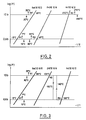
- FIG. 5 shows a third embodiment of an air conditioner with chemical heat pumps.
- This device comprises two reactor chambers 112 and 114 and is intended to produce simultaneously, but discontinuously, cold at the temperature T f and heat at the temperature Ta using the heat of a burner 115. Production can be provided continuously using two analog devices operating in opposite phase.
- This device comprises four gravitational heat pipes 116, 118, 120 and 122 of which only the heat pipe 118 is provided with a control valve 124.
- the reactor chamber 112 is filled with a reagent containing a salt allowing absorption to be carried out at a temperature level greater than or equal to the temperature Ta of the ambient air and at a pressure P b , and a desorption at a level of temperature lower than the temperature of the burner 115 and at a pressure P h .
- the reactor chamber 114 contains a reagent containing a salt making it possible to carry out an absorption at a temperature level higher than that necessary for carrying out the desorption of the reactor 112 at the pressure P h , and a desorption at a temperature below T f and at pressure P b .
- the salts having these described characteristics have equilibrium lines which intersect in the interval in question.
- control of the implementation of the gravitational heat pipes has been described as being carried out by control valves.
- an inert gas reservoir which contains a material capable of absorbing or desorbing the gas as a function of the temperature of the material.
- a material can for example be a zeolite.
- this type of control system is shown in FIG. 5 but it can be adapted to the devices in FIGS. 1 and 4.
- a tank 126 is placed next to the burner 115 and connected to the heat pipe 116 by a passage 128. At room temperature, the material in the tank 126 absorbs the inert gas and allows the heat pipe to function.
- the burner 115 is started, the temperature of the material increases and the inert gas is desorbed and passes into the interior of the heat pipe 116. The pressure of the gas prevents operation of the heat pipe thus stopping the heat transfer.
- the burner on / off control alone controls the operation of the air conditioner.
- the two control valves 48 and 66, and 91 and 93 can also be replaced by an inert gas system.
- the heat pipes 24 and 90 are controlled from the burner as was the case for the device in FIG. 5.
- the heat pipes 30 and 92 these are controlled by an inert gas tank which contains a resistance which is supplied during the burner shutdown phase. The operation of the heat pipes 30 and 92 is thus prevented during the shutdown of the burner. With such a system, the number of control devices is further reduced.
- the modulation of the production of cold can be achieved at low cost by the use of two gas flow control valves, located respectively in each of the passages 72 and 74, for the device of FIG. 1, or at the inlet of the evaporator and at the outlet of the condenser for the device of FIG. 4.
- the boiler can advantageously be replaced by a heat recovery system for the exhaust gases.
Landscapes
- Engineering & Computer Science (AREA)
- General Engineering & Computer Science (AREA)
- Physics & Mathematics (AREA)
- Thermal Sciences (AREA)
- Mechanical Engineering (AREA)
- Sustainable Development (AREA)
- Life Sciences & Earth Sciences (AREA)
- Sorption Type Refrigeration Machines (AREA)
- Physical Or Chemical Processes And Apparatus (AREA)
- Devices And Processes Conducted In The Presence Of Fluids And Solid Particles (AREA)
- Crucibles And Fluidized-Bed Furnaces (AREA)
- General Induction Heating (AREA)
- Production Of Liquid Hydrocarbon Mixture For Refining Petroleum (AREA)
Claims (7)
- Vorrichtung zur Erzeugung von Kälte und/oder Wärme durch eine Reaktion Feststoff-Gas mit Reaktorkammern (12, 14, 16, 18;80, 82; 112, 114), wobei jede Kammer ein Reagens enthält, das durch Absorption mit einem Gas gemäß einer exothermen Reaktion reagieren kann, wenigstens zwei der Reaktorkammern miteinander durch einen Gaskanal 72, 74; 108) verbunden sind und die Vorrichtung ferner einen Kanal für ein zu kühlendes Fluid und einen Kanal für ein zu erwärmendes Fluid aufweist, dadurch gekennzeichnet, daß das Reagens von einer Mischung eines Salzes und eines gut wärmeleitenden Schaumstoffs gebildet wird und daß ein Schwerkraftwärmerohr einen Wärmeübergang zwischen zwei Reaktorkammern (16, 18; 80, 82; 112, 114) gewährleistet, wobei die Reagenzien so beschaffen sind, daß das Salz in einer der beiden Reaktorkanmmern (16, 18; 80, 82; 112, 114) ermöglicht, daß eine Absorption auf einem Temperaturniveau bewirkt wird, das größer ist als das, welches zur Bewirkung der Desorption in der anderen der beiden Reaktorkammern erforderlich ist.
- Vorrichtung nach Anspruch 1, dadurch gekennzeichnet, daß sie vier Reaktorkammern (12, 14, 16, 18) umfaßt, die paarweise (12, 16; 14, 18) miteinander durch zugeordnete Känäle (72, 74) verbunden sind, wobei der Wärmeübergang zwischen jeder Reaktorkammer und einer externen Quelle nur durch ein Schwerkraft-Wärmerohr gewährleistet ist.
- Vorrichtung nach Anspruch 1, dadurch gekennzeichnet, daß sie zwei Reaktorkammern (80, 82), einen Kondensator (84) und einen Verdampfer (86) für das Gas aufweist, wobei der Wärmeübergang zwischen den Reaktorkammern (80, 82) und zwischen den Reaktorkammern, dem Kondensator, dem Verdampfer und den externen Quellen durch Schwerkraft-Wärmerohre (88-96) gewährleistet ist.
- Vorrichtung nach Anspruch 1, dadurch gekennzeichnet, daß sie zwei Reaktorkammern (112; 114) aufweist, wobei der Wärmeübergang zwischen den Reaktorkammern und zwischen den Reaktorkammern und den externen Quellen durch Schwerkraft-Wärmerohre gewährleistet ist.
- Vorrichtung nach Anspruch 2, dadurch gekennzeichnet, daß sie sieben Schwerkraft-Wärmerohre (20-32) aufweist, von denen nur zwei (24, 30) ein zugeordnetes Steuerventil (48; 66) aufweisen, das zum Steuern der Funktion der Vorrichtung bestimmt ist, und von denen das eine (30) zwischen zwei Reaktorkammern (16; 18) und das andere zwischen einer (16) der beiden Kammern und der Umgebungsluft angeordnet sind.
- Vorrichtung nach Anspruch 3, dadurch gekennzeichnet, daß sie fünf Schwerkraft-Wärmerohre (88-96) aufweist, von denen nur zwei (90; 92) ein zugeordnetes Steuerventil (91; 93) aufweisen und von denen das eine (92) zwischen zwei Reaktorkammern (80, 82) und das andere zwischen einer (80) der beiden Kammern und der Umgebungsluft angeordnet sind.
- Vorrichtung nach einem der Ansprüche 2 bis 4, dadurch gekennzeichnet, daß sie eine Einrichtung (126, 128) aufweist, die dazu bestimmt ist, ein zugehöriges Schwerkraft-Wärmerohr wirkungslos zu machen, wobei die Einrichtung (126, 128) einen Speicher (126) aufweist, der ein Inertgas als Funktion der Temperatur des Speichers absorbieren oder desorbieren kann, und der Speicher mit dem Schwerkraft-Wärmerohr verbunden ist.
Priority Applications (1)
| Application Number | Priority Date | Filing Date | Title |
|---|---|---|---|
| AT90402982T ATE89913T1 (de) | 1989-10-24 | 1990-10-23 | Von gravitationswaermerohren gesteuerte vorrichtungen zur erzeugung von kaelte und/oder waerme mittels einer reaktion zwischen einem festen koerper und einem gas. |
Applications Claiming Priority (2)
| Application Number | Priority Date | Filing Date | Title |
|---|---|---|---|
| FR8913913 | 1989-10-24 | ||
| FR8913913A FR2653541B1 (fr) | 1989-10-24 | 1989-10-24 | Dispositifs pour produire du froid et/ou de la chaleur par reaction solide-gaz geres par caloducs gravitationnels. |
Publications (2)
| Publication Number | Publication Date |
|---|---|
| EP0425368A1 EP0425368A1 (de) | 1991-05-02 |
| EP0425368B1 true EP0425368B1 (de) | 1993-05-26 |
Family
ID=9386714
Family Applications (1)
| Application Number | Title | Priority Date | Filing Date |
|---|---|---|---|
| EP90402982A Expired - Lifetime EP0425368B1 (de) | 1989-10-24 | 1990-10-23 | Von Gravitationswärmerohren gesteuerte Vorrichtungen zur Erzeugung von Kälte und/oder Wärme mittels einer Reaktion zwischen einem festen Körper und einem Gas |
Country Status (9)
| Country | Link |
|---|---|
| US (1) | US5083607A (de) |
| EP (1) | EP0425368B1 (de) |
| JP (1) | JP2627019B2 (de) |
| AT (1) | ATE89913T1 (de) |
| CA (1) | CA2028327C (de) |
| DE (1) | DE69001740T2 (de) |
| DK (1) | DK0425368T3 (de) |
| ES (1) | ES2043325T3 (de) |
| FR (1) | FR2653541B1 (de) |
Families Citing this family (13)
| Publication number | Priority date | Publication date | Assignee | Title |
|---|---|---|---|---|
| US5383341A (en) * | 1991-07-23 | 1995-01-24 | Uri Rapoport | Refrigeration, heating and air conditioning system for vehicles |
| IL98938A (en) * | 1991-07-23 | 1995-10-31 | Uri Rapoport | Refregeration heating and air conditioning system for vehicles |
| US5408847A (en) * | 1993-05-26 | 1995-04-25 | Erickson; Donald C. | Rotary solid sorption heat pump with embedded thermosyphons |
| US5916259A (en) * | 1995-09-20 | 1999-06-29 | Sun Microsystems, Inc. | Coaxial waveguide applicator for an electromagnetic wave-activated sorption system |
| FR2748093B1 (fr) * | 1996-04-25 | 1998-06-12 | Elf Aquitaine | Dispositif thermochimique pour produire du froid et/ou de la chaleur |
| CA2318858A1 (en) * | 1998-01-24 | 1999-07-29 | The University Of Nottingham | Heat transfer device |
| FR2774460B1 (fr) * | 1998-02-03 | 2000-03-24 | Elf Aquitaine | Procede de gestion d'une reaction thermochimique ou d'une adsorption solide-gaz |
| EP1022523A1 (de) | 1999-01-25 | 2000-07-26 | Bass Public Limited Company | Wärmeübertragungsvorrichtung |
| AU2003223103A1 (en) * | 2002-02-19 | 2003-09-09 | The Indian Institute Of Technology, Bombay | Energy efficient adsorption system |
| FR2877426B1 (fr) * | 2004-11-04 | 2007-03-02 | Centre Nat Rech Scient Cnrse | Production de froid a tres basse temperature dans un dispositif thermochimique. |
| WO2012031609A1 (en) | 2010-09-07 | 2012-03-15 | Johannes Kepler Universität Linz | Biodegradable, water soluble and ph responsive poly(organo)phosphazenes |
| FR2990267B1 (fr) * | 2012-05-03 | 2018-04-06 | Coldway | Dispositif et procede de production continue de froid par voie thermochimique |
| JP6551514B2 (ja) * | 2015-03-26 | 2019-07-31 | 株式会社村田製作所 | シート型ヒートパイプ |
Family Cites Families (16)
| Publication number | Priority date | Publication date | Assignee | Title |
|---|---|---|---|---|
| DE515311C (de) * | 1926-12-08 | 1931-01-02 | Platen Munters Refrigerating S | Nur in einer Richtung wirksame Waermeuebertragungsvorrichtung |
| DE549343C (de) * | 1927-02-19 | 1932-04-26 | Wulff Berzelius Normelli | Periodische Absorptionskaeltemaschine |
| US2088276A (en) * | 1931-12-08 | 1937-07-27 | Siemens Ag | System for the conversion of heat |
| US2068891A (en) * | 1932-05-12 | 1937-01-26 | Siemens Ag | Air-cooled reabsorption refrigerating apparatus of the intermittent type |
| DE678942C (de) * | 1932-12-22 | 1939-07-29 | Siemens Schuckertwerke Akt Ges | Einrichtung zur Waermeumwandlung |
| US2044951A (en) * | 1933-02-28 | 1936-06-23 | Servel Inc | Refrigeration |
| US4161211A (en) * | 1975-06-30 | 1979-07-17 | International Harvester Company | Methods of and apparatus for energy storage and utilization |
| GB1572737A (en) * | 1977-01-17 | 1980-08-06 | Exxon France | Heat pump |
| DE3020565A1 (de) * | 1980-05-30 | 1981-12-10 | Studiengesellschaft Kohle mbH, 4330 Mülheim | Verfahren und vorrichtung zur energiesparenden gewinnung von nutzwaerme aus der umgebung oder aus abfallwaerme |
| JPS58187769A (ja) * | 1982-04-26 | 1983-11-02 | 大阪瓦斯株式会社 | 自動車の冷房方法 |
| FR2547512B1 (fr) * | 1983-06-15 | 1985-09-27 | Elf Aquitaine | Procede de mise en oeuvre de reactions gaz-solide |
| DE3435630C1 (de) * | 1984-09-28 | 1986-05-22 | Dornier System Gmbh, 7990 Friedrichshafen | Periodische Absorptionskältemaschine |
| DE3518738A1 (de) * | 1985-05-24 | 1986-11-27 | Ruhrgas Ag, 4300 Essen | Verfahren und waermepumpe zur gewinnung von nutzwaerme |
| DE3604909C2 (de) * | 1986-02-17 | 1993-11-18 | Zeolith Tech | Verfahren zur Kälteerzeugung mit Hilfe von zwei periodisch arbeitenden Sorptions-Kälteerzeugern |
| US4848994A (en) * | 1987-11-02 | 1989-07-18 | Uwe Rockenfeller | System for low temperature refrigeration and chill storage using ammoniated complex compounds |
| JPH02259375A (ja) * | 1989-03-31 | 1990-10-22 | Sanyo Electric Co Ltd | 金属水素化物利用の冷却装置 |
-
1989
- 1989-10-24 FR FR8913913A patent/FR2653541B1/fr not_active Expired - Fee Related
-
1990
- 1990-10-22 US US07/600,833 patent/US5083607A/en not_active Expired - Fee Related
- 1990-10-23 CA CA002028327A patent/CA2028327C/fr not_active Expired - Fee Related
- 1990-10-23 DK DK90402982.4T patent/DK0425368T3/da active
- 1990-10-23 JP JP2283586A patent/JP2627019B2/ja not_active Expired - Lifetime
- 1990-10-23 AT AT90402982T patent/ATE89913T1/de not_active IP Right Cessation
- 1990-10-23 ES ES90402982T patent/ES2043325T3/es not_active Expired - Lifetime
- 1990-10-23 EP EP90402982A patent/EP0425368B1/de not_active Expired - Lifetime
- 1990-10-23 DE DE90402982T patent/DE69001740T2/de not_active Expired - Fee Related
Also Published As
| Publication number | Publication date |
|---|---|
| FR2653541B1 (fr) | 1995-02-10 |
| FR2653541A1 (fr) | 1991-04-26 |
| JPH03181758A (ja) | 1991-08-07 |
| EP0425368A1 (de) | 1991-05-02 |
| CA2028327C (fr) | 1999-02-16 |
| DE69001740T2 (de) | 1993-11-25 |
| DK0425368T3 (da) | 1993-10-11 |
| US5083607A (en) | 1992-01-28 |
| DE69001740D1 (de) | 1993-07-01 |
| ES2043325T3 (es) | 1993-12-16 |
| CA2028327A1 (fr) | 1991-04-25 |
| ATE89913T1 (de) | 1993-06-15 |
| JP2627019B2 (ja) | 1997-07-02 |
Similar Documents
| Publication | Publication Date | Title |
|---|---|---|
| EP0425368B1 (de) | Von Gravitationswärmerohren gesteuerte Vorrichtungen zur Erzeugung von Kälte und/oder Wärme mittels einer Reaktion zwischen einem festen Körper und einem Gas | |
| EP0382586B1 (de) | Vorrichtung zum Erzeugen von Kälte und/oder Wärme mittels einer Reaktion zwischen einem festen Körper und einem Gas | |
| EP0622593B1 (de) | Ein festes Sorptionsmittel verwendende Kühl- und Heizvorrichtung | |
| EP0550748B1 (de) | Kaelteerzeugungsanlage mittels einer reaktion zwischen einem festen koerper und einem gas, und von kuehlmitteln versehener reaktor | |
| WO1981000904A1 (fr) | Procede et dispositif de refrigeration | |
| EP1809955B1 (de) | Erzeugung von Tiefkühlung in einer thermochemischen Vorrichtung. | |
| EP0810410B1 (de) | Steuerungsverfahren einer thermochemischen Reaktion oder einer Adsorption zwischen einem festen Körper und einem Gas | |
| EP0580848B1 (de) | Vorrichtung zum Erzeugen von Kälte und/oder Wärme mittels einer Reaktion zwischen einem festen Körper und einem Gas | |
| FR3082608A1 (fr) | Systeme comprenant une machine a absorption pour la production de froid a partir de la chaleur fatale de gaz d'echappement d'un vehicule comprenant un module de stockage de l'energie thermique | |
| CA2161578C (fr) | Reactif pour systemes thermochimiques et systeme thermochimique destine a utiliser un tel reactif | |
| FR2748093A1 (fr) | Dispositif thermochimique pour produire du froid et/ou de la chaleur | |
| CA2318965C (fr) | Procede de gestion d'une reaction thermochimique ou d'une adsorption solide-gaz | |
| EP3584517B1 (de) | System, das eine absorptionsmaschine für die kälteerzeugung aus der abwärme vom abgas eines fahrzeugs und ein wärmeenergie-speichermodul umfasst, verfahren zur verwendung des systems und eine verwendung des systems | |
| EP3682176B1 (de) | Verfahren zum kühlen einer isothermischen box auf eine zieltemperatur und zugehörige anlage | |
| FR2730299A1 (fr) | Echangeur de chaleur diphasique a temperature controlee | |
| FR2748094A1 (fr) | Dispositif thermochimique pour produire du froid et/ou de la chaleur | |
| FR2629575A1 (fr) | Caloduc chimique, procede de regeneration d'un tel caloduc et utilisation de ce caloduc | |
| EP1809956B1 (de) | Erzeugung von tiefkühlung in einer thermochemischen vorrichtung | |
| WO1993003313A1 (fr) | Installation pour produire du froid par reaction solide/gaz, le reacteur comportant des moyens de chauffage | |
| FR2666140A1 (fr) | Pompe a chaleur a cycle de desorption-adsorption a fonctionnement pseudo-continu. | |
| WO1998023906A1 (fr) | Thermo-frigopompe |
Legal Events
| Date | Code | Title | Description |
|---|---|---|---|
| PUAI | Public reference made under article 153(3) epc to a published international application that has entered the european phase |
Free format text: ORIGINAL CODE: 0009012 |
|
| 17P | Request for examination filed |
Effective date: 19901027 |
|
| AK | Designated contracting states |
Kind code of ref document: A1 Designated state(s): AT BE CH DE DK ES FR GB IT LI LU NL SE |
|
| 17Q | First examination report despatched |
Effective date: 19920110 |
|
| GRAA | (expected) grant |
Free format text: ORIGINAL CODE: 0009210 |
|
| AK | Designated contracting states |
Kind code of ref document: B1 Designated state(s): AT BE CH DE DK ES FR GB IT LI LU NL SE |
|
| REF | Corresponds to: |
Ref document number: 89913 Country of ref document: AT Date of ref document: 19930615 Kind code of ref document: T |
|
| REF | Corresponds to: |
Ref document number: 69001740 Country of ref document: DE Date of ref document: 19930701 |
|
| ITF | It: translation for a ep patent filed |
Owner name: ING. A. GIAMBROCONO & C. S.R.L. |
|
| GBT | Gb: translation of ep patent filed (gb section 77(6)(a)/1977) |
Effective date: 19930901 |
|
| REG | Reference to a national code |
Ref country code: DK Ref legal event code: T3 |
|
| EPTA | Lu: last paid annual fee | ||
| REG | Reference to a national code |
Ref country code: ES Ref legal event code: FG2A Ref document number: 2043325 Country of ref document: ES Kind code of ref document: T3 |
|
| PLBE | No opposition filed within time limit |
Free format text: ORIGINAL CODE: 0009261 |
|
| STAA | Information on the status of an ep patent application or granted ep patent |
Free format text: STATUS: NO OPPOSITION FILED WITHIN TIME LIMIT |
|
| 26N | No opposition filed | ||
| EAL | Se: european patent in force in sweden |
Ref document number: 90402982.4 |
|
| REG | Reference to a national code |
Ref country code: FR Ref legal event code: CL |
|
| PGFP | Annual fee paid to national office [announced via postgrant information from national office to epo] |
Ref country code: LU Payment date: 19980928 Year of fee payment: 9 |
|
| PGFP | Annual fee paid to national office [announced via postgrant information from national office to epo] |
Ref country code: DK Payment date: 19980929 Year of fee payment: 9 |
|
| PGFP | Annual fee paid to national office [announced via postgrant information from national office to epo] |
Ref country code: CH Payment date: 19981002 Year of fee payment: 9 |
|
| PGFP | Annual fee paid to national office [announced via postgrant information from national office to epo] |
Ref country code: BE Payment date: 19981016 Year of fee payment: 9 |
|
| PG25 | Lapsed in a contracting state [announced via postgrant information from national office to epo] |
Ref country code: LU Free format text: LAPSE BECAUSE OF NON-PAYMENT OF DUE FEES Effective date: 19991023 Ref country code: DK Free format text: LAPSE BECAUSE OF NON-PAYMENT OF DUE FEES Effective date: 19991023 |
|
| PG25 | Lapsed in a contracting state [announced via postgrant information from national office to epo] |
Ref country code: LI Free format text: LAPSE BECAUSE OF NON-PAYMENT OF DUE FEES Effective date: 19991031 Ref country code: CH Free format text: LAPSE BECAUSE OF NON-PAYMENT OF DUE FEES Effective date: 19991031 Ref country code: BE Free format text: LAPSE BECAUSE OF NON-PAYMENT OF DUE FEES Effective date: 19991031 |
|
| BERE | Be: lapsed |
Owner name: SOC. NATIONALE ELF AQUITAINE Effective date: 19991031 |
|
| REG | Reference to a national code |
Ref country code: CH Ref legal event code: PL |
|
| REG | Reference to a national code |
Ref country code: DK Ref legal event code: EBP |
|
| NLS | Nl: assignments of ep-patents |
Owner name: CENTRE NATIONAL DE LA RECHERCHE SCIENTIFIQUE |
|
| NLT1 | Nl: modifications of names registered in virtue of documents presented to the patent office pursuant to art. 16 a, paragraph 1 |
Owner name: ELF AQUITAINE |
|
| PGFP | Annual fee paid to national office [announced via postgrant information from national office to epo] |
Ref country code: AT Payment date: 20010925 Year of fee payment: 12 |
|
| PGFP | Annual fee paid to national office [announced via postgrant information from national office to epo] |
Ref country code: SE Payment date: 20010926 Year of fee payment: 12 |
|
| PGFP | Annual fee paid to national office [announced via postgrant information from national office to epo] |
Ref country code: NL Payment date: 20010927 Year of fee payment: 12 |
|
| PGFP | Annual fee paid to national office [announced via postgrant information from national office to epo] |
Ref country code: GB Payment date: 20010928 Year of fee payment: 12 |
|
| PGFP | Annual fee paid to national office [announced via postgrant information from national office to epo] |
Ref country code: DE Payment date: 20011004 Year of fee payment: 12 |
|
| PGFP | Annual fee paid to national office [announced via postgrant information from national office to epo] |
Ref country code: ES Payment date: 20011018 Year of fee payment: 12 |
|
| PGFP | Annual fee paid to national office [announced via postgrant information from national office to epo] |
Ref country code: FR Payment date: 20011026 Year of fee payment: 12 |
|
| REG | Reference to a national code |
Ref country code: GB Ref legal event code: IF02 |
|
| REG | Reference to a national code |
Ref country code: GB Ref legal event code: 732E |
|
| PG25 | Lapsed in a contracting state [announced via postgrant information from national office to epo] |
Ref country code: GB Free format text: LAPSE BECAUSE OF NON-PAYMENT OF DUE FEES Effective date: 20021023 Ref country code: AT Free format text: LAPSE BECAUSE OF NON-PAYMENT OF DUE FEES Effective date: 20021023 |
|
| PG25 | Lapsed in a contracting state [announced via postgrant information from national office to epo] |
Ref country code: SE Free format text: LAPSE BECAUSE OF NON-PAYMENT OF DUE FEES Effective date: 20021024 Ref country code: ES Free format text: LAPSE BECAUSE OF NON-PAYMENT OF DUE FEES Effective date: 20021024 |
|
| PG25 | Lapsed in a contracting state [announced via postgrant information from national office to epo] |
Ref country code: NL Free format text: LAPSE BECAUSE OF NON-PAYMENT OF DUE FEES Effective date: 20030501 Ref country code: DE Free format text: LAPSE BECAUSE OF NON-PAYMENT OF DUE FEES Effective date: 20030501 |
|
| EUG | Se: european patent has lapsed | ||
| GBPC | Gb: european patent ceased through non-payment of renewal fee |
Effective date: 20021023 |
|
| PG25 | Lapsed in a contracting state [announced via postgrant information from national office to epo] |
Ref country code: FR Free format text: LAPSE BECAUSE OF NON-PAYMENT OF DUE FEES Effective date: 20030630 |
|
| NLV4 | Nl: lapsed or anulled due to non-payment of the annual fee |
Effective date: 20030501 |
|
| REG | Reference to a national code |
Ref country code: FR Ref legal event code: ST |
|
| REG | Reference to a national code |
Ref country code: ES Ref legal event code: FD2A Effective date: 20031112 |
|
| PG25 | Lapsed in a contracting state [announced via postgrant information from national office to epo] |
Ref country code: IT Free format text: LAPSE BECAUSE OF NON-PAYMENT OF DUE FEES;WARNING: LAPSES OF ITALIAN PATENTS WITH EFFECTIVE DATE BEFORE 2007 MAY HAVE OCCURRED AT ANY TIME BEFORE 2007. THE CORRECT EFFECTIVE DATE MAY BE DIFFERENT FROM THE ONE RECORDED. Effective date: 20051023 |