EP0425363B1 - Vapor pump with countercurrent exchanger for air and combustion products without intermediate fluid - Google Patents
Vapor pump with countercurrent exchanger for air and combustion products without intermediate fluid Download PDFInfo
- Publication number
- EP0425363B1 EP0425363B1 EP90402973A EP90402973A EP0425363B1 EP 0425363 B1 EP0425363 B1 EP 0425363B1 EP 90402973 A EP90402973 A EP 90402973A EP 90402973 A EP90402973 A EP 90402973A EP 0425363 B1 EP0425363 B1 EP 0425363B1
- Authority
- EP
- European Patent Office
- Prior art keywords
- air
- enclosure
- tubes
- water
- combustion products
- Prior art date
- Legal status (The legal status is an assumption and is not a legal conclusion. Google has not performed a legal analysis and makes no representation as to the accuracy of the status listed.)
- Expired - Lifetime
Links
Images


Classifications
-
- F—MECHANICAL ENGINEERING; LIGHTING; HEATING; WEAPONS; BLASTING
- F23—COMBUSTION APPARATUS; COMBUSTION PROCESSES
- F23L—SUPPLYING AIR OR NON-COMBUSTIBLE LIQUIDS OR GASES TO COMBUSTION APPARATUS IN GENERAL ; VALVES OR DAMPERS SPECIALLY ADAPTED FOR CONTROLLING AIR SUPPLY OR DRAUGHT IN COMBUSTION APPARATUS; INDUCING DRAUGHT IN COMBUSTION APPARATUS; TOPS FOR CHIMNEYS OR VENTILATING SHAFTS; TERMINALS FOR FLUES
- F23L15/00—Heating of air supplied for combustion
- F23L15/04—Arrangements of recuperators
-
- F—MECHANICAL ENGINEERING; LIGHTING; HEATING; WEAPONS; BLASTING
- F24—HEATING; RANGES; VENTILATING
- F24H—FLUID HEATERS, e.g. WATER OR AIR HEATERS, HAVING HEAT-GENERATING MEANS, e.g. HEAT PUMPS, IN GENERAL
- F24H1/00—Water heaters, e.g. boilers, continuous-flow heaters or water-storage heaters
- F24H1/10—Continuous-flow heaters, i.e. heaters in which heat is generated only while the water is flowing, e.g. with direct contact of the water with the heating medium
- F24H1/107—Continuous-flow heaters, i.e. heaters in which heat is generated only while the water is flowing, e.g. with direct contact of the water with the heating medium using fluid fuel
-
- F—MECHANICAL ENGINEERING; LIGHTING; HEATING; WEAPONS; BLASTING
- F24—HEATING; RANGES; VENTILATING
- F24H—FLUID HEATERS, e.g. WATER OR AIR HEATERS, HAVING HEAT-GENERATING MEANS, e.g. HEAT PUMPS, IN GENERAL
- F24H8/00—Fluid heaters characterised by means for extracting latent heat from flue gases by means of condensation
- F24H8/003—Fluid heaters characterised by means for extracting latent heat from flue gases by means of condensation having means for moistening the combustion air with condensate from the combustion gases
-
- F—MECHANICAL ENGINEERING; LIGHTING; HEATING; WEAPONS; BLASTING
- F28—HEAT EXCHANGE IN GENERAL
- F28D—HEAT-EXCHANGE APPARATUS, NOT PROVIDED FOR IN ANOTHER SUBCLASS, IN WHICH THE HEAT-EXCHANGE MEDIA DO NOT COME INTO DIRECT CONTACT
- F28D5/00—Heat-exchange apparatus having stationary conduit assemblies for one heat-exchange medium only, the media being in contact with different sides of the conduit wall, using the cooling effect of natural or forced evaporation
- F28D5/02—Heat-exchange apparatus having stationary conduit assemblies for one heat-exchange medium only, the media being in contact with different sides of the conduit wall, using the cooling effect of natural or forced evaporation in which the evaporating medium flows in a continuous film or trickles freely over the conduits
-
- F—MECHANICAL ENGINEERING; LIGHTING; HEATING; WEAPONS; BLASTING
- F28—HEAT EXCHANGE IN GENERAL
- F28D—HEAT-EXCHANGE APPARATUS, NOT PROVIDED FOR IN ANOTHER SUBCLASS, IN WHICH THE HEAT-EXCHANGE MEDIA DO NOT COME INTO DIRECT CONTACT
- F28D7/00—Heat-exchange apparatus having stationary tubular conduit assemblies for both heat-exchange media, the media being in contact with different sides of a conduit wall
- F28D7/16—Heat-exchange apparatus having stationary tubular conduit assemblies for both heat-exchange media, the media being in contact with different sides of a conduit wall the conduits being arranged in parallel spaced relation
-
- F—MECHANICAL ENGINEERING; LIGHTING; HEATING; WEAPONS; BLASTING
- F28—HEAT EXCHANGE IN GENERAL
- F28F—DETAILS OF HEAT-EXCHANGE AND HEAT-TRANSFER APPARATUS, OF GENERAL APPLICATION
- F28F13/00—Arrangements for modifying heat-transfer, e.g. increasing, decreasing
- F28F13/04—Arrangements for modifying heat-transfer, e.g. increasing, decreasing by preventing the formation of continuous films of condensate on heat-exchange surfaces, e.g. by promoting droplet formation
-
- Y—GENERAL TAGGING OF NEW TECHNOLOGICAL DEVELOPMENTS; GENERAL TAGGING OF CROSS-SECTIONAL TECHNOLOGIES SPANNING OVER SEVERAL SECTIONS OF THE IPC; TECHNICAL SUBJECTS COVERED BY FORMER USPC CROSS-REFERENCE ART COLLECTIONS [XRACs] AND DIGESTS
- Y02—TECHNOLOGIES OR APPLICATIONS FOR MITIGATION OR ADAPTATION AGAINST CLIMATE CHANGE
- Y02B—CLIMATE CHANGE MITIGATION TECHNOLOGIES RELATED TO BUILDINGS, e.g. HOUSING, HOUSE APPLIANCES OR RELATED END-USER APPLICATIONS
- Y02B30/00—Energy efficient heating, ventilation or air conditioning [HVAC]
-
- Y—GENERAL TAGGING OF NEW TECHNOLOGICAL DEVELOPMENTS; GENERAL TAGGING OF CROSS-SECTIONAL TECHNOLOGIES SPANNING OVER SEVERAL SECTIONS OF THE IPC; TECHNICAL SUBJECTS COVERED BY FORMER USPC CROSS-REFERENCE ART COLLECTIONS [XRACs] AND DIGESTS
- Y02—TECHNOLOGIES OR APPLICATIONS FOR MITIGATION OR ADAPTATION AGAINST CLIMATE CHANGE
- Y02E—REDUCTION OF GREENHOUSE GAS [GHG] EMISSIONS, RELATED TO ENERGY GENERATION, TRANSMISSION OR DISTRIBUTION
- Y02E20/00—Combustion technologies with mitigation potential
- Y02E20/34—Indirect CO2mitigation, i.e. by acting on non CO2directly related matters of the process, e.g. pre-heating or heat recovery
-
- Y—GENERAL TAGGING OF NEW TECHNOLOGICAL DEVELOPMENTS; GENERAL TAGGING OF CROSS-SECTIONAL TECHNOLOGIES SPANNING OVER SEVERAL SECTIONS OF THE IPC; TECHNICAL SUBJECTS COVERED BY FORMER USPC CROSS-REFERENCE ART COLLECTIONS [XRACs] AND DIGESTS
- Y10—TECHNICAL SUBJECTS COVERED BY FORMER USPC
- Y10S—TECHNICAL SUBJECTS COVERED BY FORMER USPC CROSS-REFERENCE ART COLLECTIONS [XRACs] AND DIGESTS
- Y10S122/00—Liquid heaters and vaporizers
- Y10S122/01—Air heater
-
- Y—GENERAL TAGGING OF NEW TECHNOLOGICAL DEVELOPMENTS; GENERAL TAGGING OF CROSS-SECTIONAL TECHNOLOGIES SPANNING OVER SEVERAL SECTIONS OF THE IPC; TECHNICAL SUBJECTS COVERED BY FORMER USPC CROSS-REFERENCE ART COLLECTIONS [XRACs] AND DIGESTS
- Y10—TECHNICAL SUBJECTS COVERED BY FORMER USPC
- Y10S—TECHNICAL SUBJECTS COVERED BY FORMER USPC CROSS-REFERENCE ART COLLECTIONS [XRACs] AND DIGESTS
- Y10S165/00—Heat exchange
- Y10S165/909—Regeneration
Definitions
- the present invention relates to a water vapor pump constituted by a mass and heat exchanger ensuring energy transfers on the one hand between combustion products from a thermal process and having passed through a first condenser and on the other hand, the incoming combustion air.
- Document FR-A-2 446 460 has thus proposed a condensation heating installation comprising a heat exchanger-recuperator for thermally coupling the combustion air necessary for the heat generator with combustion products from the heat generator, humidification means being provided for removing at least part of the condensates from the combustion products and for bringing these condensates into contact with the combustion air.
- This known exchanger comprises a plurality of juxtaposed compartments separated by vertical partitions and communicating at their ends with lower and upper chambers, a first series of alternating compartments being in communication at a first end with a first lower chamber and at a second end with a first upper chamber while the compartments immediately adjacent to the alternating compartments of the first series communicate with a second upper chamber at their end close to said first end and with a second lower chamber at their end close to said second end.
- the alternating compartments communicating with the first upper and lower chambers are traversed by air to be heated while the alternating compartments communicating with the second upper and lower chambers are traversed by products of combustion.
- a first series of condensate supply ramps is installed at the upper end of the compartments of the first series while a second series of condensate supply ramps is installed at the upper end of the compartments of the second series.
- Such a type of mass and heat exchanger proves to be very bulky, difficult to produce and costly if it is desired to obtain high efficiency.
- it ensures cross-flow exchanges and leads most of the time to excessive humidification of the fumes or to a phenomenon of condensate runoff on either side of the walls of the exchanger which often causes a decrease in the efficiency of the heat exchange.
- condensate control is difficult to carry out and, moreover, auxiliary pumping or ventilation installations involve energy consumption which is often not negligible.
- Document FR-A-2 508 616 has also proposed a device for treating relatively hot and humid gases, such as fumes, and relatively dry and fresh gases, such as oxidizing gases from a fireplace, for recover the heat and possibly the condensates from the smoke and reheat and humidify the combustion air.
- This known treatment device however uses two separate enclosures traversed one by hot and humid gases and the other by relatively dry and fresh gases, each of the enclosures comprising at its upper part means for spraying liquids constituted by condensates recovered during treatment.
- such a treatment device is bulky due to the presence of two enclosures and is of an efficiency which, although acceptable, remains limited.
- Document CH-A-148723 also discloses a boiler installation in which dry combustion air is preheated and also preheated water is injected into this combustion air so as to obtain humidified combustion air, the preheating level is limited.
- the present invention aims to remedy the aforementioned drawbacks and to make it possible to obtain increased efficiency in recycling the enthalpy of the combustion products with a heat and mass exchanger, the size of which as well as the manufacturing and operating costs are reduced.
- Another object of the invention is to produce a heat and mass exchanger, also known as a steam pump, which can be used in combination with various thermal processes, whether or not associated with condensers, without the need for delicate adaptations. , in particular in the case of large installations, such as boiler rooms using condensing boilers.
- a water vapor pump constituted by a mass and heat exchanger ensuring energy transfers between on the one hand combustion products from a thermal process and having passed through a first condenser and on the other hand, the incoming combustion air, comprising an external enclosure, a set of compartments forming a heat exchanger arranged inside the enclosure in the longitudinal direction thereof opening at their ends at a first radial plane and d '' a second radial plane, of way of defining between said radial planes a first gaseous fluid circulation circuit inside the compartments and a second separate gaseous fluid circulation circuit inside the enclosure but outside the compartments, an orifice introduction of a first gaseous fluid inside the enclosure into said second circuit, a discharge orifice outside the enclosure of said first gaseous fluid circulating in said second circuit, an orifice for introducing a second gaseous fluid inside the enclosure in said first circuit and a discharge orifice outside the enclosure of said second gaseous fluid flowing against the current in said first circuit, one of the
- the tubes have smooth walls and are advantageously constituted by tubes with a large exchange surface, such as tubes in the shape of a "bean" section having two portions of larger diameter placed in communication using a portion close bond.
- the tubes of the air-combustion products exchanger can be made of a synthetic material, such as polyvinylidene fluoride (PVDF) or polyvinyl chloride (PVC) but can also be metallic. , in stainless steel for example.
- PVDF polyvinylidene fluoride
- PVC polyvinyl chloride
- each nozzle forming an element of the humidification means produces a jet in the form of a solid cone, and comprises a multiplicity of outlet orifices ensuring the spraying of water according to a fine mist. throughout the volume of a cone, the top of which is substantially formed by the top of the nozzle.
- the different nozzles are arranged so that the Water spray cones overlap.
- the enclosure is arranged vertically and the humidification means comprise a first set of nozzles oriented downwards and arranged at the upper part of the enclosure so as to spray water over all the section of the enclosure located above the end of the tubes constituting the air-smoke exchanger and a second set of nozzles oriented upwards and arranged at the bottom of the enclosure so as to spray water over the entire section of the enclosure located below the tubes.
- air is introduced into the first gaseous fluid circulation circuit inside the tubes and the combustion products are introduced into the second gaseous fluid circulation circuit inside the enclosure, but outside the tubes.
- the enclosure is arranged horizontally and the humidification means comprise a set of nozzles oriented downwards and arranged at the upper part of the horizontal enclosure while being distributed over the entire length of the enclosure between the air inlet and outlet ports.
- the combustion products are introduced into the first gaseous fluid circulation circuit inside the tubes and air is introduced into the second gaseous fluid circulation circuit inside of the enclosure, but outside the tubes.
- the steam pump according to the invention is advantageously used in combination with a thermal process already associated with a traditional condenser and can thus constitute a an over-condenser in which the air humidification means are supplied with water from a tank containing the condensates from a first condenser.
- the steam pump according to the invention can also be advantageously used in combination with a process or thermal generator with direct contact of the scrubber or submerged combustion type, the air humidification means being able to be supplied with water from the recovery unit. generator condensate.
- the steam pump further comprises an air valve disposed in an outlet duct connected to the outlet of the humid combustion air to prevent a entrainment of water by capillarity towards the combustion member. associated with this thermal process.
- the steam pump according to the invention can comprise several stages mounted in cascade and each comprising a common enclosure with a tubular air-combustion product of combustion against the current without intermediate fluid.
- the steam pump may comprise several tubular air-product combustion products of countercurrent combustion without intermediate fluid arranged inside said common enclosure in compartments separated by vertical walls provided with a first opening at one of their ends for the passage of air between two adjacent compartments, and a second opening made in the vicinity of the other end of the enclosure for the passage of the flow of combustion products in a vertical partition wall between compartments, maintaining separate circulation circuits against the current for the air and the combustion products.
- the steam pump can further comprise a turbo-compressor comprising a compressor located on a combustion air transport pipe connected to the outlet outlet for saturated and heated air and a turbine located on the combustion products outlet pipe after passing through the steam pump so that the combustion products are kept under pressure in the steam pump while the combustion air is maintained at ambient atmospheric pressure during its passage in the steam pump.
- a turbo-compressor comprising a compressor located on a combustion air transport pipe connected to the outlet outlet for saturated and heated air and a turbine located on the combustion products outlet pipe after passing through the steam pump so that the combustion products are kept under pressure in the steam pump while the combustion air is maintained at ambient atmospheric pressure during its passage in the steam pump.
- the steam pump may also include a superheater arranged upstream of the compressor on said combustion air transport pipe.
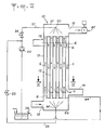
- FIG. 1 a first example of a steam pump, or mass and heat exchanger, according to the invention.
- This steam pump 10 essentially comprises a common vertical enclosure 11 inside which heat exchanges take place between smoke and combustion air.
- a set of vertical tubular walls 12 are arranged inside the enclosure 11 in such a way that, in this example, the external face of the walls of the tubes 12 is in contact with the fumes which are not humidified while the face internal walls of the tubes 12 is in contact with the oxidizing fresh air which circulates in the enclosure 11 inside the tubes 12 and is humidified by means 20, 30 for spraying water or condensates.
- An orifice 15 for introducing fresh air is formed in the enclosure 11 in the vicinity of the bottom 52 thereof and under a lower partition 54 for supporting the tubes 12 and for closing the free spaces between the tubes 12 while an orifice 16 for evacuating heated and humidified air is formed in the enclosure 11 in the vicinity of the upper part 51 thereof and above an upper partition 53 for supporting the tubes 12 and for closing off free spaces between the tubes 12.
- a pipe 13 for supplying hot smoke passes through the enclosure 11 at a level located just below the orifice 16 for evacuating the heated air, and under the partition upper horizontal 53 while a pipe 14 for evacuating cold smoke crosses the enclosure 14 at a level situated just above the orifice 15 for introducing fresh combustion air and above the lower horizontal partition 54
- the fumes symbolized by the arrows 5 thus circulate in the duct 13 for supplying the fumes which is in communication with the passages included in the enclosure 11 between the horizontal partitions 53 and 54 and situated outside the tubes 12, then after having circulated from top to bottom between the partitions 53 and 54, they exit from the steam pump 10 by the outlet pipe 14.
- the air symbolized by arrows 6 circulates against the current with respect to the fumes 5, that is to say from bottom to top.
- the relatively cold and dry fresh air is humidified by a first humidification device 30 disposed at the lower part of the enclosure 11 under the partition 54 and made so as to spray a fine mist into the entire air inlet section inside the tubes 12 at the level of the partition 54, the mist being produced in the same direction as the air flow, this is ie up.
- a second humidification device 20 is disposed at the upper part of the enclosure 11 and is produced so as to spray a fine mist into the entire air outlet section formed by the outlet sections of the tubes 12 passing through the upper partition 53, the fine mist being produced downwards, that is to say against the current with respect to the air flow emerging from the tubes 12.
- the mists produced by the water injection devices 20 and 30 contribute humidify the combustion air and cause water to run off on the internal face of the walls of the tubes 12 which constitute the exchanger proper.
- the air and the water sprayed into the air heat up by contact with the internal faces of the walls of the tubes 12, the external faces of which are in contact with the combustion products. This results in vaporization of the water droplets, the progressive saturation of the air of combustion and condensation in combustion products.
- each tube 12 advantageously have a section of particular shape which improves the efficiency of the exchange. As shown in FIG. 3, each tube 12 can thus have a bean-shaped section with two portions of larger section joined by a narrow connecting portion at the level of which a venturi effect is produced which maintains turbulence at the level of the gas flow circulating inside the tube.
- a groove on the external face of the bean-shaped tubes that is to say on the side of the flue gas circulation, makes it possible to permanently break the film of water formed by the condensates and this prevents them from behaving like an insulating film.
- the condensate film can break naturally due to the fact that a large mass of water collects in the throat and can come off by its own weight.
- the tubes 12 can be metallic, for example stainless steel. However, due to the fact that the exchanger is capable of operating with fumes being at relatively low temperatures, in particular in the case of the association of the steam pump with a direct contact generator, the tubes 12 can be produced in synthetic materials such as PVC or PVDF.
- a boiler for producing hot water or steam necessary for heating or a process and equipped with a forced air burner can be associated with a condenser in which the water in return for use or cold make-up water is used in a first exchange phase to cool the combustion products. Cooling causes the condensation of water vapor from combustion when the inlet temperature of the fluid to be heated is below the dew point of the combustion products.
- the condenser used makes it possible to lower the temperature of the combustion products to a temperature which is of the order of 45 ° C.
- the combustion products already partially cooled and relieved of part of their vapor of water introduced into a steam pump according to the invention will yield a greater or lesser part of the energy which they still contain in the form of recycled energy with the combustion air preheated and humidified by its passage through the pump to steam.
- the steam pump according to the invention allows a reduction in the formation of nitrogen oxide which is often very significant (greater than 50%). This phenomenon is due to the production of a cooler flame due to the "doping" in water vapor of the combustion air and to the concomitant depletion of oxygen in the combustion air.
- An important aspect of the present invention is linked to the spraying of water which is only carried out through the air flow and not through the smoke flow.
- a water tank 23 which can be for example a condensate collector from a condensing generator or a condenser on water associated with a conventional boiler, but could also be a tank of water from an outside source.
- the steam pump according to the invention requires only the use of a relatively small amount of water which can be pumped by a pump 22 at low flow rate which can operate with a low electrical power, for example from the order of a few kilowatts.
- the water pumped by the pump 22 into the reservoir 23 is applied by a line 21 to the upper spray head 20 which is only shown schematically in FIG. 1, but is designed to inject the water in the form of mist in the entire section of the enclosure 11 which is located above the exchanger formed by the tubes 12 and constitutes the outlet section of the heated air intended to be discharged through the outlet orifice 16.
- the second water spray head 30 can be produced in a similar manner to that of the upper head 20 for injecting the water in the form of a mist over the entire section of the enclosure 11 which is located below the exchanger formed from tubes 12 and constitutes the inlet section of the fresh air introduced through the inlet orifice 15.
- Water can be applied to the lower spray head 30 by a pipe 31 supplied by a pump 32 from the water contained in a tank 33.
- the tank 33 can receive by a line 34 condensates collected at the bottom of the tubes 12.
- FIG. 2 shows an alternative embodiment of FIG. 1, in which the upper 20 and lower 30 spray heads, which constitute the means for humidifying the air introduced into the enclosure 11, are supplied using '' a single pump 22 by lines 21 and 26 from the same tank 23 which can be a condensate collector of a condenser as indicated above. Valves 24, 25 are arranged on the pipes 21 and 26 to adjust the water injection rate through the spray heads 20 and 30.
- FIG. 2 which constitutes an embodiment which does not require the using only a single electric pump 22, the condensates formed in the exchanger outside the tubes 12 can be brought back by a pipe 34 to the tank 23.
- FIGs 1 and 2 there is shown an air valve which is disposed in an outlet duct connected to the air outlet orifice 16.
- the valve 40 thus prevents a entrainment of water by capillarity towards the burner and thus prevents the safety members associated with the burner from decommissioning the latter.
- the steam pump according to the invention is particularly suitable for operating in combination with a condensing heat generator, as already indicated above, but can be installed on any thermal equipment by means of a mechanical recovery or ventilation member.
- the steam pump associated with a condensing heat generator can constitute a self-priming device that does not require the addition of fresh water outside at start-up if a condensate recovery and control system is provided.
- a steam pump according to the invention because it leads to the rejection of cold and not very humid fumes, makes it possible to avoid carrying out casing of the chimneys which is always expensive.
- Each water spray head 20, 30 comprises a spray boom 21, 31 provided with a series of nozzles 1 which may have an essentially conical shape and comprise on their large end face 2 a series of small orifices 3 regularly distributed over the whole surface constituting the base of the cone.
- Each nozzle 1 thus ensures the projection, in the form of a fine mist, of fine water droplets 4 throughout the interior volume to a cone whose apex is located at the level of the nozzle 1.
- These nozzles 1 are arranged such so that the conical volumes filled with water droplets 4 overlap.
- Each device 20, 30 thus ensures the projection of a mist into the entire volume delimited by the part of the enclosure 11 in which the inlet orifice 15 resp. Is formed. 16 air outlet and an end plate 53 resp. 54 for supporting the ends of the tubes 12 in which the combustion air circulates.
- the lower head 30 for spraying water situated at the level of the air inlet orifice 15, is arranged so that the water droplets are projected upwards in the direction of air circulation.
- the spraying of water carried out at the lower part of the exchanger causes an oversaturation of the air at the foot of the exchanger and facilitates priming at low temperature.
- the water spraying carried out at the upper part of the exchanger in the vicinity of the air outlet is itself carried out against the current with respect to the air flow.
- the heads 20, 30 for spraying water form a fine mist only in the flow of combustion air and no water droplet is projected into the smoke circulation circuit, which is isolated by partitions 53, 54 and the walls of the tubes 12.
- a steam pump according to the invention can comprise a single stage, as shown in FIGS. 1, 2 and 4, or several similar stages arranged in cascade, as shown in FIG. 6.
- FIG. 6 shows a steam pump comprising two units 10a, 10b which may each be identical to the steam pump of FIG. 4 for example, each with a common enclosure 11 inside which are arranged sets of exchanger tubes 12 , not shown in Figure 6, and water spraying means 20, 30 arranged at the top and bottom of each enclosure 11.
- the orifice 16 for air outlet of the first unit 10a is connected by a pipe 7 to the air inlet port 15 of the second unit 10b.
- the pipe 14 for the smoke outlet from the first unit 10a is connected by a connecting pipe 8 to the pipe 13 for the smoke inlet from the second unit 10b.
- FIG. 6 as in FIGS. 7 and 9, the path of the fumes is symbolized by broken lines 5 while the path of air is symbolized by broken lines 6.
- the operation of the steam pump of FIG. 6 will not be described in more detail since each unit 10a, 10b behaves like the steam pump of FIGS. 1, 2 or 4.
- Figure 7 shows an embodiment quite similar to that of Figure 6, but in which several stages (two stages in the example shown) of exchange are arranged in series in the same enclosure 11.
- these partitions 55, 56 separate two consecutive stages and orifices 14b, 16b are formed in the partitions 55, 56 to constitute zones for the passage of smoke and air between the two successive stages.
- the direction of circulation of the fumes 5 and of the air 6 are reversed in the second stage relative to the first stage, so that for a two-stage steam pump integrated in the same enclosure 11 as shown in FIG. 7, l orifice 16 for evacuating air is located at the bottom of the enclosure 11 while the smoke outlet pipe 14 is located at the top of the enclosure 11.
- a third stage would make it possible to find outlet openings arranged as according to the embodiment of FIG. 4.
- a single spray boom of water 20 can be used at the upper part of the enclosure 11 while two separate water spraying ramps 30a, 30b are arranged at the bottom of the enclosure 11 in two compartments separated by a partition 56.
- Each ramp spraying 20, 30a, 30b can be carried out as described with reference to FIGS. 4 and 5.
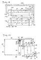
- FIG. 8 represents a second embodiment of a steam pump 110 according to the invention, which differs from the embodiment of FIG. 4 essentially by the horizontal arrangement of the enclosure 111 which has two lateral end faces 151, 152.
- the tubes 112 constituting the actual exchanger between the air and the combustion products can be quite similar to the tubes 12 of FIGS. 1 to 4, but are arranged horizontally between two vertical end plates 153, 154 serving as a support for the tubes 112 relative to the enclosure 111 and for partitions between the air and smoke circuits.
- a fresh air inlet orifice 115 is formed at the upper part of the enclosure 111, in the vicinity of the tube support plate 153 112, and allows the supply of fresh air to the volume comprised between the enclosure 111 and the tubes 153, 154 for supporting the tubes 112, the air 6 circulating, from the left to the right in FIG. 8, around the tubes 112 in the longitudinal direction of the enclosure 111, towards an air outlet orifice 116 located at the lower part of the enclosure 111 in the vicinity of the tube support plate 154.
- a smoke transport pipe 113 opens into a chamber 157 delimited by the lateral end 152 of the enclosure, the tube support plate 154 and part of the enclosure 111, to allow the introduction of the fumes to the inside the tubes 112, one end of which opens into the chamber 157.
- Each of the tubes 112 opens at its end located at the level of the plate 153 in a second lateral chamber 158 delimited by the lateral end 151 of the enclosure, the plate 153 for supporting the tubes and part of the enclosure 111.
- a pipe 114 for evacuating the fumes towards the exterior is in communication with the chamber 158. Contrary to the case of the embodiment of FIGS. 1 to 7 with vertical tubes, in the exchanger of FIG.
- the fumes 5 circulate inside the tubes 112 (from right to left in Figure 8) while the combustion air circulates outside the tubes 112 essentially against the current (i.e. from left to right in the figure 8).
- a vertical enclosure steam pump such as that described with reference to FIGS. 1 to 7, it would also be possible to circulate the fumes inside the tubes 12 and the air in the space outside the tubes 12.
- the ends of the tubes 12 would be closed and the partitions 53, 54 would be perforated and the conduits 13, 14 would be connected by pipes to the ends of each of the tubes 12.
- Such an embodiment is however more complex to be made due to the additional tubing necessary to bring the tubes 12 and the conduits 13, 14 into communication.
- Humidification means 120 constituted by a water spraying boom 121 provided with a set of nozzles 1, is disposed inside the enclosure 111, at the top of the latter and extends over the entire length of the exchanger consisting of the tubes 112, that is to say over the entire length between the support plates 153 and 154.
- the sprayer boom 120 is thus arranged so as to allow the formation of a fine fog not only at the level of the section of the enclosure adjacent to the air inlet orifice 115 and at the level of the section of the enclosure 111 adjacent to the air outlet orifice 116, but also on the entire intermediate zone where the heat exchanges take place through the walls of the tubes 112.
- the spraying of water all along the exchanger contributes to "breaking" the temperature gradients and therefore to maintaining a temperature at little near constant in all the sections of the enclosure from the air inlet 115 to the air outlet 116 while in a steam pump with vertical enclosure such as that of FIG. 4 the exchanges between the air and the fumes through the walls of the tubes 12 cause a change in temperature depending on the sections of the enclosure.
- the water is sprayed using nozzles 1 producing a jet in the form of a full cone, which are similar to the nozzles already described with reference to Figures 4 and 5, and project fine water droplets in conical volumes which overlap so as to create a fine mist throughout space inside the enclosure 111 and external to the tubes 112 in which the combustion air circulates.
- Figure 9 shows the cascade implementation of two units 110a, 110b similar to the unit of Figure 8 to form a two-stage steam pump in series.
- the air outlet port 116a of the first unit 10a is connected by a pipe 107 to the inlet port 115b of air from the second unit 10b and the smoke outlet pipe 114b from the second unit 110b is connected by a connecting pipe 108 to the smoke inlet pipe 113a from the first unit 110a.
- the number of horizontal exchange units 110a, 110b connected in series can naturally be greater than two.
- FIG. 10 shows the application of a steam pump 10 according to the invention not to a condensing boiler or the like, but to a direct contact heat generator.
- FIG. 10 thus shows a heat generator 90 comprising a combustion chamber 94 opening through an opening 95 in an enclosure 91 containing a bath or a zone 93 allowing the heating of a fluid by proceeding by direct contact with the products of combustion 94 through an air inlet orifice 96.
- Combustible fluid such as natural gas
- the enclosure 91 is closed at its upper part by a cover 92 which can be removable.
- the steam products leaving the bath 93 are collected under the cover 92 and evacuated by at least one orifice 97 for evacuating the fumes from the enclosure 91.
- FIG. 10 shows a bath of liquid 93, such as water, which corresponds to the case of submerged combustion, but the invention applies in the same way to the case of a process proceeding by contact.
- a liquid such as a washer-scrubber type device in which a liquid such as water is sprayed in a spray boom arranged in the enclosure at a predetermined level above the bottom of the enclosure 91, the sprayed liquid being brought into direct contact with the combustion products, and the liquid condensates being recovered in the bottom of the enclosure 91.
- FIG 10 there is shown a steam pump 10 according to the invention, which can be in accordance with any of the previously described embodiments and which is connected between the orifice 97 for evacuating the fumes from the enclosure 91 and the combustion air inlet orifice 96 in the combustion chamber 94.
- the steam pump 10 is itself provided with at least one fresh air inlet orifice 6, a orifice 14 for the outlet of the fumes, an orifice 16 for the outlet of humid hot air connected by a pipe 81 to the orifice 96 for the entry of air into the combustion chamber 94 and an orifice 13 for the entry of saturated fumes connected by a pipe 82 to the orifice 97 for evacuating the fumes outside the enclosure 91.
- Figure 10 also shows that it is possible to add to the steam pump 10 pressurizing means located on the side of the combustion products while atmospheric pressure is maintained on the side of the combustion air.
- the pressurizing means may comprise a compressor driven by an electric motor on the air circulating in the pipe 81 connecting the air outlet orifice 16 of the steam pump at the orifice 96 for entry of combustion air into the combustion chamber 94. In this case, however, there is no recovery of expansion energy on the flue gases.
- the pressurizing means comprise a small turbo-compressor 70 which in particular makes it possible to recover the expansion energy at the level of the fumes.
- This turbo-compressor comprises a compressor 71 disposed between the steam pump 10 and the combustion chamber 94 upstream of the orifice 96 for the entry of combustion air into the combustion chamber 94 and a turbine 72 advantageously disposed on the device.
- a motor, or a motor-compressor 73 for starting and making up can also be implemented on the pipe 81 for transferring the combustion air. It will be noted that the expansion compression device 70 can be placed in the vicinity of the combustion chamber 94 and the enclosure 91 or, on the contrary, placed on the pipes 81, 82 in the vicinity of the steam pump 10.
- a superheater 80 on the conduit 81 for transfer of combustion air, which acts on the moist air leaving the steam pump before it enters the compressor 71. If the air is saturated, a minimum overheating of 5 ° C is generally desirable.
- the superheater 80 can be constituted for example by a heat exchanger performing an exchange between the fumes leaving the bath 93 which escape through the orifice 97 of the enclosure 91 and the humid air coming from the steam pump 10 which is transferred via line 81.
Abstract
Description
La présente invention a pour objet une pompe à vapeur d'eau constituée par un échangeur massique et thermique assurant des transferts d'énergie d'une part entre des produits de combustion issus d'un process thermique et ayant traversé un premier condenseur et d'autre part l'air comburant entrant.The present invention relates to a water vapor pump constituted by a mass and heat exchanger ensuring energy transfers on the one hand between combustion products from a thermal process and having passed through a first condenser and on the other hand, the incoming combustion air.
On connait déjà plusieurs types d'échangeurs massiques et thermiques, encore dénommés pompes à vapeur, qui permettent de recycler avec l'air comburant nécessaire à un process thermique une part plus ou moins grande de l'énergie sensible et latente contenue dans les produits de combustion sortant des générateurs à condensation.We already know several types of mass and heat exchangers, also called steam pumps, which make it possible to recycle with the combustion air necessary for a thermal process a greater or lesser part of the sensitive and latent energy contained in the products of combustion coming out of condensing generators.
On a ainsi proposé par le document FR-A-2 446 460 une installation de chauffage à condensation comprenant un échangeur-récupérateur de chaleur pour coupler thermiquement l'air comburant nécessaire au générateur de chaleur avec des produits de combustion issus du générateur de chaleur, des moyens d'humidification étant prévus pour prélever au moins une partie des condensats issus des produits de combustion et pour mettre ces condensats en contact avec l'air comburant. Cet échangeur connu comprend une pluralité de compartiments juxtaposés séparés par des cloisons verticales et communiquant à leurs extrémités avec des chambres inférieure et supérieure, une première série de compartiments alternés étant en communication à une première extrémité avec une première chambre inférieure et à une deuxième extrémité avec une première chambre supérieure tandis que les compartiments immédiatement adjacents aux compartiments alternés de la première série communiquent avec une deuxième chambre supérieure à leur extrémité voisine de ladite première extrémité et avec une deuxième chambre inférieure à leur extrémité voisine de ladite deuxième extrémité. Les compartiments alternés communiquant avec les premières chambres supérieure et inférieure sont parcourus par de l'air à réchauffer tandis que les compartiments alternés communiquant avec les deuxièmes chambres supérieure et inférieure sont parcourus par des produits de combustion. Une première série de rampes d'alimentation en condensats est installée à l'extrémité supérieure des compartiments de la première série tandis qu'une deuxième série de rampes d'alimentation en condensats est installée à l'extrémité supérieure des compartiments de la seconde série. Un tel type d'échangeur massique et thermique s'avère très encombrant, délicat à réaliser et coûteux si l'on souhaite obtenir une efficacité importante. De plus, de par son principe, il assure des échanges à flux croisés et conduit la plupart du temps à une humidification excessive des fumées ou à un phénomène de ruissellement du condensat de part et d'autre des parois de l'échangeur qui provoque souvent une baisse du rendement de l'échange thermique. D'une façon générale, le contrôle des condensats est difficile à effectuer et par ailleurs les installations auxiliaires de pompage ou de ventilation impliquent une consommation d'énergie souvent non négligeable.Document FR-A-2 446 460 has thus proposed a condensation heating installation comprising a heat exchanger-recuperator for thermally coupling the combustion air necessary for the heat generator with combustion products from the heat generator, humidification means being provided for removing at least part of the condensates from the combustion products and for bringing these condensates into contact with the combustion air. This known exchanger comprises a plurality of juxtaposed compartments separated by vertical partitions and communicating at their ends with lower and upper chambers, a first series of alternating compartments being in communication at a first end with a first lower chamber and at a second end with a first upper chamber while the compartments immediately adjacent to the alternating compartments of the first series communicate with a second upper chamber at their end close to said first end and with a second lower chamber at their end close to said second end. The alternating compartments communicating with the first upper and lower chambers are traversed by air to be heated while the alternating compartments communicating with the second upper and lower chambers are traversed by products of combustion. A first series of condensate supply ramps is installed at the upper end of the compartments of the first series while a second series of condensate supply ramps is installed at the upper end of the compartments of the second series. Such a type of mass and heat exchanger proves to be very bulky, difficult to produce and costly if it is desired to obtain high efficiency. In addition, by its principle, it ensures cross-flow exchanges and leads most of the time to excessive humidification of the fumes or to a phenomenon of condensate runoff on either side of the walls of the exchanger which often causes a decrease in the efficiency of the heat exchange. Generally speaking, condensate control is difficult to carry out and, moreover, auxiliary pumping or ventilation installations involve energy consumption which is often not negligible.
On a par ailleurs proposé dans le document FR-A-2 508 616 un dispositif de traitement de gaz relativement chauds et humides, tels que des fumées, et de gaz relativement secs et frais, tels que des gaz comburants d'un foyer, pour récupérer la chaleur et éventuellement les condensats des fumées et réchauffer et humidifier l'air comburant. Ce dispositif de traitement connu met cependant en oeuvre deux enceintes distinctes parcourues l'une par les gaz chauds et humides et l'autre par les gaz relativement secs et frais, chacune des enceintes comportant à sa partie supérieure des moyens de pulvérisation de liquides constitués par les condensats récupérés lors du traitement. Là encore, un tel dispositif de traitement est encombrant du fait de la présence de deux enceintes et est d'une efficacité qui, bien qu'acceptable, reste limitée. Par ailleurs une telle installation implique la mise en oeuvre de moyens d'équilibrage des débits dans les différentes enceintes et des moyens de transfert de fluides (pompes de circulation, ventilateurs) qui peuvent entraîner une consommation d'énergie importante et liée notamment aux pertes de charge d'écoulement des gaz dans les deux enceintes remplies d'un garnissage métallique.Document FR-A-2 508 616 has also proposed a device for treating relatively hot and humid gases, such as fumes, and relatively dry and fresh gases, such as oxidizing gases from a fireplace, for recover the heat and possibly the condensates from the smoke and reheat and humidify the combustion air. This known treatment device however uses two separate enclosures traversed one by hot and humid gases and the other by relatively dry and fresh gases, each of the enclosures comprising at its upper part means for spraying liquids constituted by condensates recovered during treatment. Here again, such a treatment device is bulky due to the presence of two enclosures and is of an efficiency which, although acceptable, remains limited. Furthermore, such an installation involves the use of means for balancing the flow rates in the various enclosures and means for transferring fluids (circulation pumps, fans) which can cause significant energy consumption and linked in particular to losses of gas flow charge in the two chambers filled with a metal lining.
On connaît encore par le document CH-A-148723 une installation de chaudière dans laquelle de l'air comburant sec est préchauffé et de l'eau également préchauffée est injectée dans cet air comburant de manière à obtenir de l'air comburant humidifié dont le niveau de préchauffage est limité.Document CH-A-148723 also discloses a boiler installation in which dry combustion air is preheated and also preheated water is injected into this combustion air so as to obtain humidified combustion air, the preheating level is limited.
Une telle disposition est mise en oeuvre pour empêcher la formation de scories. La vapeur injectée dans l'air comburant est produite à partir d'eau provenant de l'extérieur en prélevant de l'énergie sensible sur les fumées.Such an arrangement is implemented to prevent the formation of slag. The steam injected into the combustion air is produced from water coming from the outside by taking sensitive energy from the fumes.
Les performances énergétiques de la combustion ne sont toutefois pas améliorées puisque l'énergie recyclée se traduit in fine par une production de vapeur d'eau qui n'est pas ensuite condensée et ne peut donc faire l'objet d'une récupération de chaleur latente.The energy performance of combustion is not improved, however, since the recycled energy ultimately results in the production of water vapor which is not then condensed and therefore cannot be the object of latent heat recovery. .
La présente invention vise à remédier aux inconvénients précités et à permettre d'obtenir une efficacité accrue de recyclage de l'enthalpie des produits de combustion avec un échangeur thermique et massique dont la taille ainsi que les coûts de fabrication et d'exploitation sont réduits.The present invention aims to remedy the aforementioned drawbacks and to make it possible to obtain increased efficiency in recycling the enthalpy of the combustion products with a heat and mass exchanger, the size of which as well as the manufacturing and operating costs are reduced.
L'invention a encore pour but de réaliser un échangeur thermique et massique, encore dénommé pompe à vapeur, qui puisse être utilisé en combinaison avec des processus thermiques divers associés ou non à des condenseurs sans qu'il soit nécessaire de procéder à des adaptations délicates, notamment dans le cas de grosses installations, telles que des chaufferies mettant en oeuvre des chaudières à condensation.Another object of the invention is to produce a heat and mass exchanger, also known as a steam pump, which can be used in combination with various thermal processes, whether or not associated with condensers, without the need for delicate adaptations. , in particular in the case of large installations, such as boiler rooms using condensing boilers.
Ces buts sont atteints grâce à une pompe à vapeur d'eau constituée par un échangeur massique et thermique assurant des transferts d'énergie entre d'une part des produits de combustion issus d'un process thermique et ayant traversé un premier condenseur et d'autre part l'air comburant entrant, comprenant une enceinte extérieure, un ensemble de compartiments formant échangeur disposés à l'intérieur de l'enceinte dans le sens longitudinal de celle-ci débouchant à leurs extrémités au niveau d'un premier plan radial et d'un second plan radial, de manière de définir entre lesdits plans radiaux un premier circuit de circulation de fluide gazeux à l'intérieur des compartiments et un second circuit distinct de circulation de fluide gazeux à l'intérieur de l'enceinte mais à l'extérieur des compartiments, un orifice d'introduction d'un premier fluide gazeux à l'intérieur de l'enceinte dans ledit second circuit, un orifice d'évacuation hors de l'enceinte dudit premier fluide gazeux circulant dans ledit second circuit, un orifice d'introduction d'un second fluide gazeux à l'intérieur de l'enceinte dans ledit premier circuit et un orifice d'évacuation hors de l'enceinte dudit second fluide gazeux circulant à contre-courant dans ledit premier circuit, l'un des premier et second fluides gazeux étant constitué par lesdits produits de combustion chauds ayant traversé ledit premier condenseur mais encore chargés d'humidité tandis que l'autre fluide gazeux est constitué par de l'air comburant neuf, des moyens d'humidification de l'air introduit dans l'enceinte, comprenant un ensemble de gicleurs disposés de manière à pulvériser en volume de l'eau en fin brouillard, de telle manière que seules les faces des parois des compartiments en contact avec l'air soient humidifiées, de telle sorte que les compartiments définissent à l'intérieur de l'enceinte un échangeur air-produits de combustion à contre-courant sans fluide intermédiaire dans lequel les transferts d'énergie des produits de combustion vers l'air neuf, des produits de combustion vers l'eau pulvérisée et des condensats des produits de combustion vers l'eau pulvérisée sont effectués à travers la paroi des compartiments tandis que le transfert de l'énergie de l'eau pulvérisée vers l'air est réalisé par contact direct, et les moyens d'humidification d'air étant alimentés en eau à partir d'un réservoir caractérisé en ce que les compartiments sont constitués par des tubes débouchant à leurs extrémités au niveau desdits premier et second plans radiaux dans lesquels sont disposés des moyens assurant le positionnement et le support des tubes par rapport à l'enceinte ainsi que l'obturation des espaces libres de la section de l'enceinte situés à l'extérieur des tubes en ce que les gicleurs sont disposés de manière à pulvériser en volume de l'eau au moins dans toute la section d'entrée du circuit de circulation de l'air et dans toute la section de sortie du circuit de circulation d'air, et en ce que les moyens d'humidification d'air sont alimentés en eau à partir d'un réservoir contenant les condensats issus dudit premier condenseur.These goals are achieved thanks to a water vapor pump constituted by a mass and heat exchanger ensuring energy transfers between on the one hand combustion products from a thermal process and having passed through a first condenser and on the other hand, the incoming combustion air, comprising an external enclosure, a set of compartments forming a heat exchanger arranged inside the enclosure in the longitudinal direction thereof opening at their ends at a first radial plane and d '' a second radial plane, of way of defining between said radial planes a first gaseous fluid circulation circuit inside the compartments and a second separate gaseous fluid circulation circuit inside the enclosure but outside the compartments, an orifice introduction of a first gaseous fluid inside the enclosure into said second circuit, a discharge orifice outside the enclosure of said first gaseous fluid circulating in said second circuit, an orifice for introducing a second gaseous fluid inside the enclosure in said first circuit and a discharge orifice outside the enclosure of said second gaseous fluid flowing against the current in said first circuit, one of the first and second gaseous fluids being constituted by said hot combustion products having passed through said first condenser but still charged with humidity while the other gaseous fluid is constituted by fresh oxidizing air, means of humidifica tion of the air introduced into the enclosure, comprising a set of nozzles arranged so as to spray volume water at the end of the mist, so that only the faces of the walls of the compartments in contact with the air are humidified , so that the compartments define inside the enclosure a counter-current air-combustion products exchanger without intermediate fluid in which the energy transfers from the products of combustion to the fresh air, products of combustion towards the sprayed water and condensates of the combustion products towards the sprayed water are carried through the wall of the compartments while the transfer of energy from the sprayed water to the air is carried out by direct contact, and the air humidification means being supplied with water from a tank characterized in that the compartments are constituted by tubes opening at their ends at the said level s first and second radial planes in which means are arranged ensuring the positioning and the support of the tubes with respect to the enclosure as well as the obturation of the free spaces of the section of the enclosure situated outside the tubes in this that the nozzles are arranged so as to spray volume water at least throughout the inlet section of the air circulation circuit and throughout the outlet section of the air circulation circuit, and in this that the air humidification means are supplied with water to from a tank containing the condensates from said first condenser.
Les tubes présentent des parois lisses et sont avantageusement constitués par des tubes à grande surface d'échange, tels que des tubes à section en forme de "haricot" présentant deux portions de plus grand diamètre mises en communication à l'aide d'une portion étroite de liaison.The tubes have smooth walls and are advantageously constituted by tubes with a large exchange surface, such as tubes in the shape of a "bean" section having two portions of larger diameter placed in communication using a portion close bond.
Compte tenu de l'efficacité des échanges, les tubes de l'échangeur air-produits de combustion peuvent être réalisés en une matière synthétique, telle que le polyfluorure de vinylidène (PVDF) ou le polychlorure de vinyle (PVC) mais peuvent également être métalliques, en acier inoxydable par exemple.Given the efficiency of the exchanges, the tubes of the air-combustion products exchanger can be made of a synthetic material, such as polyvinylidene fluoride (PVDF) or polyvinyl chloride (PVC) but can also be metallic. , in stainless steel for example.
Selon une caractéristique particulière de l'invention, chaque gicleur formant un élément des moyens d'humidification produit un jet sous la forme d'un cône plein, et comprend une multiplicité d'orifices de sortie assurant la pulvérisation d'eau selon un fin brouillard dans tout le volume d'un cône dont le sommet est sensiblement constitué par le sommet du gicleur.According to a particular characteristic of the invention, each nozzle forming an element of the humidification means produces a jet in the form of a solid cone, and comprises a multiplicity of outlet orifices ensuring the spraying of water according to a fine mist. throughout the volume of a cone, the top of which is substantially formed by the top of the nozzle.
Les différents gicleurs sont disposés de manière que les cônes de pulvérisation d'eau se chevauchent.The different nozzles are arranged so that the Water spray cones overlap.
Selon un premier mode de réalisation possible, l'enceinte est disposée verticalement et les moyens d'humidification comprennent un premier ensemble de gicleurs orientés vers le bas et disposés à la partie supérieure de l'enceinte de manière à pulvériser de l'eau sur toute la section de l'enceinte située au-dessus de l'extrémité des tubes constituant l'échangeur air-fumées et un second ensemble de gicleurs orientés vers le haut et disposés à la partie inférieure de l'enceinte de manière à pulvériser de l'eau sur toute la section de l'enceinte située au-dessous des tubes.According to a first possible embodiment, the enclosure is arranged vertically and the humidification means comprise a first set of nozzles oriented downwards and arranged at the upper part of the enclosure so as to spray water over all the section of the enclosure located above the end of the tubes constituting the air-smoke exchanger and a second set of nozzles oriented upwards and arranged at the bottom of the enclosure so as to spray water over the entire section of the enclosure located below the tubes.
Il est ici possible d'utiliser une pompe unique pour alimenter en eau le premier ensemble de gicleurs et le second ensemble de gicleurs à partir d'un réservoir d'eau.It is possible here to use a single pump to supply water to the first set of sprinklers and the second set of sprinklers from a water tank.
Dans le cas d'une enceinte disposée verticalement, de préférence, afin de faciliter la réalisation de la pompe à vapeur, l'air est introduit dans le premier circuit de circulation de fluide gazeux à l'intérieur des tubes et les produits de combustion sont introduits dans le second circuit de circulation de fluide gazeux à l'intérieur de l'enceinte, mais à l'extérieur des tubes.In the case of an enclosure arranged vertically, preferably, in order to facilitate the production of the steam pump, air is introduced into the first gaseous fluid circulation circuit inside the tubes and the combustion products are introduced into the second gaseous fluid circulation circuit inside the enclosure, but outside the tubes.
Selon un autre mode de réalisation de l'invention, l'enceinte est disposée horizontalement et les moyens d'humidification comprennent un ensemble de gicleurs orientés vers le bas et disposés à la partie supérieure de l'enceinte horizontale en étant répartis sur toute la longueur de l'enceinte entre les orifices d'entrée et de sortie d'air.According to another embodiment of the invention, the enclosure is arranged horizontally and the humidification means comprise a set of nozzles oriented downwards and arranged at the upper part of the horizontal enclosure while being distributed over the entire length of the enclosure between the air inlet and outlet ports.
Dans le cas d'une enceinte disposée horizontalement, les produits de combustion sont introduits dans le premier circuit de circulation de fluide gazeux à l'intérieur des tubes et l'air est introduit dans le second circuit de circulation de fluide gazeux à l'intérieur de l'enceinte, mais à l'extérieur des tubes.In the case of an enclosure arranged horizontally, the combustion products are introduced into the first gaseous fluid circulation circuit inside the tubes and air is introduced into the second gaseous fluid circulation circuit inside of the enclosure, but outside the tubes.
La pompe à vapeur selon l'invention est avantageusement utilisée en combinaison avec un processus thermique déjà associé à un condenseur traditionnel et peut constituer ainsi un surcondenseur dans lequel les moyens d'humidification d'air sont alimentés en eau à partir d'un réservoir contenant les condensats issus d'un premier condenseur.The steam pump according to the invention is advantageously used in combination with a thermal process already associated with a traditional condenser and can thus constitute a an over-condenser in which the air humidification means are supplied with water from a tank containing the condensates from a first condenser.
La pompe à vapeur selon l'invention peut être également avantageusement utilisée en combinaison avec un processus ou générateur thermique à contact direct du type laveur scrubber ou combustion submergée, les moyens d'humidification d'air pouvant être alimentés en eau depuis le bloc de récupération de condensat du générateur.The steam pump according to the invention can also be advantageously used in combination with a process or thermal generator with direct contact of the scrubber or submerged combustion type, the air humidification means being able to be supplied with water from the recovery unit. generator condensate.
Selon une caractéristique particulière, la pompe à vapeur comprend en outre un clapet d'air disposé dans un conduit de sortie relié à l'orifice de sortie d'air comburant humide pour empêcher un entraînement d'eau par capillarité vers l'organe de combustion associé audit process thermique.According to a particular characteristic, the steam pump further comprises an air valve disposed in an outlet duct connected to the outlet of the humid combustion air to prevent a entrainment of water by capillarity towards the combustion member. associated with this thermal process.
La pompe à vapeur selon l'invention peut comprendre plusieurs étages montés en cascade et comprenant chacun une enceinte commune avec un échangeur tubulaire air-produits de combustion à contre-courant sans fluide intermédiaire.The steam pump according to the invention can comprise several stages mounted in cascade and each comprising a common enclosure with a tubular air-combustion product of combustion against the current without intermediate fluid.
Toutefois, selon un mode particulier de réalisation, dans le cas d'une pompe à vapeur à enceinte verticale, la pompe à vapeur peut comprendre plusieurs échangeurs tubulaires air-produit de combustion à contre-courant sans fluide intermédiaire disposés à l'intérieur de ladite enceinte commune dans des compartiments séparés par des parois verticales munies d'une première ouverture à l'une de leurs extrémités pour le passage de l'air entre deux compartiments adjacents, et d'une seconde ouverture réalisée au voisinage de l'autre extrémité de l'enceinte pour le passage du flux de produits de combustion dans une paroi verticale de séparation entre compartiments, en maintenant des circuits de circulation distincts à contre-courant pour l'air et les produits de combustion.However, according to a particular embodiment, in the case of a steam pump with a vertical enclosure, the steam pump may comprise several tubular air-product combustion products of countercurrent combustion without intermediate fluid arranged inside said common enclosure in compartments separated by vertical walls provided with a first opening at one of their ends for the passage of air between two adjacent compartments, and a second opening made in the vicinity of the other end of the enclosure for the passage of the flow of combustion products in a vertical partition wall between compartments, maintaining separate circulation circuits against the current for the air and the combustion products.
Selon un aspect particulier de l'invention, la pompe à vapeur peut comprendre en outre un turbo-compresseur comprenant un compresseur situé sur une conduite de transport d'air comburant reliée à l'orifice de sortie d'air saturé et réchauffé et une turbine située sur le conduit de sortie des produits de combustion après passage dans la pompe à vapeur de sorte que les produits de combustion sont maintenus sous pression dans la pompe à vapeur tandis que l'air comburant est maintenu à la pression atmosphérique ambiante lors de son passage dans la pompe à vapeur.According to a particular aspect of the invention, the steam pump can further comprise a turbo-compressor comprising a compressor located on a combustion air transport pipe connected to the outlet outlet for saturated and heated air and a turbine located on the combustion products outlet pipe after passing through the steam pump so that the combustion products are kept under pressure in the steam pump while the combustion air is maintained at ambient atmospheric pressure during its passage in the steam pump.
Dans ce cas, la pompe à vapeur peut encore comprendre un surchauffeur disposé en amont du compresseur sur ladite conduite de transport d'air comburant.In this case, the steam pump may also include a superheater arranged upstream of the compressor on said combustion air transport pipe.
D'autres caractéristiques et avantages de la présente invention ressortiront de la description suivante de modes particuliers de réalisation, donnés à titre d'exemples en référence aux dessins annexés, sur lesquels :
- la figure 1 est une vue schématique en coupe verticale d'une pompe à vapeur selon un premier mode de réalisation de l'invention dans lequel une enceinte unique est placée verticalement,
- la figure 2 est une vue schématique d'une pompe à vapeur semblable à celle de la figure 1, mais dans laquelle les moyens de pulvérisation d'eau sont alimentés à partir d'une source de fluide unique à l'aide d'une pompe unique,
- la figure 3 est une vue en coupe selon la ligne III-III de la figure 1 montrant la forme de la section des tubes constituant l'échangeur de chaleur placé dans l'enceinte de la pompe à vapeur de la figure 1,
- la figure 4 est une vue en coupe axiale des éléments essentiels d'un exemple de pompe à vapeur selon le mode de réalisation des figures 1 et 2,
- la figure 5 est une vue de la face de sortie d'un gicleur utilisé dans les moyens d'humidification installés dans la pompe à vapeur selon l'invention,
- la figure 6 est une vue schématique montrant la mise en oeuvre de deux enceintes verticales d'échange montées en cascade pour constituer une pompe à vapeur selon l'invention,
- la figure 7 est une vue schématique montrant la mise en oeuvre de deux ensembles verticaux d'échange de chaleur séparés par une cloison verticale et montés en série au sein d'une même enceinte dans une pompe à vapeur selon l'invention,
- la figure 8 est une vue en coupe axiale des éléments essentiels d'un exemple de pompe à vapeur selon l'invention avec une enceinte disposée horizontalement,
- la figure 9 est une vue schématique montrant la mise en oeuvre de deux enceintes horizontales d'échange montées en cascade au sein d'une pompe à vapeur selon l'invention, et
- la figure 10 est une vue schématique montrant la mise en oeuvre d'une pompe à vapeur selon l'invention associée à des moyens de mise en pression.
- FIG. 1 is a schematic view in vertical section of a steam pump according to a first embodiment of the invention in which a single enclosure is placed vertically,
- Figure 2 is a schematic view of a steam pump similar to that of Figure 1, but in which the water spray means are supplied from a single fluid source using a pump unique,
- FIG. 3 is a sectional view along line III-III of FIG. 1 showing the shape of the section of the tubes constituting the heat exchanger placed in the enclosure of the steam pump of FIG. 1,
- FIG. 4 is a view in axial section of the essential elements of an example of a steam pump according to the embodiment of FIGS. 1 and 2,
- FIG. 5 is a view of the outlet face of a nozzle used in the humidification means installed in the steam pump according to the invention,
- FIG. 6 is a schematic view showing the implementation of two vertical exchange chambers mounted in cascade to constitute a steam pump according to the invention,
- Figure 7 is a schematic view showing the implementation of two vertical heat exchange assemblies separated by a vertical partition and mounted in series within the same enclosure in a steam pump according to the invention,
- FIG. 8 is a view in axial section of the essential elements of an example of a steam pump according to the invention with an enclosure arranged horizontally,
- FIG. 9 is a schematic view showing the implementation of two horizontal exchange chambers mounted in cascade within a steam pump according to the invention, and
- Figure 10 is a schematic view showing the implementation of a steam pump according to the invention associated with pressurizing means.
On voit sur la figure 1 un premier exemple de pompe à vapeur, ou échangeur massique et thermique, conforme à l'invention.We see in Figure 1 a first example of a steam pump, or mass and heat exchanger, according to the invention.
Cette pompe à vapeur 10 comprend essentiellement une enceinte verticale 11 commune à l'intérieur de laquelle s'effectuent des échanges de chaleur entre fumées et air comburant. Un ensemble de parois tubulaires verticales 12 sont disposées à l'intérieur de l'enceinte 11 de telle manière que, sur cet exemple, la face externe des parois des tubes 12 est en contact avec les fumées qui ne sont pas humidifiées tandis que la face interne des parois des tubes 12 est en contact avec l'air frais comburant qui circule dans l'enceinte 11 à l'intérieur des tubes 12 et est humidifié par des moyens 20, 30 de pulvérisation d'eau ou de condensats.This
Un orifice 15 d'introduction d'air neuf est formé dans l'enceinte 11 au voisinage du fond 52 de celle-ci et sous une cloison inférieure 54 de support des tubes 12 et d'obturation des espaces libres entre les tubes 12 tandis qu'un orifice 16 d'évacuation d'air réchauffé et humidifié est formé dans l'enceinte 11 au voisinage de la partie supérieure 51 de celle-ci et au-dessus d'une cloison supérieure 53 de support de tubes 12 et d'obturation des espaces libres entre les tubes 12.An
Une canalisation 13 d'amenée de fumées chaudes, traverse l'enceinte 11 à un niveau situé juste en dessous de l'orifice 16 d'évacuation de l'air réchauffé, et sous la cloison horizontale supérieure 53 tandis qu'une canalisation 14 d'évacuation de fumées froides traverse l'enceinte 14 à un niveau situé juste au dessus de l'orifice 15 d'introduction d'air comburant neuf et au-dessus de la cloison horizontale inférieure 54. Les fumées symbolisées par les flèches 5 circulent ainsi dans le conduit 13 d'amenée des fumées qui est en communication avec les passages compris dans l'enceinte 11 entre les cloisons horizontales 53 et 54 et situés à l'extérieur des tubes 12, puis après avoir circulé de haut en bas entre les cloisons 53 et 54 sortent de la pompe à vapeur 10 par la canalisation de sortie 14.A
L'air symbolisé par des flèches 6 circule à contre-courant par rapport aux fumées 5, c'est-à-dire de bas en haut. Dès son introduction dans l'enceinte 11 par l'orifice d'entrée 15, l'air neuf relativement froid et sec est humidifié par un premier dispositif d'humidification 30 disposé à la partie inférieure de l'enceinte 11 sous la cloison 54 et réalisé de manière à pulvériser un fin brouillard dans toute la section d'entrée d'air à l'intérieur des tubes 12 au niveau de la cloison 54, le brouillard étant produit dans le même sens que le flux d'air, c'est-à-dire vers le haut.The air symbolized by
Un second dispositif d'humidification 20 est disposé à la partie supérieure de l'enceinte 11 et est réalisé de manière à pulvériser un fin brouillard dans toute la section de sortie d'air constituée par les sections de sortie des tubes 12 traversant la cloison supérieure 53, le fin brouillard étant produit vers le bas, c'est-à-dire à contre-courant par rapport au flux d'air débouchant des tubes 12. Les brouillards produits par les dispositifs d'injection d'eau 20 et 30 contribuent à humidifier l'air comburant et provoquent un ruissellement de l'eau sur la face interne des parois des tubes 12 qui constituent l'échangeur proprement dit. L'air et l'eau pulvérisée dans l'air se réchauffent par contact avec les faces internes des parois des tubes 12, dont les faces externes sont en contact avec les produits de combustion. Il s'ensuit une vaporisation des gouttelettes d'eau, la saturation progressive de l'air de combustion et la condensation dans les produits de combustion.A
Les tubes 12 présentent avantageusement une section de forme particulière qui améliore l'efficacité de l'échange. Comme cela est représenté sur la figure 3, chaque tube 12 peut ainsi présenter une section en forme de haricot avec deux portions de plus grande section réunies par une portion étroite de liaison au niveau de laquelle est produit un effet venturi qui entretient des turbulences au niveau du flux gazeux circulant à l'intérieur du tube. De plus, la présence d'une gorge sur la face externe des tubes en forme de haricot, c'est-à-dire du côté de la circulation des fumées, permet de casser en permanence le film d'eau formé par les condensats et évite ainsi que ces derniers se comportent comme un film isolant. Le film de condensat peut se briser naturellement du fait qu'une masse importante d'eau s'accumule dans la gorge et peut se décrocher par son propre poids.The
Les tubes 12 peuvent être métalliques par exemple en acier inoxydable. Toutefois, du fait que l'échangeur est capable de fonctionner avec des fumées se trouvant à de relativement faibles températures, notamment dans le cas de l'association de la pompe à vapeur avec un générateur à contact direct les tubes 12 peuvent être réalisés en des matières synthétiques telles que le PVC ou le PVDF.The
A titre d'exemple, une chaudière de production d'eau chaude ou de vapeur nécessaire à un chauffage ou à un process et équipée d'un brûleur à air soufflé peut être associée à un condenseur dans lequel les eaux en retour d'utilisation ou de l'eau froide d'appoint sont utilisées dans une première phase d'échange pour refroidir les produits de combustion. Le refroidissement provoque la condensation de la vapeur d'eau issue de la combustion lorsque la température d'entrée du fluide à chauffer est en dessous de la température de rosée des produits de combustion. Si le condenseur utilisé permet d'abaisser la température des produits de combustion jusqu'à une température qui est de l'ordre de 45°C, les produits de combustion déjà partiellement refroidis et délestés d'une partie de leur vapeur d'eau introduits dans une pompe à vapeur selon l'invention cèderont une part plus ou moins grande de l'énergie qu'ils contiennent encore sous forme d'énergie recyclée avec l'air comburant préchauffé et humidifié par son passage dans la pompe à vapeur.For example, a boiler for producing hot water or steam necessary for heating or a process and equipped with a forced air burner can be associated with a condenser in which the water in return for use or cold make-up water is used in a first exchange phase to cool the combustion products. Cooling causes the condensation of water vapor from combustion when the inlet temperature of the fluid to be heated is below the dew point of the combustion products. If the condenser used makes it possible to lower the temperature of the combustion products to a temperature which is of the order of 45 ° C., the combustion products already partially cooled and relieved of part of their vapor of water introduced into a steam pump according to the invention will yield a greater or lesser part of the energy which they still contain in the form of recycled energy with the combustion air preheated and humidified by its passage through the pump to steam.
Dans la pompe à vapeur selon l'invention qui possède une surface d'échange constituée par les tubes 12 et est équipée de deux têtes 20, 30 de pulvérisation de condensats, on observe que de l'air comburant pris à 10°C avec une humdité relative de 60% est porté à 42°C avec une humidité relative de 95%. Dans le même temps les fumées qui étaient à 45°C en sortie de condenseur seront rejetées saturées à 25°C.In the steam pump according to the invention which has an exchange surface constituted by the
Par ailleurs, outre les économies importantes qu'elle génère, la pompe à vapeur selon l'invention permet une réduction de la formation d'oxyde d'azote souvent très importante (supérieure à 50%). Ce phénomène est dû à l'obtention d'une flamme plus froide en raison du "dopage" en vapeur d'eau de l'air comburant et à la raréfaction concomitante de l'oxygène dans l'air comburant.Furthermore, in addition to the significant savings it generates, the steam pump according to the invention allows a reduction in the formation of nitrogen oxide which is often very significant (greater than 50%). This phenomenon is due to the production of a cooler flame due to the "doping" in water vapor of the combustion air and to the concomitant depletion of oxygen in the combustion air.
Dans la pompe à vapeur selon l'invention, grâce à l'utilisation de tubes 12 dont une face n'est en contact qu'avec les fumées tandis que l'autre face est en contact avec l'air et l'eau pulvérisée, les transferts d'énergie simultanés entre les produits de combustion et l'air comburant sont effectués sous les quatre formes suivantes :
- transfert de l'énergie des fumées vers l'air par voie sèche à travers la paroi des
tubes 12, - transfert de l'énergie des fumées vers l'eau pulvérisée par voie sèche à travers la paroi des
tubes 12, - transfert de l'énergie des condensats de fumées vers l'eau pulvérisée par voie sèche à travers la paroi des
tubes 12, - transfert de l'énergie de l'eau pulvérisée vers l'air par voie directe au sein du circuit de circulation de l'air.
- transfer of the energy from the flue gases to the air by dry route through the wall of the
tubes 12, - transfer of the energy from the smoke to the water sprayed dry via the wall of the
tubes 12, - transfer of the energy from the smoke condensates to the water sprayed dry through the wall of the
tubes 12, - transfer of energy from the sprayed water to the air by direct route within the air circulation circuit.
Un aspect important de la présente invention est lié à la pulvérisation d'eau qui n'est effectuée qu'à travers le flux d'air et non à travers le flux de fumées.An important aspect of the present invention is linked to the spraying of water which is only carried out through the air flow and not through the smoke flow.
Sur la figure 1 on a représenté un réservoir d'eau 23 qui peut être par exemple un collecteur de condensats issus d'un générateur à condensation ou d'un condenseur sur l'eau associé à une chaudière classique, mais pourrait également être un réservoir d'eau provenant d'une source extérieure. D'une façon générale, la pompe à vapeur selon l'invention ne nécessite que l'utilisation d'une relativement faible quantité d'eau qui peut être pompée par une pompe 22 à faible débit pouvant fonctionner avec une faible puissance électrique par exemple de l'ordre de quelques kilowatts. L'eau pompée par la pompe 22 dans le réservoir 23 est appliquée par une conduite 21 à la tête de pulvérisation supérieure 20 qui n'est représentée que de façon schématique sur la figure 1, mais est conçue pour injecter l'eau sous forme de brouillard dans toute la section de l'enceinte 11 qui est située au-dessus de l'échangeur formé des tubes 12 et constitue la section de sortie de l'air réchauffé destiné à être évacué par l'orifice de sortie 16.In Figure 1 there is shown a
La seconde tête 30 de pulvérisation d'eau peut être réalisée d'une façon semblable à celle de la tête supérieure 20 pour injecter l'eau sous forme de brouillard sur toute la section de l'enceinte 11 qui est située au-dessous de l'échangeur formé des tubes 12 et constitue la section d'entrée de l'air neuf introduit par l'orifice d'entrée 15. L'eau peut être appliquée à la tête de pulvérisation inférieure 30 par une canalisation 31 alimentée par une pompe 32 à partir de l'eau contenue dans un réservoir 33. Le réservoir 33 peut recevoir par une ligne 34 des condensats recueillis à la partie inférieure des tubes 12.The second
La figure 2 montre une variante de réalisation de la figure 1, dans laquelle les têtes de pulvérisation supérieure 20 et inférieure 30, qui constituent les moyens d'humidification de l'air introduit dans l'enceinte 11, sont alimentées à l'aide d'une seule pompe 22 par des lignes 21 et 26 à partir d'un même réservoir 23 qui peut être un collecteur des condensats d'un condenseur comme indiqué plus haut. Des vannes 24, 25 sont disposées sur les canalisations 21 et 26 pour régler le débit d'injection d'eau à travers les têtes de pulvérisation 20 et 30. Dans le cas de la figure 2, qui constitue un mode de réalisation ne nécessitant la mise en oeuvre que d'une seule pompe électrique 22, les condensats formés dans l'échangeur à l'extérieur des tubes 12 peuvent être ramenés par une canalisation 34 vers le réservoir 23.FIG. 2 shows an alternative embodiment of FIG. 1, in which the upper 20 and lower 30 spray heads, which constitute the means for humidifying the air introduced into the
Sur les figures 1 et 2, on a représenté un clapet d'air qui est disposé dans un conduit de sortie relié à l'orifice 16 de sortie d'air. Le clapet 40 empêche ainsi un entraînement d'eau par capillarité vers le brûleur et évite ainsi que les organes de sécurité associés au brûleur ne procèdent à une mise hors service de celui-ci.In Figures 1 and 2, there is shown an air valve which is disposed in an outlet duct connected to the
La pompe à vapeur selon l'invention est particulièrement adaptée pour fonctionner en combinaison avec un générateur de chaleur à condensation, comme déjà indiqué plus haut, mais peut être installée sur tout équipement thermique grâce à un organe de reprise ou de ventilation mécanique.The steam pump according to the invention is particularly suitable for operating in combination with a condensing heat generator, as already indicated above, but can be installed on any thermal equipment by means of a mechanical recovery or ventilation member.
Lorsque la pompe à vapeur est installée en dérivation au conduit de fumées d'un équipement thermique, les débits des flux d'air et de fumées sont équilibrés par la mise en place d'un variateur de vitesse ou d'un système équivalent sur l'organe de reprise.When the steam pump is installed as a bypass to the flue pipe of thermal equipment, the flow rates of the air and smoke flows are balanced by the installation of a variable speed drive or an equivalent system on the 'recovery organ.
On notera que la pompe à vapeur associée à un générateur de chaleur à condensation peut constituer un dispositif auto-amorçant ne nécessitant pas d'apport d'eau neuve extérieure au démarrage s'il est prévu un système de récupération et de contrôle de condensats.It will be noted that the steam pump associated with a condensing heat generator can constitute a self-priming device that does not require the addition of fresh water outside at start-up if a condensate recovery and control system is provided.
Par ailleurs, une pompe à vapeur selon l'invention, du fait qu'elle conduit au rejet de fumées froides et peu humides, permet d'éviter de procéder à un tubage des cheminées qui est toujours coûteux.Furthermore, a steam pump according to the invention, because it leads to the rejection of cold and not very humid fumes, makes it possible to avoid carrying out casing of the chimneys which is always expensive.
On décrira maintenant de façon plus détaillée en référence aux figures 4 et 5 les moyens de pulvérisation d'eau 20, 30 utilisés dans une pompe à vapeur à enceinte verticale telle que la pompe à vapeur déjà décrite en référence aux figures 1 à 3.A more detailed description will now be given with reference to FIGS. 4 and 5 of the water spraying means 20, 30 used in a steam pump with a vertical enclosure such as the steam pump already described with reference to Figures 1 to 3.
Chaque tête de pulvérisation d'eau 20, 30 comprend une rampe de pulvérisation 21, 31 munie d'une série de gicleurs 1 qui peuvent présenter une forme essentiellement conique et comportent sur leur grande face terminale 2 une série de petits orifices 3 régulièrement répartis sur toute la surface constituant la base du cône. Chaque gicleur 1 assure ainsi la projection, sous la forme d'un fin brouillard, de fines gouttelettes d'eau 4 dans tout le volume intérieur à un cône dont le sommet est situé au niveau du gicleur 1. Ces gicleurs 1 sont disposés de telle manière que les volumes coniques remplis de gouttelettes d'eau 4 se chevauchent. Chaque dispositif 20, 30 assure ainsi la projection d'un brouillard dans tout le volume délimité par la partie de l'enceinte 11 dans laquelle est formé l'orifice d'entrée 15 resp. de sortie 16 d'air et une plaque terminale 53 resp. 54 de support des extrémités des tubes 12 dans lesquels circule l'air comburant.Each
La mise en oeuvre de moyens de pulvérisation qui, grâce à leur configuration et à la pression appliquée aux gicleurs, permettent de créer un fin brouillard, est essentielle pour éviter que se forme trop rapidement le long de la paroi des tubes 12 un voile d'eau qui constituerait un isolant thermique.The use of spraying means which, by virtue of their configuration and the pressure applied to the nozzles, make it possible to create a fine mist, is essential in order to prevent the formation of a haze too quickly along the wall of the tubes. water which would constitute a thermal insulator.
La tête inférieure 30 de pulvérisation d'eau, située au niveau de l'orifice d'entrée d'air 15, est disposée de manière que les gouttelettes d'eau soient projetées vers le haut dans le sens de circulation de l'air. La pulvérisation d'eau réalisée à la partie inférieure de l'échangeur provoque une sursaturation de l'air au pied de l'échangeur et facilite l'amorçage à basse température. La pulvérisation d'eau réalisée à la partie supérieure de l'échangeur au voisinage de la sortie de l'air est elle-même effectuée à contre-courant par rapport au flux de circulation d'air.The
Dans tous les cas, les têtes 20, 30 de pulvériation d'eau ne forment un fin brouillard que dans le flux d'air comburant et aucune gouttelette d'eau n'est projetée dans le circuit de circulation des fumées, qui est isolé par les cloisons 53, 54 et les parois des tubes 12.In all cases, the
Une pompe à vapeur selon l'invention peut comprendre un seul étage, comme représenté sur les figures 1, 2 et 4, ou plusieurs étages semblables disposés en cascade, comme représenté sur la figure 6.A steam pump according to the invention can comprise a single stage, as shown in FIGS. 1, 2 and 4, or several similar stages arranged in cascade, as shown in FIG. 6.
La figure 6 montre une pompe à vapeur comprenant deux unités 10a, 10b pouvant être chacune identique à la pompe à vapeur de la figure 4 par exemple, avec chacune une enceinte commune 11 à l'intérieur de laquelle sont disposés des ensembles de tubes échangeurs 12, non représentés sur la figure 6, et des moyens de pulvérisation d'eau 20, 30 disposés en haut et en bas de chaque enceinte 11. L'orifice 16 de sortie d'air de la première unité 10a est reliée par une conduite 7 à l'orifice d'entrée d'air 15 de la seconde unité 10b. De même la canalisation 14 de sortie des fumées de la première unité 10a est reliée par une conduite de liaison 8 à la canalisation 13 d'entrée de fumées de la seconde unité 10b. Sur la figure 6, de même que sur les figures 7 et 9, le trajet des fumées est symbolisé par des traits discontinus 5 tandis que le trajet de l'air est symbolisé par des traits discontinus 6. Le fonctionnement de la pompe à vapeur de la figure 6 ne sera pas décrit de façon plus détailée puisque chaque unité 10a, 10b se comporte comme la pompe à vapeur des figures 1, 2 ou 4.FIG. 6 shows a steam pump comprising two
La figure 7 montre un mode de réalisation assez semblable à celui de la figure 6, mais dans lequel plusieurs étages (deux étages dans l'exemple représenté) d'échange sont disposés en série dans la même enceinte 11. Dans ce cas, ces cloisons 55, 56 séparent deux étages consécutifs et des orifices 14b, 16b sont formés dans les cloisons 55, 56 pour constituer des zones de passage de fumées et d'air entre les deux étages successifs. Le sens de circulation des fumées 5 et de l'air 6 sont inversés dans le deuxième étage par rapport au premier étage, de sorte que pour une pompe à vapeur à deux étages intégrés dans une même enceinte 11 comme représenté sur la figure 7, l'orifice 16 d'évacuation d'air se trouve situé au bas de l'enceinte 11 tandis que la canalisation de sortie des fumées 14 est située en haut de l'enceinte 11. La mise en oeuvre d'un troisième étage permettrait de retrouver des orifices de sortie disposés comme selon le mode de réalisation de la figure 4. Compte tenu des sens de circulation du flux d'air 6 adopté dans le mode de réalisation de la figure 7, une rampe unique de pulvérisation d'eau 20 peut être utilisée à la partie supérieure de l'enceinte 11 tandis que deux rampes de pulvérisation d'eau 30a, 30b distinctes sont disposées dans le bas de l'enceinte 11 dans deux compartiments séparés par une cloison 56. Chaque rampe de pulvérisation 20, 30a, 30b peut être réalisée de la façon décrite en référence aux figures 4 et 5.Figure 7 shows an embodiment quite similar to that of Figure 6, but in which several stages (two stages in the example shown) of exchange are arranged in series in the
La figure 8 représente un second mode de réalisation d'une pompe à vapeur 110 selon l'invention, qui se distingue du mode de réalisation de la figure 4 essentiellement par la disposition horizontale de l'enceinte 111 qui présente deux faces d'extrémité latérales 151, 152. Les tubes 112 constituant l'échangeur proprement dit entre l'air et les produits de combustion peuvent être tout à fait analogues aux tubes 12 des figures 1 à 4, mais sont disposés horizontalement entre deux plaques d'extrémité verticales 153, 154 servant de support des tubes 112 par rapport à l'enceinte 111 et de cloisons de séparation entre les circuits d'air et de fumées. Un orifice d'entrée d'air neuf 115 est formé à la partie supérieure de l'enceinte 111, au voisinage la plaque 153 de support de tubes 112, et permet l'alimentation en air frais du volume compris entre l'enceinte 111 et les plaques 153, 154 de support des tubes 112, l'air 6 circulant, de la gauche vers la droite sur la figure 8, autour des tubes 112 dans le sens longitudinal de l'enceinte 111, vers un orifice de sortie d'air 116 situé à la partie inférieure de l'enceinte 111 au voisinage de la plaque 154 de support de tubes. Une canalisation de transport de fumées 113 débouche dans une chambre 157 délimitée par l'extrémité latérale 152 de l'enceinte, la plaque 154 de support de tubes et une partie de l'enceinte 111, pour permettre l'introduction des fumées à l'intérieur des tubes 112 dont une extrémité débouche dans la chambre 157. Chacun des tubes 112 débouche par son extrémité située au niveau de la plaque 153 dans une seconde chambre latérale 158 délimitée par l'extrémité latérale 151 de l'enceinte, la plaque 153 de support des tubes et une partie de l'enceinte 111. Une canalisation 114 d'évacuation des fumées vers l'extérieur est en communication avec la chambre 158. Contrairement au cas du mode de réalisation des figures 1 à 7 à tubes verticaux, dans l'échangeur de la figure 8 défini par les tubes 112, les fumées 5 circulent à l'intérieur des tubes 112 (de la droite vers la gauche sur la figure 8) tandis que l'air comburant circule à l'extérieur des tubes 112 essentiellement à contre-courant (c'est-à-dire de la gauche vers la droite sur la figure 8). On notera que dans une pompe à vapeur à enceinte verticale, telle que celle décrite en référence aux figures 1 à 7, il serait également possible de faire circuler les fumées à l'intérieur des tubes 12 et l'air dans l'espace extérieur aux tubes 12. Dans ce cas, les extrémités des tubes 12 seraient obturées et les cloisons 53, 54 seraient ajourées et les conduites 13, 14 seraient reliées par des tubulures aux extrémités de chacun des tubes 12. Un tel mode de réalisation est toutefois plus complexe à réaliser du fait des tubulures additionnelles nécessaires pour mettre en communication les tubes 12 et les conduits 13, 14.FIG. 8 represents a second embodiment of a
Des moyens d'humidification 120 constitués par une rampe de pulvérisation d'eau 121 munie d'un ensemble de gicleurs 1, est disposée à l'intérieur de l'enceinte 111, à la partie supérieure de celle-ci et s'étend sur toute la longueur de l'échangeur constitué des tubes 112 c'est-à-dire sur toute la longueur comprise entre les plaques de support 153 et 154. La rampe de pulvérisation 120 est ainsi disposée de manière à permettre la formation d'un fin brouillard non seulement au niveau de la section de l'enceinte voisine de l'orifice d'entrée d'air 115 et au niveau de la section de l'enceinte 111 voisine de l'orifice de sortie d'air 116, mais également sur toute la zone intermédiaire où s'effectuent les échanges de chaleur à travers les parois des tubes 112. La pulvérisation d'eau tout le long de l'échangeur contribue à "casser" les gradients de température et donc à maintenir une température à peu près constante dans toutes les sections de l'enceinte depuis l'entrée d'air 115 jusqu'à la sortie d'air 116 alors que dans une pompe à vapeur à enceinte verticale telle que celle de la figure 4 les échanges entre l'air et les fumées à travers les parois des tubes 12 provoquent une évolution de la température selon les sections de l'enceinte.Humidification means 120 constituted by a
En tout état de cause, comme dans le cas d'une pompe à vapeur selon les figures 1 à 4, dans le mode de réalisation de la figure 8, la pulvérisation de l'eau est réalisée à l'aide de gicleurs 1 produisant un jet sous la forme d'un cône plein, qui sont semblables aux gicleurs déjà décrits en référence aux figures 4 et 5, et projettent de fines gouttelettes d'eau dans des volumes coniques qui se chevauchent de façon à créer un fin brouillard dans tout l'espace interne à l'enceinte 111 et externe aux tubes 112 dans lequel circule l'air comburant.In any event, as in the case of a steam pump according to FIGS. 1 to 4, in the embodiment of FIG. 8, the water is sprayed using
La figure 9 montre la mise en oeuvre en cascade de deux unités 110a, 110b semblables à l'unité de la figure 8 pour constituer une pompe à vapeur à deux étages en série. Dans ce cas, et d'une façon similaire au mode de réalisation de la figure 6, l'orifice 116a de sortie de l'air de la première unité 10a est relié par une conduite 107 à l'orifice 115b d'entrée d'air de la deuxième unité 10b et la canalisation 114b de sortie des fumées de la seconde unité 110b est reliée par une canalisation de liaison 108 à la canalisation 113a d'entrée des fumées de la première unité 110a. Le nombre d'unités horizontales d'échange 110a, 110b montées en série peut naturellement être supérieur à deux.Figure 9 shows the cascade implementation of two
La figure 10 montre l'application d'une pompe à vapeur 10 selon l'invention non pas à une chaudière à condensation ou similaire, mais à un générateur de chaleur à contact direct.FIG. 10 shows the application of a
On voit ainsi sur la figure 10 un générateur de chaleur 90 comprenant une chambre de combustion 94 débouchant par une ouverture 95 dans une enceinte 91 contenant un bain ou une zone 93 permettant le chauffage d'un fluide en procédant par contact direct avec les produits de combustion 94 par un orifice 96 d'entrée d'air. Le fluide combustible, tel que du gaz naturel, est introduit dans la chambre de combustion 94 par un dispositif d'injection classique, qui n'est pas représenté. L'enceinte 91 est fermée à sa partie supérieure par un couvercle 92 qui peut être amovible. Les produits vapeur sortant du bain 93 sont collectés sous le couvercle 92 et évacués par au moins un orifice 97 d'évacuation des fumées hors de l'enceinte 91.FIG. 10 thus shows a
On a représenté sur la figure 10 un bain de liquide 93, tel que de l'eau, qui correspond au cas d'une combustion submergée, mais l'invention s'applique de la même manière au cas d'un process procédant par contact direct entre des produits de combustion et un liquide, tel qu'un dispositif du type laveur-scrubber dans lequel un liquide tel que de l'eau est pulvérisé dans une rampe de pulvérisation disposée dans l'enceinte à un niveau prédéterminé au-dessus du fond de l'enceinte 91, le liquide pulvérisé étant mis en contact direct avec les produits de combustion, et les condensats liquides étant récupérés dans le fond de l'enceinte 91.FIG. 10 shows a bath of
Sur la figure 10, on a représenté une pompe à vapeur 10 selon l'invention, qui peut être conforme à l'un quelconque des modes de réalisation précédemment décrits et qui est connectée entre l'orifice 97 d'évacuation des fumées hors de l'enceinte 91 et l'orifice 96 d'entrée d'air comburant dans la chambre de combustion 94. La pompe à vapeur 10 est elle-même munie d'au moins un orifice d'entrée d'air frais 6, d'un orifice 14 de sortie des fumées, d'un orifice 16 de sortie d'air chaud humide connecté par une conduite 81 à l'orifice 96 d'entrée d'air dans la chambre de combustion 94 et d'un orifice 13 d'entrée de fumées saturées connecté par une conduite 82 à l'orifice 97 d'évacuation des fumées hors de l'enceinte 91.In Figure 10, there is shown a
La figure 10 montre par ailleurs qu'il est possible d'adjoindre à la pompe à vapeur 10 des moyens de mise en pression situés du côté des produits de combustion tandis que la pression atmosphérique est maintenue du côté de l'air comburant.Figure 10 also shows that it is possible to add to the
Les moyens de mise en pression peuvent comprendre un compresseur entraîné par un moteur électrique sur l'air circulant dans la conduite 81 reliant l'orifice 16 de sortie d'air de la pompe à vapeur à l'orifice 96 d'entrée d'air comburant dans la chambre de combustion 94. Dans ce cas, il n'existe cependant pas de récupération d'énergie de détente sur les fumées. Aussi, de préférence, les moyens de mise en pression comprennent un petit turbo-compresseur 70 qui permet notamment de récupérer l'énergie de détente au niveau des fumées. Ce turbo-compresseur comprend un compresseur 71 disposé entre la pompe à vapeur 10 et la chambre de combustion 94 en amont de l'orifice 96 d'entrée d'air comburant dans la chambre de combustion 94 et une turbine 72 disposée avantageusement sur le dispositif 14 d'évacuation des fumées 5 en sortie de la pompe à vapeur 10. Un moteur, ou un moto-compresseur 73 de démarrage et d'appoint peut être également mis en oeuvre sur la conduite 81 de transfert de l'air comburant. On notera que le dispositif de compression détente 70 peut être placé au voisinage de la chambre de combustion 94 et de l'enceinte 91 ou au contraire placé sur les conduites 81, 82 au voisinage de la pompe à vapeur 10.The pressurizing means may comprise a compressor driven by an electric motor on the air circulating in the
A titre d'option, il est possible d'installer sur la conduite 81 de transfert d'air comburant un surchauffeur 80 qui agit sur l'air humide sortant de la pompe à vapeur avant son entrée dans le compresseur 71. Si l'air est saturé, une surchauffe minimale de 5°C est en général souhaitable. Le surchauffeur 80 peut être constitué par exemple par un échangeur de chaleur réalisant un échange entre les fumées en sortie du bain 93 qui s'échappent par l'orifice 97 de l'enceinte 91 et l'air humide issu de la pompe à vapeur 10 qui est transféré par la conduite 81.As an option, it is possible to install a
Claims (16)
- Vapor pump constituted by a mass and heat exchanger providing energy and mass transfers between on the one hand combustion products from a thermal process which have gone through a first condenser and on the other hand the inlet combustion air, comprising an outer enclosure (11; 111) a set of tubes constituting an exchanger disposed lengthwise inside the enclosure (11; 111) and opening out at their ends in first and second radial planes (53, 54; 153, 154) thereby defining between said radial planes a first gaseous fluid flow circuit inside the tubes and a distinct second gaseous fluid flow circuit inside the enclosure (11; 111) but outside the tubes, an inlet orifice (13; 115) for admitting a first gaseous fluid into the enclosure (11; 111) in said second circuit, an outlet orifice (14; 116) for exhausting from the enclosure said first gaseous fluid flowing in said second circuit, an inlet orifice (15; 113) for admitting a second gaseous fluid into the enclosure into said first circuit, and an outlet (16; 114) orifice for exhausting from said enclosure evacuating said second gaseous fluid flowing as a counterflow in said first circuit, one of said first and second gaseous fluids being constituted by said hot moist combustion products which have gone through said first condenser but are still filled with moisture while the other gaseous fluid is constituted by new combustion air, humidifier means (20, 30; 120) for moistening the air admitted into the enclosure (11; 111), which comprise a set of nozzles (1) disposed so as to spray a volume of a fine mist of water in such a way that only those faces of the walls of the tubes that are in contact with the air are moistened, so that the tubes define a counterflow exchanger between the air and the combustion products inside the enclosure (11; 111) without using an intermediate fluid and in which energy is transferred from the combustion products to the new air, from the combustion products to the sprayed water, and from the condensates of the combustion products to the sprayed water are effected via the walls of the tubes while the transfer of energy from the sprayed water is achieved by direct contact, and the humidifier means for moistening the air (20, 30; 120) being supplied with water from a tank (23), characterized in that the compartments are constituted by tubes (12, 112) issuing at their ends at the level of said first and second radial planes (53, 54; 153, 154) in which means are provided to ensure the positioning and support of the tubes (12; 112) with respect to the enclosure (11; 111) as well as the obturation of the free spaces of the cross-section of the enclosure 11; 111) situated outside the tubes (12; 112), in that the nozzles are so placed as to be able to spray volumes of water at least throughout the inlet cross-section of the air-flowing circuit and through the whole outlet section of the air circulation circuit, and in that the air moistening means are fed with water from a tank containing the condensates produced by the first condenser.
- Vapor pump according to claim 1, characterized in that the tubes (12 ; 112) have smooth walls.
- Vapor pump according to claim 1 or claim 2, characterized in that the tubes (12; 112) are constituted by tubes having a large heat exchange area, such as tubes of kidney-shaped cross-section, having two larger diameter portions put into communication via a narrow connecting portion.
- Vapor pump according to any one of claims 1 to 3, characterized in that the tubes (12; 112)of the heat exchanger for exchanging heat between the combustion products and the air are made of a synthetic material such as polyvinylidene fluoride or polyvinyl chloride.
- Vapor pump according to any one of claims 1 to 4, characterized in that each nozzle (1) constituting a component of the humidifier means (20, 30; 120) produces a jet in the form of a solid cone and comprises a multiplicity of outlet orifices for spraying water in a fine mist throughout the volume of a cone (4) whose apex is substantially constituted by the apex of the nozzle (1).
- Vapor pump according to claim 5, characterized in that the various nozzles (1) are disposed so that the water spray cones (4) overlap.
- Vapor pump according to any one of claims 1 to 6, characterized in that the enclosure (11) is disposed vertically and in that the humidifier means (20, 30) comprise a first set (20) of nozzles (1) directed downwards and disposed in the top portion of the enclosure (11) so as to spray water over the entire section of the enclosure situated above the ends of the tubes (12) constituting the air and flue gas heat exchanger, and a second set (30) of nozzles (1) directed upwards and disposed at the bottom of the enclosure (11) so as to spray water over the entire section of the enclosure situated beneath the tubes (12).
- Vapor pump according to claim 7, characterized in that the air is inserted into the first gaseous fluid flow circuit inside the tubes (12) and the combustion products are inserted into the second gaseous fluid flow circuit inside the enclosure, but outside the tubes (12).
- Vapor pump according to claim 7 or claim 8, characterized in that it comprises a single pump (22) for feeding both the first set (20) of nozzles (1) and the second set (30) of nozzles (1) from a single water tank (23).
- Vapor pump according to any one of claims 1 to 6, characterized in that the enclosure (111) is disposed horizontally, and in that the humidifier means (120) comprise a set of nozzles (1) directed downwards and disposed in the top of the horizontal enclosure (111) being distributed over the entire length of the enclosure (111) between the air inlet and outlet orifices (115, 116).
- Vapor pump according to claim 10, characterized in that the combustion products are inserted into the first gaseous fluid flow circuit inside the tubes (112) and the air is inserted into the second gaseous fluid flow circuit inside the enclosure, but outside the tubes (112).
- Vapor pump according to any one of claims 1 to 11, characterized in that it further comprises an air valve (40) disposed in an outlet duct connected to the moist combustion air outlet orifice (16) in order to prevent water being driven by capillarity to the combustion member associated with said thermal process.
- Vapor pump according to any one of claims 1 to 12, characterized in that it comprises a plurality of stages connected in cascade each comprising a common enclosure (11; 111) with a set of counterflow tubes for heat exchange between the air and the combustion products without using an intermediate fluid.
- Vapor pump according to any one of claims 7 to 9, characterized in that it comprises a plurality of sets of counterflow tubes for heat exchange between the air and the combustion products without using an intermediate fluid and disposed inside said common enclosure (11) in compartments separated by vertical walls (55) provided with first openings (16b) at one of their ends for passing air between pairs of adjacent compartments, and with a second opening (14b) disposed in the vicinity of the other end of the enclosure (11) for passing the flow of combustion products through one of the vertical separation walls (55) between the compartments, while maintaining distinct counterlow circuits for the air and the combustion products.
- Vapor pump according to any one of claims 1 to 14, characterized in that it comprises a turbo compressor (70) comprising a compressor (71) situated on a duct for transporting combustion air and connected to the outlet orifice (10) for saturated and superheated air, and a turbine (72) situated on the outlet duct (14) for the combustion products after they have passed through the vapor pump so that the combustion products are kept under pressure inside the vapor pump while the combustion air is maintained at atmospheric pressure while it is flowing through the vapor pump.
- Vapor pump according to claim 15, characterized in that it further includes a superheater (80) disposed upstream from the compressor (71) on said duct for transporting combustion air.
Applications Claiming Priority (2)
| Application Number | Priority Date | Filing Date | Title |
|---|---|---|---|
| FR8913945A FR2653544B1 (en) | 1989-10-24 | 1989-10-24 | STEAM PUMP WITH AIR EXCHANGER-COUNTER-CURRENT COMBUSTION PRODUCTS WITHOUT INTERMEDIATE FLUID. |
| FR8913945 | 1989-10-24 |
Publications (2)
| Publication Number | Publication Date |
|---|---|
| EP0425363A1 EP0425363A1 (en) | 1991-05-02 |
| EP0425363B1 true EP0425363B1 (en) | 1994-07-20 |
Family
ID=9386736
Family Applications (1)
| Application Number | Title | Priority Date | Filing Date |
|---|---|---|---|
| EP90402973A Expired - Lifetime EP0425363B1 (en) | 1989-10-24 | 1990-10-23 | Vapor pump with countercurrent exchanger for air and combustion products without intermediate fluid |
Country Status (8)
| Country | Link |
|---|---|
| US (1) | US5178210A (en) |
| EP (1) | EP0425363B1 (en) |
| JP (1) | JP3051440B2 (en) |
| AT (1) | ATE108888T1 (en) |
| CA (1) | CA2028485C (en) |
| DE (1) | DE69010830T2 (en) |
| FR (1) | FR2653544B1 (en) |
| NO (1) | NO175021C (en) |
Cited By (1)
| Publication number | Priority date | Publication date | Assignee | Title |
|---|---|---|---|---|
| RU2687549C1 (en) * | 2018-03-15 | 2019-05-14 | Александр Витальевич Барон | Heat exchanger |
Families Citing this family (33)
| Publication number | Priority date | Publication date | Assignee | Title |
|---|---|---|---|---|
| NZ240461A (en) * | 1991-11-04 | 1994-12-22 | Donald John Nairn | U-shaped shaker rod for grape or fruit harvester: rod constructed in two parts having different rigidities |
| US6129973A (en) | 1994-07-29 | 2000-10-10 | Battelle Memorial Institute | Microchannel laminated mass exchanger and method of making |
| US5520165A (en) * | 1995-03-08 | 1996-05-28 | Institute Of Gas Technology | Hybrid direct/indirect water heating process and apparatus |
| DE19518076C2 (en) * | 1995-05-17 | 2000-05-04 | Juergen Kuck | Chimney system for a condensing boiler |
| FI106223B (en) * | 1996-06-07 | 2000-12-15 | Valmet Corp | Heat exchanger |
| DE19653256A1 (en) * | 1996-12-20 | 1998-06-25 | Asea Brown Boveri | Binary / polynary condensation capacitor |
| JP3091860B1 (en) * | 1999-05-31 | 2000-09-25 | 春男 上原 | Absorber |
| JP4130555B2 (en) * | 2002-07-18 | 2008-08-06 | 住友精密工業株式会社 | Gas humidifier |
| IL166089A0 (en) * | 2002-07-20 | 2006-01-15 | Idalex Technologies Inc | Evaporative duplex counterheat exchanger |
| US20050189097A1 (en) * | 2004-03-01 | 2005-09-01 | The Boeing Company | Formed sheet heat exchanger |
| NO20043150D0 (en) * | 2004-07-23 | 2004-07-23 | Ntnu Technology Transfer As | "Heat recovery method and equipment" |
| US20060196968A1 (en) * | 2005-02-17 | 2006-09-07 | Rabin Barry H | Controlled formation of vapor and liquid droplet jets from liquids |
| EP1957862B1 (en) * | 2005-12-01 | 2017-01-04 | Vapore, LLC | Apparatus and method for the generation of pressurized vapor from a liquid |
| FR2900719B1 (en) * | 2006-05-02 | 2008-07-25 | Claude Somajini | FLAT WATER HEATER |
| US8105076B2 (en) | 2007-08-06 | 2012-01-31 | Thomas & Betts International, Inc. | High efficiency radiant heater |
| DE102007050799B3 (en) * | 2007-10-24 | 2008-10-23 | Cfc Solutions Gmbh | Device for humidifying and heating fuel gas for fuel cell system, has housing through which gas to be humidified and heated flows on predetermined path |
| US8201752B2 (en) * | 2008-03-10 | 2012-06-19 | Vapore, Inc. | Low energy vaporization of liquids: apparatus and methods |
| US20100119984A1 (en) * | 2008-11-10 | 2010-05-13 | Fox Allen G | Abatement system |
| US20100143222A1 (en) * | 2008-11-10 | 2010-06-10 | Phil Chandler | Exhaust condensate removal apparatus for abatement system |
| US8910493B2 (en) * | 2009-11-20 | 2014-12-16 | Samuel Alexander Ringwaldt | Oil free falling film heat exchanger |
| US9803549B2 (en) * | 2011-02-28 | 2017-10-31 | Ansaldo Energia Ip Uk Limited | Using return water of an evaporative intake air cooling system for cooling a component of a gas turbine |
| US9303925B2 (en) * | 2012-02-17 | 2016-04-05 | Hussmann Corporation | Microchannel suction line heat exchanger |
| EP2984432B1 (en) * | 2013-04-10 | 2017-08-02 | Outotec (Finland) Oy | Gas slide heat exchanger |
| US9874407B2 (en) * | 2013-05-08 | 2018-01-23 | Toyota Jidosha Kabushiki Kaisha | Heat exchanger |
| CN103344136A (en) * | 2013-07-25 | 2013-10-09 | 烟台珈群高效节能设备有限公司 | Blast furnace tower cooling mechanism |
| CN104964586B (en) * | 2015-07-03 | 2017-05-03 | 新疆蓝德精细石油化工股份有限公司 | Heat exchanger for reducing butadiene autopolymer and using method thereof |
| US10119471B2 (en) * | 2015-10-09 | 2018-11-06 | General Electric Company | Turbine engine assembly and method of operating thereof |
| US10221726B2 (en) * | 2015-12-21 | 2019-03-05 | Cockerill Maintenance & Ingenierie S.A. | Condensing heat recovery steam generator |
| CN105805940A (en) * | 2016-04-28 | 2016-07-27 | 句容市恒盛电子水表厂 | Multi-channel type boiler |
| CN105805930B (en) * | 2016-04-28 | 2018-11-23 | 句容市恒盛电子水表厂 | A kind of distributing boiler |
| CN105805937A (en) * | 2016-04-28 | 2016-07-27 | 句容市恒盛电子水表厂 | Sliding way type boiler |
| CN106123312A (en) * | 2016-06-27 | 2016-11-16 | 无锡锡能锅炉有限公司 | A kind of gas fired-boiler automatic heat exchange equipment |
| CN114294981A (en) * | 2021-12-17 | 2022-04-08 | 上海交通大学 | Horizontal high-pressure air after-cooling and humidifying integrated device |
Family Cites Families (8)
| Publication number | Priority date | Publication date | Assignee | Title |
|---|---|---|---|---|
| CH148723A (en) * | 1930-05-24 | 1931-08-15 | Sulzer Ag | Boiler system. |
| US3971847A (en) * | 1973-12-26 | 1976-07-27 | The United States Of America As Represented By The Adminstrator Of The National Aeronautics And Space Administration | Hydrogen-rich gas generator |
| US4075831A (en) * | 1976-10-27 | 1978-02-28 | Texaco Inc. | Process for production of purified and humidified fuel gas |
| JPS54111161A (en) * | 1978-02-20 | 1979-08-31 | Matsushita Electric Ind Co Ltd | Heat exchanger |
| FR2446460A1 (en) * | 1979-01-15 | 1980-08-08 | Gaz De France | Air heater for water heating burner - has combustion air heater to condense exhaust gases |
| FR2508616B1 (en) * | 1981-06-29 | 1987-04-10 | Gaz De France | DEVICE FOR TREATING FUMES AND OXIDIZING GASES OF A FIREPLACE |
| GB2112517B (en) * | 1981-12-11 | 1985-04-11 | Thorn Emi Heating Limited | Heating apparatus |
| FR2592137B1 (en) * | 1985-12-23 | 1988-10-28 | Gaz De France | PROCESS FOR ENRICHING COMBUSTION AIR WITH WATER PROVIDED TO A HEAT GENERATOR AND BOILER COMPRISING THE APPLICATION OF THIS PROCESS. |
-
1989
- 1989-10-24 FR FR8913945A patent/FR2653544B1/en not_active Expired - Lifetime
-
1990
- 1990-10-18 US US07/600,196 patent/US5178210A/en not_active Expired - Fee Related
- 1990-10-23 EP EP90402973A patent/EP0425363B1/en not_active Expired - Lifetime
- 1990-10-23 AT AT90402973T patent/ATE108888T1/en not_active IP Right Cessation
- 1990-10-23 DE DE69010830T patent/DE69010830T2/en not_active Expired - Fee Related
- 1990-10-23 NO NO904571A patent/NO175021C/en not_active IP Right Cessation
- 1990-10-24 CA CA002028485A patent/CA2028485C/en not_active Expired - Fee Related
- 1990-10-24 JP JP2284545A patent/JP3051440B2/en not_active Expired - Fee Related
Cited By (1)
| Publication number | Priority date | Publication date | Assignee | Title |
|---|---|---|---|---|
| RU2687549C1 (en) * | 2018-03-15 | 2019-05-14 | Александр Витальевич Барон | Heat exchanger |
Also Published As
| Publication number | Publication date |
|---|---|
| NO904571D0 (en) | 1990-10-23 |
| CA2028485C (en) | 2002-05-28 |
| US5178210A (en) | 1993-01-12 |
| ATE108888T1 (en) | 1994-08-15 |
| JP3051440B2 (en) | 2000-06-12 |
| DE69010830D1 (en) | 1994-08-25 |
| CA2028485A1 (en) | 1991-04-25 |
| DE69010830T2 (en) | 1995-02-09 |
| NO175021B (en) | 1994-05-09 |
| JPH03221785A (en) | 1991-09-30 |
| FR2653544A1 (en) | 1991-04-26 |
| NO904571L (en) | 1991-04-25 |
| EP0425363A1 (en) | 1991-05-02 |
| FR2653544B1 (en) | 1992-02-14 |
| NO175021C (en) | 1994-08-17 |
Similar Documents
| Publication | Publication Date | Title |
|---|---|---|
| EP0425363B1 (en) | Vapor pump with countercurrent exchanger for air and combustion products without intermediate fluid | |
| EP0037333B1 (en) | Gas heater with closed combustion circuit | |
| EP0890803B1 (en) | Direct contact water heater with double chamber | |
| EP1725812B1 (en) | Oxygen-producing oxycombustion boiler | |
| BE1011016A3 (en) | Convective heat exchanger countercurrent. | |
| EP0564343A1 (en) | Air treatment installation | |
| EP0077715B1 (en) | Modulated dryer for drying grain | |
| FR2477684A2 (en) | IMPROVED INSTALLATION FOR CENTRAL HEATING AND / OR PRODUCTION OF HOT SANITARY OR INDUSTRIAL WATER | |
| FR2761462A1 (en) | DIRECT CONTACT WATER GAS HEATER | |
| FR2979974A3 (en) | METHOD AND SYSTEM FOR TREATING COMBUSTION GAS FROM A HEAT SOURCE | |
| EP2960593A1 (en) | System for heating a gas flow and installation using such a system | |
| FR2479428A1 (en) | Gas fired boiler with pressurised air supply - condenses steam formed in products of combustion and has combustion air supplied to space between inner and outer housings | |
| EP0230193B1 (en) | Heating system allowing steam enrichment of combustion air being fed to a heat source | |
| EP0713061B1 (en) | Boiler for the heating of working fluid | |
| EP3674646B1 (en) | System for thermochemical storage/release of energy with wet air at a thermodynamic dehydration temperature lowered by a dehumidification device | |
| CH650324A5 (en) | DEVICE FOR TREATING FUMES AND OXIDIZING GASES FROM A FIREPLACE. | |
| FR2636129A1 (en) | Heat generator for high-temperature fluid heating carried out by direct contact | |
| FR2543663A1 (en) | Condensation heating boiler | |
| RU2805948C1 (en) | Cogeneration turbine for energy supply and seawater desalination | |
| EP0233826B1 (en) | Method and device for the recovery of heat from installations emitting steam-laden hot air and steam, and for increasing the productivity of these installations | |
| EP1030149A1 (en) | Combined blowing and suction device with integral energy exchange for a drying apparatus | |
| FR2463895A1 (en) | HEATING SYSTEM | |
| FR2461907A1 (en) | Continuous drying appts. partic. for tanned hides - with air flow between adjacent stages controlled by dampers | |
| WO2023007087A1 (en) | Storage heating device | |
| FR2515321A1 (en) | Gas boiler for water - has superheating coil combustion fluids to stabilise boiler flame |
Legal Events
| Date | Code | Title | Description |
|---|---|---|---|
| PUAI | Public reference made under article 153(3) epc to a published international application that has entered the european phase |
Free format text: ORIGINAL CODE: 0009012 |
|
| AK | Designated contracting states |
Kind code of ref document: A1 Designated state(s): AT BE CH DE DK ES GB GR IT LI LU NL SE |
|
| 17P | Request for examination filed |
Effective date: 19911011 |
|
| 17Q | First examination report despatched |
Effective date: 19920309 |
|
| GRAA | (expected) grant |
Free format text: ORIGINAL CODE: 0009210 |
|
| AK | Designated contracting states |
Kind code of ref document: B1 Designated state(s): AT BE CH DE DK ES GB GR IT LI LU NL SE |
|
| PG25 | Lapsed in a contracting state [announced via postgrant information from national office to epo] |
Ref country code: GR Free format text: LAPSE BECAUSE OF FAILURE TO SUBMIT A TRANSLATION OF THE DESCRIPTION OR TO PAY THE FEE WITHIN THE PRESCRIBED TIME-LIMIT Effective date: 19940720 Ref country code: ES Free format text: THE PATENT HAS BEEN ANNULLED BY A DECISION OF A NATIONAL AUTHORITY Effective date: 19940720 Ref country code: DK Effective date: 19940720 |
|
| REF | Corresponds to: |
Ref document number: 108888 Country of ref document: AT Date of ref document: 19940815 Kind code of ref document: T |
|
| GBT | Gb: translation of ep patent filed (gb section 77(6)(a)/1977) |
Effective date: 19940726 |
|
| REF | Corresponds to: |
Ref document number: 69010830 Country of ref document: DE Date of ref document: 19940825 |
|
| ITF | It: translation for a ep patent filed |
Owner name: JACOBACCI CASETTA & PERANI S.P.A. |
|
| PG25 | Lapsed in a contracting state [announced via postgrant information from national office to epo] |
Ref country code: LU Free format text: LAPSE BECAUSE OF NON-PAYMENT OF DUE FEES Effective date: 19941031 Ref country code: LI Effective date: 19941031 Ref country code: CH Effective date: 19941031 |
|
| EAL | Se: european patent in force in sweden |
Ref document number: 90402973.3 |
|
| PLBE | No opposition filed within time limit |
Free format text: ORIGINAL CODE: 0009261 |
|
| STAA | Information on the status of an ep patent application or granted ep patent |
Free format text: STATUS: NO OPPOSITION FILED WITHIN TIME LIMIT |
|
| REG | Reference to a national code |
Ref country code: CH Ref legal event code: PL |
|
| 26N | No opposition filed | ||
| REG | Reference to a national code |
Ref country code: GB Ref legal event code: IF02 |
|
| PGFP | Annual fee paid to national office [announced via postgrant information from national office to epo] |
Ref country code: AT Payment date: 20020925 Year of fee payment: 13 |
|
| PGFP | Annual fee paid to national office [announced via postgrant information from national office to epo] |
Ref country code: SE Payment date: 20020927 Year of fee payment: 13 Ref country code: GB Payment date: 20020927 Year of fee payment: 13 |
|
| PGFP | Annual fee paid to national office [announced via postgrant information from national office to epo] |
Ref country code: NL Payment date: 20020930 Year of fee payment: 13 Ref country code: BE Payment date: 20020930 Year of fee payment: 13 |
|
| PGFP | Annual fee paid to national office [announced via postgrant information from national office to epo] |
Ref country code: DE Payment date: 20021015 Year of fee payment: 13 |
|
| PG25 | Lapsed in a contracting state [announced via postgrant information from national office to epo] |
Ref country code: GB Free format text: LAPSE BECAUSE OF NON-PAYMENT OF DUE FEES Effective date: 20031023 Ref country code: AT Free format text: LAPSE BECAUSE OF NON-PAYMENT OF DUE FEES Effective date: 20031023 |
|
| PG25 | Lapsed in a contracting state [announced via postgrant information from national office to epo] |
Ref country code: SE Free format text: LAPSE BECAUSE OF NON-PAYMENT OF DUE FEES Effective date: 20031024 |
|
| PG25 | Lapsed in a contracting state [announced via postgrant information from national office to epo] |
Ref country code: BE Free format text: LAPSE BECAUSE OF NON-PAYMENT OF DUE FEES Effective date: 20031031 |
|
| BERE | Be: lapsed |
Owner name: *GAZ DE FRANCE (SERVICE NATIONAL) Effective date: 20031031 |
|
| PG25 | Lapsed in a contracting state [announced via postgrant information from national office to epo] |
Ref country code: NL Free format text: LAPSE BECAUSE OF NON-PAYMENT OF DUE FEES Effective date: 20040501 Ref country code: DE Free format text: LAPSE BECAUSE OF NON-PAYMENT OF DUE FEES Effective date: 20040501 |
|
| EUG | Se: european patent has lapsed | ||
| GBPC | Gb: european patent ceased through non-payment of renewal fee |
Effective date: 20031023 |
|
| NLV4 | Nl: lapsed or anulled due to non-payment of the annual fee |
Effective date: 20040501 |
|
| PG25 | Lapsed in a contracting state [announced via postgrant information from national office to epo] |
Ref country code: IT Free format text: LAPSE BECAUSE OF NON-PAYMENT OF DUE FEES Effective date: 20051023 |