EP0423516A2 - Scaffolding tube with connecting head - Google Patents
Scaffolding tube with connecting head Download PDFInfo
- Publication number
- EP0423516A2 EP0423516A2 EP90118546A EP90118546A EP0423516A2 EP 0423516 A2 EP0423516 A2 EP 0423516A2 EP 90118546 A EP90118546 A EP 90118546A EP 90118546 A EP90118546 A EP 90118546A EP 0423516 A2 EP0423516 A2 EP 0423516A2
- Authority
- EP
- European Patent Office
- Prior art keywords
- connection
- scaffolding
- heads
- wedge
- outer diameter
- Prior art date
- Legal status (The legal status is an assumption and is not a legal conclusion. Google has not performed a legal analysis and makes no representation as to the accuracy of the status listed.)
- Granted
Links
Images


Classifications
-
- E—FIXED CONSTRUCTIONS
- E04—BUILDING
- E04G—SCAFFOLDING; FORMS; SHUTTERING; BUILDING IMPLEMENTS OR AIDS, OR THEIR USE; HANDLING BUILDING MATERIALS ON THE SITE; REPAIRING, BREAKING-UP OR OTHER WORK ON EXISTING BUILDINGS
- E04G7/00—Connections between parts of the scaffold
- E04G7/30—Scaffolding bars or members with non-detachably fixed coupling elements
- E04G7/302—Scaffolding bars or members with non-detachably fixed coupling elements for connecting crossing or intersecting bars or members
- E04G7/306—Scaffolding bars or members with non-detachably fixed coupling elements for connecting crossing or intersecting bars or members the added coupling elements are fixed at several bars or members to connect
- E04G7/307—Scaffolding bars or members with non-detachably fixed coupling elements for connecting crossing or intersecting bars or members the added coupling elements are fixed at several bars or members to connect with tying means for connecting the bars or members
-
- E—FIXED CONSTRUCTIONS
- E04—BUILDING
- E04G—SCAFFOLDING; FORMS; SHUTTERING; BUILDING IMPLEMENTS OR AIDS, OR THEIR USE; HANDLING BUILDING MATERIALS ON THE SITE; REPAIRING, BREAKING-UP OR OTHER WORK ON EXISTING BUILDINGS
- E04G7/00—Connections between parts of the scaffold
- E04G7/30—Scaffolding bars or members with non-detachably fixed coupling elements
- E04G7/32—Scaffolding bars or members with non-detachably fixed coupling elements with coupling elements using wedges
-
- Y—GENERAL TAGGING OF NEW TECHNOLOGICAL DEVELOPMENTS; GENERAL TAGGING OF CROSS-SECTIONAL TECHNOLOGIES SPANNING OVER SEVERAL SECTIONS OF THE IPC; TECHNICAL SUBJECTS COVERED BY FORMER USPC CROSS-REFERENCE ART COLLECTIONS [XRACs] AND DIGESTS
- Y10—TECHNICAL SUBJECTS COVERED BY FORMER USPC
- Y10T—TECHNICAL SUBJECTS COVERED BY FORMER US CLASSIFICATION
- Y10T403/00—Joints and connections
- Y10T403/30—Laterally related members connected by latch means, e.g., scaffold connectors
Definitions
- connection head for scaffolding with connecting devices with the following features: - the frame has vertical stems; - Ring-shaped connecting parts are attached to the vertical stems at a distance corresponding to the grid of the scaffolding system; - Horizontal and / or diagonal elongated scaffolding elements are attached to the ring-shaped connecting parts with connecting heads; - The vertical outer boundary surfaces of the connection heads are designed in a wedge-like manner on the stem and disc center; - The connection heads consist of cast steel, malleable cast iron or forged steel; - Connection heads attached to elongated scaffolding elements are centered and welded on.
- Terminal heads with the features printed above have been used for a long time and are known from DE-PS 24 49 124 and practical uses of Layher ..., Eibensbach. They are usually made of malleable cast iron and have at least three pins or centering tabs for centering in the pipe to be welded, which are matched to the inside diameter of the scaffold tube.
- a positioning surface on the end face that projects slightly beyond the inner diameter and is normal to the pipe axis is only continuous in the area of the inner diameter of the pipe.
- the outer parts of the positioning surface are interrupted in the areas of lateral, vertical surfaces that are slightly inclined towards the scaffold tube. This means that there is no uniformly continuous seam base for the attachment all around. Rather, an L-seam base is sometimes offered and an I-seam must be placed in the side areas. This and the material conditions result in irregularities with their consequences when welding all round with automatic welding machines.
- the invention is not only suitable for the specifically known design, but also for other, similar connection heads with associated elements, in which similar problems arise.
- connection heads are attached to the elongated scaffolding elements by welding.
- an approach is provided according to the drawing, which is adapted to the free end of the horizontal bar and is expediently fastened by means of a weld seam.
- a continuous conical surface without special alignment aids is provided for insertion, centering and fastening, which leads to welding with V-seam or L-seam.
- the exact alignment to the pipe during welding requires appropriately aligning aids, since there is no abutment surface or abutment ring surface.
- connection head for a cup-like connection which has a centering insert with a rounded end design for engagement in the end of the elongated scaffolding element, which is inserted into the pipe end.
- the inner edge of the pipe end is based on the rounded transition between the connection head and the spigot in a less precisely defined form.
- a chamfer on the pipe allows a V-seam to be attached.
- a keyhole-like plug-in element When a keyhole-like plug-in element is connected to a scaffold tube according to DE 27 04 398 A1, it is designed such that a wedge-shaped part with a straight surface is placed in front of the straight section surface of the tube and is welded in some areas with V-seams. An integrated alignment aid on the wedge molding is missing.
- the invention has for its object to improve the design of the connection of the connection head with the scaffold tube so that there are more favorable automatic welding conditions with good centering and alignment conditions.
- connection heads on the scaffold element has a design of the connection area (30) that is suitable for the scaffold element and is suitable for welding; -
- suitable centering auxiliary parts projecting into the scaffolding tube (21) are provided;
- An abutment ring surface (51) is formed, the outer diameter (54) is smaller than the outer diameter (41) of the scaffold tube (21);
- - to the outside is a continuous conical surface that widens towards the front,
- an all round continuous abutment ring surface is formed, which extends from the inner edge to the outside with the same ring width, and whose outer diameter merges into a part-conical surface which widens towards the front and is called a conical surface, resulting in a continuous groove base which has the shape of a half V Seam has, whereby the pipe edge can be melted evenly as a result of the melting process, while the adjacent malleable cast iron wall offers almost uniform conditions of the bottom everywhere, which thus leads to
- the conical surface is adjoined by a cylindrical surface, the diameter of which is equal to or slightly larger than the outer diameter of the scaffold tube and which merges into the wedge surface parts in the vertical edge regions. This also improves the welding conditions in the frame that is structurally predetermined by the modular system.
- connection head in its parts projecting beyond the diameter of the scaffold tube, can be bounded on the back by a spherical partial surface which adjoins the cylindrical part in the connection area.
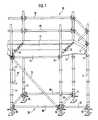
- the scaffold 10 according to FIG. 1 has stems 11 and scaffold floors 12 which are suspended in horizontally lying support bars 14 with the aid of hooking claws.
- the stems 11 are supported on height-adjustable feet 15 on the floor.
- Connection elements in the form of perforated disks 17 are fastened on the stems 11 at a distance 16 corresponding to the scaffold basic grid measurement system.
- Such perforated disks 17 can be equipped with the illustrated, but also with differently shaped holes and additional auxiliary devices.
- holes 29 of different sizes are formed in a known manner; namely for the scaffold elements 20 to be connected at right angles to one another, such as, for. B. the horizontal bars 18 and the support bars 14, the smaller holes 29.1 and for diagonally connected scaffolding elements 20, such as. B. the diagonal bars 19, the larger holes 29.2.
- the scaffolding elements 20 are primarily horizontal bars 18 and diagonal bars 19. These can have different lengths depending on their intended use. Horizontal bars 18 can also be used as a railing - as shown above in Fig. 1.
- the scaffold elements 20 are formed with cylindrical scaffold tubes 21, to which the connection heads 25 are welded.
- Known wedges 26 are guided through appropriate wedge openings and knocked down. They have a protruding pin or rivet 27 in the lower end area to prevent loss.
- a lateral recess 28 is designed in such a way that the wedge 26 can be placed parallel to the scaffold tube 21 in the raised position.
- connection head 25 has a connecting region 30, a perforated disk slot 31 and contact surfaces 32, by means of which it is supported on the stem 11 when it is inserted with the perforated disk slot 31 over a perforated disk 17 in a known manner. It has wedge openings 33.1 and 33.2 lying vertically one above the other through which the wedge 26 is guided.
- the upper wedge opening 33.1 is designed in the edge region with an inwardly projecting stop bead 34 for the engagement of the rivet 27 which serves to prevent loss. It is open in the rear pivoting area 33.3 in a known manner, so that the wedge 26 can be pivoted backwards when the heads of the rivet 27 are supported on the opposite stop beads 34.
- the wedge openings 33.1 and 33.2 are so wide that the heads of the rivet 27 can be carried out comfortably.
- the perforated disk slot 31 has rounded insertion corners 36, which are also designed in a known manner.
- connection head 25 is - seen in plan view (FIG. 4) - tapered inwards towards the stem and disc center 37, the outer boundary surfaces 38.1 and 38.2 being designed flat in the edge contours of their outwardly projecting beads, as is also the case was common with previous connection heads. This is done so that you can also connect diagonal bars and whose connection heads can be placed as closely as possible on the outer boundary surfaces of the connection heads of rods which are at right angles to one another.
- the outer boundary surfaces 38.1 and 38.2 have recesses 39.1 and 39.2 between their beads to save weight, which are also essentially designed in a known manner.
- the rear end surface 40 of the solid material areas of the front connection head part is, in deviation from the previous type, not designed as a plane, but as an outwardly inclined surface, as shown in FIGS. 2 and 5. It is advisable to choose the shape of a partial sphere. It is thereby achieved that, with the stability of the entire connection head 25 unchanged, the welding devices which are to be guided around the connection area can be guided more freely and can be designed more appropriately in order to achieve improved welding in the connection area 30.
- These end surface parts of end surface 40 which are designed as partial spherical surfaces, rise from partial cylinder surfaces 45, which have approximately the outer diameter 41 of tube 21.
- the upper partial cylinder surface 45 is cut only slightly in the middle in the middle of the rear swivel area 33.3 of the upper wedge opening 33.1.
- the upper and the lower partial cylinder surfaces merge into inclined surfaces 47.1 and 47.2 in the vertical edge regions, which directly adjoin the outer boundary surfaces 38.1 and 38.2, as clearly shown in FIG. 5 in particular.
- These inclined surfaces 47.1 and 47.2 extend approximately to the groove base 49 of the weld seam 50.
- the groove base 49 is delimited by an abutment ring surface 51 which extends over the entire welding area.
- the abutment ring surface 51 has as an inner boundary a circle which is approximately as large as the inner diameter 53 of the scaffold tube 21. Its outer diameter 54 is selected so that there is a favorable V-seam welding. It adjoins the abutment ring surface 51 with a conical surface 55 which widens towards the front and, together with the end surface 56 of the scaffold tube 21 which has just been cut off, limits the half V-seam for welding, this conical surface 55 only having a very slight kink in the side Sloping surfaces 47.1 and 47.2 merges practically continuously, so that there are no interruptions in the material flow during the continuous introduction of the weld seam.
- the combination of these design features ensures that, on the one hand, for interchangeability in the modular system, the dimensions of such connection heads which have been customary up to now are observed and, on the other hand, better welding can be achieved.
- inwardly projecting centering tabs 60 are provided which fit into the scaffold tube 21, the outer limit of which corresponds to the inside diameter 53 of the scaffold tube 21 and which, moreover, bevelled into the inner opening 61. They have a width that can be a little less than 1/8 of the circumference. Her size depends on the design options and the reasonable weight, taking into account that they are sufficiently stable during assembly and welding and do not hinder. They have already been designed in a similar way.
- connection area 30 with the abutment ring surface 51 and with the adjacent cone surface 55 and the inclusion of the other useful surface designs result in significantly improved welding conditions which significantly promote the safety of the connection for the components and thus significantly contribute to the overall safety of the scaffolding contribute.
- the same connection heads can also be used with the corresponding devices on a short piece of scaffolding tube for connecting diagonal bars and can also be used for other auxiliary devices by designing the piece of scaffolding tube accordingly.
- connection head (25) for scaffolding with connection devices has a connection area (30) which has centering tabs (60) and has an abutment ring surface (51) and a cone surface (55) to create favorable welding conditions.
Abstract
Description
Die Erfindung betrifft einen Anschlußkopf für Gerüst mit Verbindungsvorrichtungen mit folgenden Merkmalen:
- das Gerüst hat vertikale Stiele;
- an den vertikalen Stielen sind in einem dem Raster des Gerüstsystems entsprechenden Abstand ringförmige Anschlußteile befestigt;
- horizontal und/oder diagonal verlaufende langgestreckte Gerüstelemente sind an den ringförmigen Anschlußteilen mit Anschlußköpfen befestigt;
- die vertikalen Außenbegrenzungsflächen der Anschlußköpfe sind keilartig auf das Stiel- und Scheibenzentrum zusammenlaufend gestaltet;
- die Anschlußköpfe bestehen aus Stahlguß, Temperguß oder geschmiedetem Stahl;
- an langgestreckten Gerüstelementen befestigte Anschlußköpfe sind zentriert und angeschweißt.The invention relates to a connection head for scaffolding with connecting devices with the following features:
- the frame has vertical stems;
- Ring-shaped connecting parts are attached to the vertical stems at a distance corresponding to the grid of the scaffolding system;
- Horizontal and / or diagonal elongated scaffolding elements are attached to the ring-shaped connecting parts with connecting heads;
- The vertical outer boundary surfaces of the connection heads are designed in a wedge-like manner on the stem and disc center;
- The connection heads consist of cast steel, malleable cast iron or forged steel;
- Connection heads attached to elongated scaffolding elements are centered and welded on.
Anschlußköpfe mit den vorstehend abgedrucktenn Merkmalen werden seit langem verwendet und sind aus DE-PS 24 49 124 und praktischen Benutzungen der Firmen Layher ..., Eibensbach bekannt. Sie werden in der Regel aus Temperguß gefertigt und haben für die Zentrierung im anzuschweißenden Rohr wenigstens drei Zapfen oder Zentrierlappen, die auf den Innendurchmesser des Gerüstrohres abgestimmt sind. Eine geringfügig über den Innendurchmesser überstehende stirnseitige Positionierungsfläche, die normal auf der Rohrachse steht, ist nur im Bereich des Innendurchmessers des Rohres durchlaufend ausgeführt. Die Außenteile der Positionierungsfläche sind in den Bereichen von seitlichen, vertikal verlaufenden, nach hinten in Richtung auf das Gerüstrohr leicht geneigten Flächen unterbrochen. So kommt für die Befestigung nicht ringsum ein gleichmäßig durchlaufender Nahtgrund zustande. Vielmehr wird teilweise ein L-Nahtgrund angeboten und in den Seitenbereichen muß eine I-Naht gelegt werden. Dadurch und durch die Materialgegebenheiten ergeben sich beim Ringsum-Schweißen mit Schweißautomaten Ungleichmäßigkeiten mit ihren Folgen.Terminal heads with the features printed above have been used for a long time and are known from DE-PS 24 49 124 and practical uses of Layher ..., Eibensbach. They are usually made of malleable cast iron and have at least three pins or centering tabs for centering in the pipe to be welded, which are matched to the inside diameter of the scaffold tube. A positioning surface on the end face that projects slightly beyond the inner diameter and is normal to the pipe axis is only continuous in the area of the inner diameter of the pipe. The outer parts of the positioning surface are interrupted in the areas of lateral, vertical surfaces that are slightly inclined towards the scaffold tube. This means that there is no uniformly continuous seam base for the attachment all around. Rather, an L-seam base is sometimes offered and an I-seam must be placed in the side areas. This and the material conditions result in irregularities with their consequences when welding all round with automatic welding machines.
Die Erfindung ist nicht nur für die konkret bekannte Gestaltung geeignet, sondern auch für andere, ähnliche Anschlußköpfe mit zugehörigen Elementen, bei denen sich ähnliche Probleme ergeben.The invention is not only suitable for the specifically known design, but also for other, similar connection heads with associated elements, in which similar problems arise.
Aus DE 32 36 648 A1 ist ein Gerüst, insbesondere Baugerüst, mit tassenartigen Verbindungselementen auf den Stielen und in diese eingehängten Hakenanschlußköpfen bekannt. Solche Anschlußköpfe werden an den langgestreckten Gerüstelementen durch Schweißen befestigt. Dafür ist gemäß der zeichnerischen Darstellung ein Ansatz vorgesehen, der an das freie Ende des Horizontalriegels angepaßt und zweckmäßigerweise mittels einer Schweißnaht befestigt ist. Für das Einstecken, Zentrieren und Befestigen ist eine durchlaufende Konusfläche ohne besondere Ausricht-Hilfsmittel vorgesehen, die zu einer Verschweißung mit V-Naht oder L-Naht führt. Die genaue Ausrichtung zum Rohr bei der Verschweißung erfordert entsprechend ausrichtende Hilfsmittel, da eine Anstoßfläche bzw. Anstoßringfläche fehlt.From DE 32 36 648 A1 is a scaffold, in particular scaffolding, with cup-like connecting elements on the stems and known in these hooked hook connection heads. Such connection heads are attached to the elongated scaffolding elements by welding. For this purpose, an approach is provided according to the drawing, which is adapted to the free end of the horizontal bar and is expediently fastened by means of a weld seam. A continuous conical surface without special alignment aids is provided for insertion, centering and fastening, which leads to welding with V-seam or L-seam. The exact alignment to the pipe during welding requires appropriately aligning aids, since there is no abutment surface or abutment ring surface.
Aus DE 31 21 141 A1 - Fig. 7 - ist ein Anschlußkopf für eine tassenartige Verbindung bekannt, der für den Eingriff in das Ende des langgestreckten Gerüstelements einen Zentriereinsatz mit gerundeter Endausbildung aufweist, der in das Rohrende gesteckt wird. Dabei setzt der innere Rand des Rohrendes auf dem gerundeten Übergang zwischen Anschlußkopf und Zapfen in wenig genau definierter Form auf. Eine Fase am Rohr gestattet die Anbringung einer V-Naht.From DE 31 21 141 A1 - Fig. 7 - a connection head for a cup-like connection is known, which has a centering insert with a rounded end design for engagement in the end of the elongated scaffolding element, which is inserted into the pipe end. The inner edge of the pipe end is based on the rounded transition between the connection head and the spigot in a less precisely defined form. A chamfer on the pipe allows a V-seam to be attached.
Bei der Verbindung eines schlüssellochartigen Steckelementes mit einem Gerüstrohr nach DE 27 04 398 A1 ist diese derart ausgeführt, daß ein Keilformteil mit einer geraden Fläche vor die gerade Abschnittfläche des Rohres gelegt und in Teilbereichen mit V-Nähten angeschweißt ist. Eine integrierte Ausrichthilfe am Keilformteil fehlt.When a keyhole-like plug-in element is connected to a scaffold tube according to DE 27 04 398 A1, it is designed such that a wedge-shaped part with a straight surface is placed in front of the straight section surface of the tube and is welded in some areas with V-seams. An integrated alignment aid on the wedge molding is missing.
Aus DE 30 05 128 A1 ist ein Anschlußkopf mit den vorn genannten Merkmalen zu entnehmen, der einen üblichen Ansatz für das Befestigen an einem Rohr enthält. Nähere Einzelheiten über die Verbindung sind der Schrift nicht zu entnehmen.
Der Erfindung liegt die Aufgabe zugrunde, die Gestaltung der Verbindung des Anschlußkopfes mit dem Gerüstrohr so zu verbessern, daß sich bei guten Zentrier- und Ausrichtbedingungen günstigere Automatenschweißbedingungen ergeben.The invention has for its object to improve the design of the connection of the connection head with the scaffold tube so that there are more favorable automatic welding conditions with good centering and alignment conditions.
Erfindungsgemäß sind wenigstens die nachfolgend abgedruckten Merkmale vorgesehen:
- Das gerüstelementseitige Ende der Anschlußköpfe weist eine zum Gerüstelement passende, für das Verschweißen geeignete Ausbildung des Verbindungsbereiches (30) auf;
- dafür sind in das als Gerüstrohr (21) ausgebildete Gerüstelement ragende, passende Zentrierhilfsteile vorgesehen;
- es ist eine Anstoßringfläche (51) gebildet, deren Außendurchmesser (54) kleiner ist, als der Außendurchmesser (41) des Gerüstrohres (21);
- nach außen schließt sich daran eine sich nach vorn erweiternde durchlaufende Konusfläche an,
Dadurch, daß eine ringsum stetig durchlaufende, sich vom Innenrand nach außen mit gleicher Ringbreite erstreckende Anstoßringfläche ausgebildet ist, die auf ihrem Außendurchmesser in eine nach vorn sich erweiternde als Konusfläche bezeichnete Teilkegelfläche übergeht, ergibt sich ein durchlaufender Nutgrund, der die Form einer halben V-Naht hat, wobei die Rohrkante infolge des Schmelzvorganges gleichmäßig abgeschmolzen werden kann, während die angrenzende Tempergußwand überall nahezu gleichmäßige Bedingungen des Grundes bietet, die somit zu einem gleichmäßigen Abbrand, einem gleichmäßigen Nahtbild und damit zu einer ringsum gleichmäßigen, hochfesten Verschweißung gemäß den gewählten Materialbedingungen führt. Dazu trägt weiter bei, daß die Konusfläche in den im wesentlichen vertikalen seitlichen Randbereichen mit nahezu kontinuierlichem Übergang in die auf gleichem Außenradius und mit annähernd gleicher Neigung verlaufende Keilflächenteile übergeht.According to the invention, at least the features printed below are provided:
- The end of the connection heads on the scaffold element has a design of the connection area (30) that is suitable for the scaffold element and is suitable for welding;
- For this purpose, suitable centering auxiliary parts projecting into the scaffolding tube (21) are provided;
- An abutment ring surface (51) is formed, the outer diameter (54) is smaller than the outer diameter (41) of the scaffold tube (21);
- to the outside is a continuous conical surface that widens towards the front,
The fact that an all round continuous abutment ring surface is formed, which extends from the inner edge to the outside with the same ring width, and whose outer diameter merges into a part-conical surface which widens towards the front and is called a conical surface, resulting in a continuous groove base which has the shape of a half V Seam has, whereby the pipe edge can be melted evenly as a result of the melting process, while the adjacent malleable cast iron wall offers almost uniform conditions of the bottom everywhere, which thus leads to a uniform burn-off, a uniform seam pattern and thus to a uniform, high-strength welding according to the selected material conditions . This also contributes to the fact that the conical surface merges in the essentially vertical lateral edge regions with an almost continuous transition into the wedge surface parts running on the same outer radius and with approximately the same inclination.
Zweckmäßigerweise schließt sich an die Konusfläche eine Zylinderfläche an, deren Durchmesser dem Außendurchmesser des Gerüstrohres gleich ist oder geringfügig größer als dieser ist und die in den vertikalen Randbereichen in die Keilflächenteile übergeht. Auch dadurch werden bei dem konstuktiv durch das Baukastensystem vorgegebenen Rahmen die Schweißbedingungen verbessert.Expediently, the conical surface is adjoined by a cylindrical surface, the diameter of which is equal to or slightly larger than the outer diameter of the scaffold tube and which merges into the wedge surface parts in the vertical edge regions. This also improves the welding conditions in the frame that is structurally predetermined by the modular system.
In weiterer sinnvoller Ausgestaltung kann der Anschlußkopf gemäß Anspruch 4 in seinen über den Durchmesser des Gerüstrohres hinausragenden Teilen rückseitig von einer sich an den zylindrischen Teil im Verbindungsbereich anschießenden Kugelteilfläche begrenzt sein. So ist die für den aus der Belastung resultierenden Kraftfluß erforderliche Materialmenge an günstigen Stellen angeordnet und es sind hinreichend Freiräume für das Ringsum-Verschweißen ohne Beeinträchtigung der Stabilität des Anschlußkopfes bei geringerem Materialaufwand und günstigen Platzbedingungen für die Schweißgeräteteile erzielt.In a further expedient embodiment, the connection head, according to claim 4, in its parts projecting beyond the diameter of the scaffold tube, can be bounded on the back by a spherical partial surface which adjoins the cylindrical part in the connection area. Thus, the amount of material required for the flow of force resulting from the load is arranged at favorable points and sufficient space for all-round welding is achieved without impairing the stability of the connection head with less material expenditure and favorable space conditions for the welding machine parts.
Weitere Einzelheiten, Vorteile, Merkmale und Gesichtspunkte der Erfindung ergeben sich auch aus dem nachfolgenden, anhand der Zeichnungen abgehandelten Beschreibungsteil.Further details, advantages, features and aspects of the invention also emerge from the following description part, which is dealt with on the basis of the drawings.
Ein Ausführungsbeispiel der Erfindung wird nachfolgend anhand der Zeichnungen näher erläutert und beschrieben.An embodiment of the invention is explained and described in more detail below with reference to the drawings.
Es zeigen:
- Fig. 1 Die schematische Schrägansicht eines Teiles eines Gerüstes mit Anschlußköpfen, die gemäß den weiteren Figuren nach der Erfindung gestaltet sind;
- Fig. 2 die Teil-Darstellung eines Anschlußknotens, teilweise im Vertikalschnitt und teilweise in der Seitenansicht, wobei der Anschlußkopf und die ihn umgebenden Bereiche dargestellt sind;
- Fig. 3 eine vergrößerte Schnittdarstellung des in Fig. 2 mit einem Kreis 3 gekennzeichneten Bereiches im Zustand vor der Verschweißung;
- Fig. 4 eine Teil-Darstellung eines Anschlußknotens mit Lochscheibe, wobei nur ein Anschlußkopf mit angrenzendem Gerüstrohrbereich und Teile der Lochscheibe dargestellt sind, teilweise im Schnitt und teilweise in der Draufsicht;
- Fig. 5 eine Schrägansicht eines Anschlußkopfes schräg von hinten oben auf den Verbindungsbereich, wobei kein Gerüstrohr gezeigt ist.
- Fig. 1 The schematic oblique view of a part of a frame with connection heads, which are designed according to the other figures according to the invention;
- 2 shows the partial representation of a connection node, partly in vertical section and partly in side view, the connection head and the areas surrounding it being shown;
- 3 is an enlarged sectional view of the area marked with a circle 3 in FIG. 2 in the state before the welding;
- 4 shows a partial representation of a connection node with perforated disk, only one connection head with adjoining scaffold tube area and parts of the perforated disk being shown, partly in section and partly in plan view;
- Fig. 5 is an oblique view of a connection head obliquely from behind on top of the connection area, wherein no scaffold tube is shown.
Das Gerüst 10 nach Fig. 1 hat Stiele 11 und Gerüstböden 12, die mit Hilfe von Einhängeklauen in horizontal liegende Tragriegel 14 eingehängt sind. Die Stiele 11 stützen sich auf höheneinstellbaren Füßen 15 am Boden ab. In einem dem Gerüst-Grundraster-Maßsystem entsprechenden Abstand 16 sind Anschlußelemente in Form von Lochscheiben 17 auf den Stielen 11 befestigt. Solche Lochscheiben 17 können mit den dargestellten, jedoch auch mit anders geformten Löchern und zusätzlichen Hilfseinrichtungen ausgestattet sein. Bei diesem bevorzugten Ausführungsbeispiel sind unterschiedlich große Löcher 29 in bekannter Weise ausgebildet; und zwar für die unter rechten Winkeln zueinander anzuschließenden Gerüstelemente 20 , wie z. B. die Horizotalriegel 18 und die Tragriegel 14, die kleineren Löcher 29.1 und für diagonal anzuschließende Gerüstelemente 20, wie z. B. die Diagonalstäbe 19, die größeren Löcher 29.2. Die Gerüstelemente 20 sind vor allem Horizontalriegel 18 und Diagonalstäbe 19. Diese können je nach ihrem Einsatzzweck unterschiedliche Längen haben. Horizontalriegel 18 können auch - wie oben in Fig. 1 dargestellt - als Geländer benutzt werden.The
Wie die weiteren Zeichnungen zeigen, sind die Gerüstelemente 20 mit zylindrischen Gerüstrohren 21, an die die Anschlußköpfe 25 angeschweißt sind, gebildet. Durch entsprechende Keilöffnungen sind an sich bekannte Keile 26 geführt und festgeschlagen. Sie haben im unteren Endbereich als Verliersicherung einen durchragenden Stift oder Niet 27. Eine seitliche Ausnehmung 28 ist so gestaltet, daß man den Keil 26 in der hochgezogenen Stellung parallel zum Gerüstrohr 21 legen kann.As the other drawings show, the
Jeder Anschlußkopf 25 hat einen Verbindungsbereich 30, einen Lochscheiben-Schlitz 31 sowie Anlageflächen 32, mittels deren er sich an dem Stiel 11 abstützt, wenn er mit dem Lochscheiben-Schlitz 31 über eine Lochscheibe 17 in bekannter Weise gesteckt ist. Er hat vertikal übereinander liegende Keilöffnungen 33.1 und 33.2, durch die der Keil 26 geführt ist. Die obere Keilöffnung 33.1 ist im Randbereich mit einem nach innen ragenden Anschlagwulst 34 für die Anlage des der Verliersicherung dienenden Nietes 27 gestaltet. Sie ist im hinteren Schwenkbereich 33.3 in bekannter Weise offen, so daß man den Keil 26 nach hinten schwenken kann, wenn sich die Köpfe des Niet 27 an den gegenüberliegenden Anschlagwülsten 34 abstützen.Each
Im übrigen sind die Keilöffnungen 33.1 und 33.2 so breit, daß die Köpfe des Niet 27 bequem durchgeführt werden können. Zur Verbesserung des Aufsteckens des Anschlußkopfes 25 auf die Lochscheibe 17 hat der Lochscheiben-Schlitz 31 ausgerundete Einführecken 36, die ebenfalls in bekannter Weise gestaltet sind.For the rest, the wedge openings 33.1 and 33.2 are so wide that the heads of the
Der ganze Anschlußkopf 25 ist - in der Draufsicht (Fig. 4) gesehen - keilartig nach innen auf das Stiel- und Scheibenzentrum 37 zulaufend gestaltet, wobei die Außenbegrenzungsflächen 38.1 und 38.2 in den Randkonturen ihrer nach außen ragenden Wülste eben gestaltet sind, wie es auch bei bisherigen Anschlußköpfen üblich war. Das ist so gemacht, damit man auch diagonal verlaufende Stäbe anschließen und deren Anschlußköpfe möglichst eng an die Außenbegrenzungsflächen der Anschlußköpfe rechtwinklig zueinander stehender Stäbe anlegen kann. Die Außenbegrenzungsflächen 38.1 und 38.2 haben zur Gewichtseinsparung zwischen ihren Wülsten Vertiefungen 39.1 und 39.2, die ebenfalls im wesentlichen in bekannter Weise gestaltet sind.The
Die rückseitige Abschlußfläche 40 der massiven Materialbereiche des vorderen Anschluß-Kopfteiles ist in Abweichung von der bisherigen Art nicht als Ebene, sondern als nach außen geneigte Fläche gestaltet, wie es die Fig. 2 und 5 zeigen. Dabei wählt man zweckmäßig die Form einer Teilkugel. Dadurch erreicht man, daß bei unveränderter Stabilität des ganzen Anschlußkopfes 25 die für die Befestigung um den Verbindungsbereich herumzuführenden Schweißeinrichtungen freier geführt und geeigneter gestaltet werden können, um eine verbesserte Verschweißung im Verbindungsbereich 30 zu erzielen. Diese als Teilkugelflächen ausgebildeten Abschlußflächenteile der Abschlußfläche 40 erheben sich aus Zylinderteilflächen 45, die etwa den Außendurchmesser 41 des Rohres 21 haben. Die obere Zylinderteilfläche 45 ist nur im oberen Bereich in der Mitte ganz etwas von dem hinteren Schwenkbereich 33.3 der oberen Keilöffnung 33.1 angeschnitten. Die obere und die untere Zylinderteilfläche gehen in den vertikalen Randbereichen, die unmittelbar an die Außenbegrenzungsflächen 38.1 und 38.2 anschließen, in Schrägflächen 47.1 und 47.2 über - wie es inbesondere Fig. 5 - deutlich zeigt. Diese Schrägflächen 47.1 und 47.2 reichen in etwa bis zum Nutgrund 49 der Schweißnaht 50.The
Der Nutgrund 49 wird von einer über den ganzen Schweißbereich durchlaufenden Anstoß-Ringfläche 51 begrenzt. Die Anstoß-Ringfläche 51 hat als innere Begrenzung einen Kreis, der etwa so groß ist wie der Innendurchmesser 53 des Gerüstrohres 21. Ihr Außendurchmesser 54 ist so gewählt, daß sich eine günstige V-Naht-Verschweißung ergibt. Es schließt sich an die Anstoß-Ringfläche 51 eine sich nach vorn erweiternde Konusfläche 55 an, die zusammen mit der gerade abgeschnittenen Endfläche 56 des Gerüstrohres 21 die halbe V-Naht zum Verschweißen begrenzt, wobei diese Konusfläche 55 nur mit ganz geringer Abknickung in die seitlichen Schrägflächen 47.1 und 47.2 praktisch kontinuierlich übergeht, so daß sich keine Unterbrechungen des Materialflusses beim durchlaufenden Einbringen der Schweißnaht ergeben. Durch die Vereinigung dieser Gestaltungsmerkmale ist gewährleistet, daß man einerseits zur Austauschbarkeit im Baukastensystem die bisher üblichen Abmessungen solcher Anschlußköpfe einhalten und andererseits trotzdem bessere Verschweißung erzielen kann.The
Zur Zentrierung beim Aufsetzen des Anschlußkopfes 25 auf das Gerüstrohr 21 sind nach innen ragende, in das Gerüstrohr 21 passende Zentrierlappen 60 vorgesehen, deren äußere Begrenzung dem Innendurchmesser 53 des Gerüstrohres 21 entspricht und die im übrigen abgeschrägt in die Innenöffnung 61 übergehen. Sie haben eine Breite, die etwas weniger als 1/8 des Umfanges betragen kann. Ihre Größe richtet sich nach den Gestaltungsmöglichkeiten und dem vertretbaren Gewicht unter Berücksichtigung dessen, daß sie beim Montieren und Verschweißen hinreichend stabil sind und nicht behindern. Sie sind in ähnlicher Weise schon bisher gestaltet worden.For centering when the
Durch die vorteilhafte, neue Gestaltung des Verbindungsbereiches 30 mit der Anstoß-Ringfläche 51 und mit der angrenzenden Konusfläche 55 und Einbeziehung der übrigen sinnvollen Flächengestaltungen ergeben sich wesentlich verbesserte Schweißbedingungen, die die Sicherheit der Verbindung für die Bauteile wesentlich fördern und somit zur Gesamtsicherheit der Gerüste wesentlich beitragen. Gleiche Anschlußköpfe können mit den entsprechenden Einrichtungen an einem kurzen Gerüstrohrstück auch zum Anschluß von Diagonalstäben verwendet werden und auch für sonstige Hilfseinrichtungen benutzt werden, indem das Gerüstrohrstück entsprechend gestaltet wird.The advantageous, new design of the
Die nachfolgend abgedruckte Zusammenfassung ist Bestandteil der Offenbarung der Erfindung:The summary printed below is part of the disclosure of the invention:
Der Anschlußkopf (25) für Gerüste mit Verbindungsvorrichtungen hat einen Verbindungsbereich (30), der Zentrierlappen (60) aufweist und eine Anstoß-Ringfläche (51) sowie eine Konusfläche (55) zur Schaffung günstiger Schweißbedingungen besitzt.The connection head (25) for scaffolding with connection devices has a connection area (30) which has centering tabs (60) and has an abutment ring surface (51) and a cone surface (55) to create favorable welding conditions.
Claims (5)
- das Gerüst hat vertikale Stiele;
- an den vertikalen Stielen sind in einem dem Raster des Gerüstsystems entsprechenden Abstand ringförmige Anschlußteile befestigt;
- horizontal und/oder diagonal verlaufende langgestreckte Gerüstelemente sind an den ringförmigen Anschlußteilen mit Anschlußköpfen befestigt;
- die vertikalen Außenbegrenzungsflächen der Anschlußköpfe sind keilartig auf das Stiel- und Scheibenzentrum zusammenlaufend gestaltet;
- die Anschlußköpfe bestehen aus Stahlguß, Temperguß oder geschmiedetem Stahl;
- an langgestreckten Gerüstelementen befestigte Anschlußköpfe sind zentriert und angeschweißt; ferner sind folgende Merkmale vorgesehen:
- das gerüstelementseitige Ende der Anschlußköpfe weist eine zum Gerüstelement passende, für das Verschweißen geeignete Ausbildung des Verbindungsbereiches (30) auf;
- dafür sind in das als Gerüstrohr (21) ausgebildete Gerüstelement ragende, passende Zentrierhilfsteile vorgesehen;
- es ist eine Anstoßringfläche (51) gebildet, deren Außendurchmesser (54) kleiner ist, als der Außendurchmesser (41) des Gerüstrohres (21);
- nach außen schließt sich daran eine sich nach vorn erweiternde Konusfläche (55)an.1. Connection head for scaffolding with connecting devices with the following features:
- the frame has vertical stems;
- Ring-shaped connecting parts are attached to the vertical stems at a distance corresponding to the grid of the scaffolding system;
- Horizontal and / or diagonal elongated scaffolding elements are attached to the ring-shaped connecting parts with connecting heads;
- The vertical outer boundary surfaces of the connection heads are designed in a wedge-like manner on the stem and disc center;
- The connection heads consist of cast steel, malleable cast iron or forged steel;
- Connection heads attached to elongated scaffolding elements are centered and welded on; the following features are also provided:
- The end of the connection heads on the scaffolding element has a design of the connection area (30) that is suitable for the scaffolding element and is suitable for welding;
- For this purpose, suitable centering auxiliary parts projecting into the scaffolding tube (21) are provided;
- An abutment ring surface (51) is formed, the outer diameter (54) is smaller than the outer diameter (41) of the scaffold tube (21);
- To the outside there is a conical surface (55) which widens towards the front.
dadurch gekennzeichnet, daß die Konusfläche (55) in den im wesentlichen vertikalen Randbereichen des Anschlußkopfes (25) in etwa gleich geneigte Keilflächenteile (47.1, 47.2) übergeht.2. Connection head according to claim 1,
characterized in that the conical surface (55) merges into the substantially vertical edge regions of the connection head (25) in approximately equally inclined wedge surface parts (47.1, 47.2).
dadurch gekennzeichnet, daß sich an die Kegelfläche (55) eine Zylinderfläche (45) anschließt, deren Durchmesser dem Außendurchmesser (41) des Gerüstrohres (21) gleich ist oder geringfügig größer als dieser ist und die in den vertikalen Randbereichen in die Keilflächenteile (47.1, 47.2) übergeht.3. Connection head according to claim 1 or 2,
characterized in that a cylindrical surface (45) adjoins the conical surface (55), the diameter of which is equal to or slightly larger than the outer diameter (41) of the scaffold tube (21) and which in the vertical edge regions into the wedge surface parts (47.1, 47.2) passes.
dadurch gekennzeichnet, daß der Anschlußkopf (25) in seinen über den Außendurchmesser (41) des Gerüstrohres (21) hinausragenden Teilen mit einer rückseitigen Abschlußfläche (40) aus nach vor geneigten Kugelteilflächen versehen ist, die sich aus den Zylinderteilfächen (45) erheben.4. Connection head according to at least one of the other claims,
characterized in that the connection head (25), in its parts projecting beyond the outer diameter (41) of the scaffold tube (21), is provided with a rear end face (40) made of forwardly inclined spherical partial surfaces which rise from the cylindrical partial surfaces (45).
- das Gerüst hat vertikale Stiele;
- an den vertikalen Stielen sind in einem dem Raster des Gerüstsystems entsprechenden Abstand ringförmige Lochscheiben befestigt;
- horizontal und/oder diagonal verlaufende langgestreckte Gerüstelemente sind an den ringförmigen Lochscheiben mit Anschlußköpfen befestigt;
- die Anschlußköpfe greifen mit Schlitzen über die Lochscheiben;
- die Anschlußköpfe haben senkrecht übereinander liegende Keilöffnungen für durch die Keilöffnungen und die Scheibenlöcher greifende Keile;
- die vertikalen Außenbegrenzungsflächen der Köpfe sind keilartig auf das Stiel- und Scheibenzentrum zusammenlaufend gestaltet;
- Anlagestützflächen der Anschlußköpfe haben eine größere Höhe als der Durchmesser oder die Höhe der langgestreckten Gerüstelemente;
- die Anschlußköpfe bestehen aus Stahlguß, Temperguß oder geschmiedetem Stahl;
- an langgestreckten Gerüstelementen befestigte Anschlußköpfe sind mit in deren Profil eingreifenden Fortsätzen zentriert und angeschweißt;
- die Anschlußköpfe (25) reduzieren sich von den äußeren Begrenzungen der Anlagestützen allmählich auf die Außendurchmesser (41) bzw. Höhen der langgestreckten Gerüstelemente (20);
dadurch gekennzeichnet,
daß folgende Merkmale vorgesehen sind:
- das gerüstrohrseitige Ende weist eine passende, für das Verschweißen geeignete Ausbildung des Verbindungsbereiches (30) auf;
- dafür sind nach innen ragende, in das Rohr passende Zentrierlappen (60) ausgebildet;
- es ist eine Anstoß-Ringfläche (51) gebildet, deren Außendurchmesser (54) kleiner ist, als der Außendurchmesser (41) des Gerüstrohres (21);
- nach außen schließt sich daran eine sich nach vorn erweiternde Konusfläche (55) an;
- diese geht in den vertikalen Randbereichen des Anschlußkopfes (25) in etwa gleich geneigte Keilflächenteile (47.1, 47.2) über;
- an die Konusfläche (55) schließt sich eine Zylinderfläche (45) an, deren Durchmesser dem Außendurchmesser (41) des Gerüstrohres (21) gleich ist oder geringfügig größer als dieser ist und die in den vertikalen Randbereichen in die Keilflächen (47.1, 47.2) übergeht.5. Connection head for scaffolding with connecting devices with the following features:
- the frame has vertical stems;
ring-shaped perforated disks are fastened to the vertical stems at a distance corresponding to the grid of the scaffolding system;
- Horizontal and / or diagonal elongated scaffolding elements are attached to the annular perforated disks with connection heads;
- The connection heads engage with slots over the perforated disks;
- The connection heads have vertically superimposed wedge openings for wedges reaching through the wedge openings and the disk holes;
- The vertical outer boundary surfaces of the heads are wedge-like designed to converge on the stem and disc center;
- System support surfaces of the connection heads have a greater height than the diameter or the height of the elongated scaffolding elements;
- The connection heads consist of cast steel, malleable cast iron or forged steel;
- Connection heads attached to elongated scaffolding elements are centered and welded with extensions which engage in their profile;
- The connection heads (25) are gradually reduced from the outer limits of the bearing supports to the outer diameter (41) or heights of the elongated scaffolding elements (20);
characterized,
that the following features are provided:
- The end of the scaffold tube has a suitable design of the connection area (30) suitable for welding;
- For this purpose, inwardly projecting centering tabs (60) are formed in the tube;
- An abutment ring surface (51) is formed, the outer diameter (54) is smaller than the outer diameter (41) of the scaffold tube (21);
- To the outside there is a conical surface (55) which widens towards the front;
- This merges in the vertical edge areas of the connection head (25) in approximately equally inclined wedge surface parts (47.1, 47.2);
- The conical surface (55) is followed by a cylindrical surface (45), the diameter of which is equal to or slightly larger than the outer diameter (41) of the scaffold tube (21) and which in the vertical edge regions into the wedge surfaces (47.1, 47.2) transforms.
Applications Claiming Priority (2)
| Application Number | Priority Date | Filing Date | Title |
|---|---|---|---|
| DE3934857A DE3934857A1 (en) | 1989-10-19 | 1989-10-19 | CONNECTING HEAD FOR SCAFFOLDING |
| DE3934857 | 1989-10-19 |
Publications (4)
| Publication Number | Publication Date |
|---|---|
| EP0423516A2 true EP0423516A2 (en) | 1991-04-24 |
| EP0423516A3 EP0423516A3 (en) | 1992-03-04 |
| EP0423516B1 EP0423516B1 (en) | 1996-11-27 |
| EP0423516B2 EP0423516B2 (en) | 2001-03-07 |
Family
ID=6391775
Family Applications (1)
| Application Number | Title | Priority Date | Filing Date |
|---|---|---|---|
| EP90118546A Expired - Lifetime EP0423516B2 (en) | 1989-10-19 | 1990-09-27 | Scaffolding tube with connecting head |
Country Status (11)
| Country | Link |
|---|---|
| US (1) | US5127757A (en) |
| EP (1) | EP0423516B2 (en) |
| JP (1) | JP3043389B2 (en) |
| AT (1) | ATE145696T1 (en) |
| CA (1) | CA2027945C (en) |
| DE (2) | DE3934857A1 (en) |
| DK (1) | DK0423516T4 (en) |
| ES (1) | ES2097125T5 (en) |
| FI (1) | FI93136C (en) |
| NO (1) | NO177913C (en) |
| PT (2) | PT95621A (en) |
Cited By (4)
| Publication number | Priority date | Publication date | Assignee | Title |
|---|---|---|---|---|
| WO1996019626A1 (en) * | 1994-12-20 | 1996-06-27 | Eugenio Del Castillo Cabello | Structure support with multidirectional node |
| WO1999028573A1 (en) * | 1997-12-01 | 1999-06-10 | Plettac Ag | Connecting device for a bearer |
| US8439166B2 (en) | 2008-01-24 | 2013-05-14 | Wilhelm Layher Verwaltungs-Gmbh | Vertical frame intended for the construction of a frame support, a supporting scaffold and/or a supporting scaffold tower |
| US8978822B2 (en) | 2006-10-11 | 2015-03-17 | Wilhelm Layher Verwaltungs-Gmbh | Vertical frame of metal |
Families Citing this family (28)
| Publication number | Priority date | Publication date | Assignee | Title |
|---|---|---|---|---|
| FR2660708B1 (en) * | 1990-04-04 | 1993-05-21 | Perruelle Claude | ASSEMBLY PART FOR LONGIFORM ELEMENTS. |
| CA2201535C (en) * | 1997-04-02 | 2006-09-19 | Aluma Systems Corp. | Scaffolding connector |
| DE19806094A1 (en) * | 1998-02-14 | 1999-08-19 | Layher W Vermogensverw Gmbh | Arrangement of structural elements of a spatial structure |
| DE19806093B4 (en) * | 1998-02-14 | 2012-07-05 | Wilhelm Layher Verwaltungs-Gmbh | Support structure element arrangement of a space structure |
| DE19939197A1 (en) * | 1999-08-18 | 2001-02-22 | Hese Gmbh Maschf Ernst | Support frame for a continuous conveyor system |
| PT1179650E (en) * | 2000-03-21 | 2004-04-30 | Ulma C Y E S Coop | APPROPRIATE STAGE |
| SE519230C2 (en) * | 2000-09-06 | 2003-02-04 | Pluseight Technology Ab | Device for connecting scaffolding elements |
| SE521500C2 (en) * | 2001-03-27 | 2003-11-04 | Pluseight Safety Ab | Device for personal protection at scaffolding and method for protecting persons by such device |
| DE10128955A1 (en) * | 2001-06-15 | 2002-12-19 | Peri Gmbh | Demountable multi-stage scaffolding comprises several walk-on floor levels supported by vertical struts with railings fitted on through adapter attachable to rosette support above floor at distance not restricted by spacing between rosettes |
| SE525339C2 (en) * | 2002-09-27 | 2005-02-01 | Pluseight Safety Ab | Device for personal protection at scaffolding |
| DE10308853B3 (en) * | 2003-02-27 | 2004-09-09 | Wilhelm Layher Vermögensverwaltungs-Gmbh | Crash prevention device for structures with flat roofs comprises a rail and a bracket both having horizontally and/or diagonally running rod elements connected by vertical handles |
| DE10317842B4 (en) * | 2003-04-16 | 2012-03-01 | Wilhelm Layher Verwaltungs-Gmbh | Suspension unit |
| US20060039746A1 (en) * | 2004-08-11 | 2006-02-23 | Stringer Matthew D | Connecting device for scaffolding |
| US20070036842A1 (en) * | 2005-08-15 | 2007-02-15 | Concordia Manufacturing Llc | Non-woven scaffold for tissue engineering |
| US7845134B2 (en) * | 2005-09-16 | 2010-12-07 | Lacey Jr Harvey W | Structure and a method for constructing the structure |
| DE102007018314A1 (en) * | 2007-04-18 | 2008-11-06 | Wilhelm Layher Verwaltungs-Gmbh | Support for a space structure and connection arrangement for a railing device and method for securing a railing device to a support |
| NL2004011C2 (en) * | 2009-12-23 | 2011-06-27 | Scafom Internat B V | ELEMENT OF A MODULAR SCAFFOLDING SYSTEM AND A METHOD OF MANUFACTURING IT. |
| DE102010000472A1 (en) | 2010-02-19 | 2011-08-25 | Wilhelm Layher Verwaltungs-GmbH, 74363 | Scaffolding and method for mounting or dismounting such scaffolding |
| DE202010013128U1 (en) | 2010-12-15 | 2011-03-03 | Wilhelm Layher Verwaltungs-Gmbh | Connecting head device for connection to a perforated disc of a scaffolding handle or for coupling a plurality of perforated discs scaffolding posts |
| DE102011001796A1 (en) | 2011-04-05 | 2012-10-11 | Wilhelm Layher Verwaltungs-Gmbh | scaffolding post |
| WO2012163340A1 (en) * | 2011-06-01 | 2012-12-06 | Wilhelm Layher Verwaltungs-Gmbh | Arrangement of a scaffolding component and of a vertical scaffolding element |
| US8757321B2 (en) * | 2011-12-06 | 2014-06-24 | Ssa Terminals (Long Beach) Llc | Long reach apparatus |
| US9835188B2 (en) * | 2013-03-14 | 2017-12-05 | Titan Formwork Systems Llc | Universal wedge clamp |
| DK3012385T3 (en) | 2014-10-20 | 2018-11-26 | Jerslev Stilladsservice As | Scaffolding Safety Railing |
| SE538860C2 (en) * | 2015-05-21 | 2017-01-10 | Mon Zon Dev Ab | Flexible fastening unit for a beam |
| AU2018215859A1 (en) * | 2017-02-03 | 2019-08-22 | Masonry Scaffolding Solutions Limited | Scaffold system |
| DE102019133939A1 (en) | 2019-12-11 | 2021-06-17 | Wilhelm Layher Verwaltungs-Gmbh | DEVICE FOR THE DETACHABLE FIXING OF AT LEAST ONE RAILING EQUIPMENT TO A SCAFFOLDING ELEMENT |
| BE1029469B1 (en) * | 2021-06-07 | 2023-01-09 | Afix Group Nv | KEY |
Citations (7)
| Publication number | Priority date | Publication date | Assignee | Title |
|---|---|---|---|---|
| FR1362837A (en) * | 1963-06-28 | 1964-06-05 | Wilhelm Layher | Spring connector for metal scaffolding |
| DE2737859A1 (en) † | 1977-08-23 | 1979-03-08 | Eberhard Layher | METAL PIPE FRAMEWORK |
| DE2449124C3 (en) * | 1974-10-16 | 1980-01-03 | Eberhard 7129 Gueglingen Layher | Connection device for scaffolding elements |
| DE3121141A1 (en) * | 1981-05-27 | 1982-12-30 | Rodiac Intercessor Ltd., Zug | Rapid-construction scaffolding and coupling unit for connecting a stand tube, in particular, to longitudinal and/or transverse and/or diagonal members, and stand rosette with appertaining coupling member |
| DE3236648A1 (en) * | 1982-10-04 | 1984-04-05 | Plettac Gmbh Stahlbau Und Gesenkschmiede, 5970 Plettenberg | SCAFFOLDING, ESPECIALLY CONSTRUCTION SCAFFOLDING |
| EP0276487A2 (en) * | 1987-01-24 | 1988-08-03 | Langer geb. Layher, Ruth | Scaffolding with connecting devices |
| JPH05500836A (en) † | 1989-05-05 | 1993-02-18 | インターナショナル・ペーパー・カンパニー | Ozonation treatment of chlorinated pulp with chlorine dioxide/chlorine |
Family Cites Families (5)
| Publication number | Priority date | Publication date | Assignee | Title |
|---|---|---|---|---|
| US3598433A (en) * | 1969-09-16 | 1971-08-10 | Anthony P Savickas | Molded plastic fitting |
| DE2704398C3 (en) * | 1977-02-03 | 1980-08-21 | Plettac Gmbh, 5970 Plettenberg | Framework that can be assembled from uprights and bars |
| US4159187A (en) * | 1978-08-30 | 1979-06-26 | Schaefer Equipment Incorporated | Five piece brake lever connection |
| DE3005128A1 (en) * | 1980-02-12 | 1981-08-20 | Eberhard 7129 Güglingen Layher | Building kit for model scaffolding - has hollow pipes linked to joints using sprung clamps |
| DE3824823A1 (en) * | 1988-07-21 | 1990-01-25 | Langer Ruth Geb Layher | CONNECTOR TRAINING FOR HORIZONTAL BRACKETS FROM SCAFFOLDINGS |
-
1989
- 1989-10-19 DE DE3934857A patent/DE3934857A1/en not_active Withdrawn
-
1990
- 1990-09-27 AT AT90118546T patent/ATE145696T1/en not_active IP Right Cessation
- 1990-09-27 DE DE59010581T patent/DE59010581D1/en not_active Expired - Lifetime
- 1990-09-27 DK DK90118546T patent/DK0423516T4/en active
- 1990-09-27 EP EP90118546A patent/EP0423516B2/en not_active Expired - Lifetime
- 1990-09-27 ES ES90118546T patent/ES2097125T5/en not_active Expired - Lifetime
- 1990-10-01 FI FI904814A patent/FI93136C/en active IP Right Grant
- 1990-10-16 JP JP2275511A patent/JP3043389B2/en not_active Expired - Lifetime
- 1990-10-18 PT PT95621A patent/PT95621A/en active IP Right Grant
- 1990-10-18 CA CA002027945A patent/CA2027945C/en not_active Expired - Lifetime
- 1990-10-18 NO NO904522A patent/NO177913C/en not_active IP Right Cessation
- 1990-10-19 US US07/599,855 patent/US5127757A/en not_active Expired - Lifetime
-
1992
- 1992-04-09 PT PT8464U patent/PT8464U/en not_active IP Right Cessation
Patent Citations (7)
| Publication number | Priority date | Publication date | Assignee | Title |
|---|---|---|---|---|
| FR1362837A (en) * | 1963-06-28 | 1964-06-05 | Wilhelm Layher | Spring connector for metal scaffolding |
| DE2449124C3 (en) * | 1974-10-16 | 1980-01-03 | Eberhard 7129 Gueglingen Layher | Connection device for scaffolding elements |
| DE2737859A1 (en) † | 1977-08-23 | 1979-03-08 | Eberhard Layher | METAL PIPE FRAMEWORK |
| DE3121141A1 (en) * | 1981-05-27 | 1982-12-30 | Rodiac Intercessor Ltd., Zug | Rapid-construction scaffolding and coupling unit for connecting a stand tube, in particular, to longitudinal and/or transverse and/or diagonal members, and stand rosette with appertaining coupling member |
| DE3236648A1 (en) * | 1982-10-04 | 1984-04-05 | Plettac Gmbh Stahlbau Und Gesenkschmiede, 5970 Plettenberg | SCAFFOLDING, ESPECIALLY CONSTRUCTION SCAFFOLDING |
| EP0276487A2 (en) * | 1987-01-24 | 1988-08-03 | Langer geb. Layher, Ruth | Scaffolding with connecting devices |
| JPH05500836A (en) † | 1989-05-05 | 1993-02-18 | インターナショナル・ペーパー・カンパニー | Ozonation treatment of chlorinated pulp with chlorine dioxide/chlorine |
Cited By (5)
| Publication number | Priority date | Publication date | Assignee | Title |
|---|---|---|---|---|
| WO1996019626A1 (en) * | 1994-12-20 | 1996-06-27 | Eugenio Del Castillo Cabello | Structure support with multidirectional node |
| WO1999028573A1 (en) * | 1997-12-01 | 1999-06-10 | Plettac Ag | Connecting device for a bearer |
| US6406211B1 (en) | 1997-12-01 | 2002-06-18 | Plettac Ag | Connecting device for a bearing arm |
| US8978822B2 (en) | 2006-10-11 | 2015-03-17 | Wilhelm Layher Verwaltungs-Gmbh | Vertical frame of metal |
| US8439166B2 (en) | 2008-01-24 | 2013-05-14 | Wilhelm Layher Verwaltungs-Gmbh | Vertical frame intended for the construction of a frame support, a supporting scaffold and/or a supporting scaffold tower |
Also Published As
| Publication number | Publication date |
|---|---|
| NO177913C (en) | 1995-12-13 |
| PT8464U (en) | 1995-09-12 |
| FI93136B (en) | 1994-11-15 |
| NO904522L (en) | 1991-04-22 |
| DK0423516T3 (en) | 1997-04-07 |
| DK0423516T4 (en) | 2001-06-18 |
| JP3043389B2 (en) | 2000-05-22 |
| CA2027945A1 (en) | 1991-04-20 |
| NO904522D0 (en) | 1990-10-18 |
| FI93136C (en) | 1995-02-27 |
| EP0423516A3 (en) | 1992-03-04 |
| US5127757A (en) | 1992-07-07 |
| EP0423516B1 (en) | 1996-11-27 |
| DE59010581D1 (en) | 1997-01-09 |
| ES2097125T3 (en) | 1997-04-01 |
| ATE145696T1 (en) | 1996-12-15 |
| CA2027945C (en) | 2000-01-11 |
| FI904814A0 (en) | 1990-10-01 |
| JPH03267466A (en) | 1991-11-28 |
| ES2097125T5 (en) | 2001-08-01 |
| NO177913B (en) | 1995-09-04 |
| PT95621A (en) | 1992-06-30 |
| EP0423516B2 (en) | 2001-03-07 |
| PT8464T (en) | 1992-10-30 |
| DE3934857A1 (en) | 1991-04-25 |
Similar Documents
| Publication | Publication Date | Title |
|---|---|---|
| EP0423516B1 (en) | Scaffolding tube with connecting head | |
| EP2527564B1 (en) | Scaffolding post | |
| DE69923038T2 (en) | Connecting device for metallic grid elements | |
| DE102012104697A1 (en) | Arrangement of a scaffolding component and a vertical scaffolding element | |
| DE2554855C3 (en) | Coupling piece for scaffolding | |
| EP0351703B1 (en) | Connecting arrangement for a horizontal supporting beam of a scaffolding platforms | |
| EP1452667B1 (en) | System of elements of supporting structure of a three-dimensional framework | |
| WO1982002733A1 (en) | Steel tube scaffolding | |
| DE3715296C2 (en) | ||
| DE102017208127A1 (en) | Scaffold rosette, scaffold post and method for producing the scaffold rosette | |
| DE3049971C2 (en) | ||
| DE4021602C2 (en) | Scaffold with stands and struts | |
| DE2126809A1 (en) | King pin arrangement for coupling a semitrailer | |
| DE19806093A1 (en) | Support frame construction, especially for stands, stages or scaffolding works | |
| EP1034346B1 (en) | Connecting device for a bearer | |
| DE2008301B2 (en) | Divisible hinge for folding side walls of trucks | |
| DE10111279A1 (en) | scaffold tube | |
| CH660617A5 (en) | Coupling device between a post and a scaffolding element, which is directed to the side, in a scaffolding | |
| DE1483669B (en) | 3 pot head for a pouring ladle | |
| EP0065156B1 (en) | Support for stanchions for the shuttering of ceilings | |
| DE2837381A1 (en) | METHOD AND DEVICE FOR INSERTING A SHADOW MASK IN THE SCREEN PAN OF A COLOR PIPE | |
| DE2842831C2 (en) | Tubular steel frame | |
| DE4406732C2 (en) | Scaffolding, especially for construction | |
| DE3809433C2 (en) | ||
| DE3126063A1 (en) | Shuttering lock for the building industry |
Legal Events
| Date | Code | Title | Description |
|---|---|---|---|
| PUAI | Public reference made under article 153(3) epc to a published international application that has entered the european phase |
Free format text: ORIGINAL CODE: 0009012 |
|
| AK | Designated contracting states |
Kind code of ref document: A2 Designated state(s): AT BE CH DE DK ES FR GB GR IT LI LU NL SE |
|
| PUAL | Search report despatched |
Free format text: ORIGINAL CODE: 0009013 |
|
| AK | Designated contracting states |
Kind code of ref document: A3 Designated state(s): AT BE CH DE DK ES FR GB GR IT LI LU NL SE |
|
| 17P | Request for examination filed |
Effective date: 19920502 |
|
| 17Q | First examination report despatched |
Effective date: 19930628 |
|
| GRAG | Despatch of communication of intention to grant |
Free format text: ORIGINAL CODE: EPIDOS AGRA |
|
| GRAH | Despatch of communication of intention to grant a patent |
Free format text: ORIGINAL CODE: EPIDOS IGRA |
|
| GRAH | Despatch of communication of intention to grant a patent |
Free format text: ORIGINAL CODE: EPIDOS IGRA |
|
| GRAA | (expected) grant |
Free format text: ORIGINAL CODE: 0009210 |
|
| AK | Designated contracting states |
Kind code of ref document: B1 Designated state(s): AT BE CH DE DK ES FR GB GR IT LI LU NL SE |
|
| PG25 | Lapsed in a contracting state [announced via postgrant information from national office to epo] |
Ref country code: GR Free format text: LAPSE BECAUSE OF FAILURE TO SUBMIT A TRANSLATION OF THE DESCRIPTION OR TO PAY THE FEE WITHIN THE PRESCRIBED TIME-LIMIT Effective date: 19961127 |
|
| REF | Corresponds to: |
Ref document number: 145696 Country of ref document: AT Date of ref document: 19961215 Kind code of ref document: T |
|
| REF | Corresponds to: |
Ref document number: 59010581 Country of ref document: DE Date of ref document: 19970109 |
|
| REG | Reference to a national code |
Ref country code: CH Ref legal event code: NV Representative=s name: TROESCH SCHEIDEGGER WERNER AG |
|
| ITF | It: translation for a ep patent filed |
Owner name: JACOBACCI & PERANI S.P.A. |
|
| ET | Fr: translation filed | ||
| GBT | Gb: translation of ep patent filed (gb section 77(6)(a)/1977) |
Effective date: 19970220 |
|
| REG | Reference to a national code |
Ref country code: ES Ref legal event code: FG2A Ref document number: 2097125 Country of ref document: ES Kind code of ref document: T3 |
|
| REG | Reference to a national code |
Ref country code: DK Ref legal event code: T3 |
|
| PLBQ | Unpublished change to opponent data |
Free format text: ORIGINAL CODE: EPIDOS OPPO |
|
| PLBI | Opposition filed |
Free format text: ORIGINAL CODE: 0009260 |
|
| PLBF | Reply of patent proprietor to notice(s) of opposition |
Free format text: ORIGINAL CODE: EPIDOS OBSO |
|
| 26 | Opposition filed |
Opponent name: PLETTAC AG Effective date: 19970820 |
|
| NLR1 | Nl: opposition has been filed with the epo |
Opponent name: PLETTAC AG |
|
| PLBF | Reply of patent proprietor to notice(s) of opposition |
Free format text: ORIGINAL CODE: EPIDOS OBSO |
|
| PLBF | Reply of patent proprietor to notice(s) of opposition |
Free format text: ORIGINAL CODE: EPIDOS OBSO |
|
| PLBQ | Unpublished change to opponent data |
Free format text: ORIGINAL CODE: EPIDOS OPPO |
|
| PLAB | Opposition data, opponent's data or that of the opponent's representative modified |
Free format text: ORIGINAL CODE: 0009299OPPO |
|
| R26 | Opposition filed (corrected) |
Opponent name: PLETTAC AG Effective date: 19970820 |
|
| NLR1 | Nl: opposition has been filed with the epo |
Opponent name: PLETTAC AG |
|
| PLAW | Interlocutory decision in opposition |
Free format text: ORIGINAL CODE: EPIDOS IDOP |
|
| PLAW | Interlocutory decision in opposition |
Free format text: ORIGINAL CODE: EPIDOS IDOP |
|
| PUAH | Patent maintained in amended form |
Free format text: ORIGINAL CODE: 0009272 |
|
| STAA | Information on the status of an ep patent application or granted ep patent |
Free format text: STATUS: PATENT MAINTAINED AS AMENDED |
|
| 27A | Patent maintained in amended form |
Effective date: 20010307 |
|
| AK | Designated contracting states |
Kind code of ref document: B2 Designated state(s): AT BE CH DE DK ES FR GB GR IT LI LU NL SE |
|
| REG | Reference to a national code |
Ref country code: CH Ref legal event code: AEN Free format text: AUFRECHTERHALTUNG DES PATENTES IN GEAENDERTER FORM |
|
| NLR2 | Nl: decision of opposition | ||
| ITF | It: translation for a ep patent filed |
Owner name: JACOBACCI & PERANI S.P.A. |
|
| GBTA | Gb: translation of amended ep patent filed (gb section 77(6)(b)/1977) | ||
| REG | Reference to a national code |
Ref country code: DK Ref legal event code: T4 |
|
| NLR3 | Nl: receipt of modified translations in the netherlands language after an opposition procedure | ||
| ET3 | Fr: translation filed ** decision concerning opposition | ||
| REG | Reference to a national code |
Ref country code: ES Ref legal event code: DC2A Kind code of ref document: T5 Effective date: 20010607 |
|
| REG | Reference to a national code |
Ref country code: GB Ref legal event code: IF02 |
|
| NLS | Nl: assignments of ep-patents |
Owner name: WILHELM LAYHER VERMOEGENSVERWALTUNGS-GMBH |
|
| REG | Reference to a national code |
Ref country code: GB Ref legal event code: 732E |
|
| PGFP | Annual fee paid to national office [announced via postgrant information from national office to epo] |
Ref country code: DK Payment date: 20090914 Year of fee payment: 20 |
|
| PGFP | Annual fee paid to national office [announced via postgrant information from national office to epo] |
Ref country code: GB Payment date: 20090917 Year of fee payment: 20 Ref country code: NL Payment date: 20090928 Year of fee payment: 20 Ref country code: LU Payment date: 20090910 Year of fee payment: 20 Ref country code: SE Payment date: 20090925 Year of fee payment: 20 Ref country code: AT Payment date: 20090923 Year of fee payment: 20 |
|
| PGFP | Annual fee paid to national office [announced via postgrant information from national office to epo] |
Ref country code: DE Payment date: 20090908 Year of fee payment: 20 Ref country code: CH Payment date: 20091120 Year of fee payment: 20 Ref country code: ES Payment date: 20090930 Year of fee payment: 20 |
|
| PGFP | Annual fee paid to national office [announced via postgrant information from national office to epo] |
Ref country code: IT Payment date: 20090912 Year of fee payment: 20 |
|
| PGFP | Annual fee paid to national office [announced via postgrant information from national office to epo] |
Ref country code: BE Payment date: 20091008 Year of fee payment: 20 |
|
| BE20 | Be: patent expired |
Owner name: *WILHELM LAYHER VERMOGENSVERWALTUNGS-G.M.B.H. Effective date: 20100927 |
|
| REG | Reference to a national code |
Ref country code: NL Ref legal event code: V4 Effective date: 20100927 |
|
| REG | Reference to a national code |
Ref country code: CH Ref legal event code: PL |
|
| REG | Reference to a national code |
Ref country code: GB Ref legal event code: PE20 Expiry date: 20100926 |
|
| EUG | Se: european patent has lapsed | ||
| PG25 | Lapsed in a contracting state [announced via postgrant information from national office to epo] |
Ref country code: GB Free format text: LAPSE BECAUSE OF EXPIRATION OF PROTECTION Effective date: 20100926 |
|
| PG25 | Lapsed in a contracting state [announced via postgrant information from national office to epo] |
Ref country code: NL Free format text: LAPSE BECAUSE OF EXPIRATION OF PROTECTION Effective date: 20100927 |
|
| PGFP | Annual fee paid to national office [announced via postgrant information from national office to epo] |
Ref country code: FR Payment date: 20090925 Year of fee payment: 20 |
|
| REG | Reference to a national code |
Ref country code: DK Ref legal event code: EUP |
|
| PG25 | Lapsed in a contracting state [announced via postgrant information from national office to epo] |
Ref country code: DE Free format text: LAPSE BECAUSE OF EXPIRATION OF PROTECTION Effective date: 20100927 |
|
| REG | Reference to a national code |
Ref country code: ES Ref legal event code: FD2A Effective date: 20130729 |
|
| PG25 | Lapsed in a contracting state [announced via postgrant information from national office to epo] |
Ref country code: ES Free format text: LAPSE BECAUSE OF EXPIRATION OF PROTECTION Effective date: 20100928 |