DE19806093B4 - Support structure element arrangement of a space structure - Google Patents
Support structure element arrangement of a space structure Download PDFInfo
- Publication number
- DE19806093B4 DE19806093B4 DE1998106093 DE19806093A DE19806093B4 DE 19806093 B4 DE19806093 B4 DE 19806093B4 DE 1998106093 DE1998106093 DE 1998106093 DE 19806093 A DE19806093 A DE 19806093A DE 19806093 B4 DE19806093 B4 DE 19806093B4
- Authority
- DE
- Germany
- Prior art keywords
- connection
- head
- slot
- wall
- wedge
- Prior art date
- Legal status (The legal status is an assumption and is not a legal conclusion. Google has not performed a legal analysis and makes no representation as to the accuracy of the status listed.)
- Expired - Lifetime
Links
Images

Classifications
-
- E—FIXED CONSTRUCTIONS
- E04—BUILDING
- E04H—BUILDINGS OR LIKE STRUCTURES FOR PARTICULAR PURPOSES; SWIMMING OR SPLASH BATHS OR POOLS; MASTS; FENCING; TENTS OR CANOPIES, IN GENERAL
- E04H3/00—Buildings or groups of buildings for public or similar purposes; Institutions, e.g. infirmaries or prisons
- E04H3/10—Buildings or groups of buildings for public or similar purposes; Institutions, e.g. infirmaries or prisons for meetings, entertainments, or sports
- E04H3/22—Theatres; Concert halls; Studios for broadcasting, cinematography, television or similar purposes
- E04H3/24—Constructional features of stages
-
- E—FIXED CONSTRUCTIONS
- E04—BUILDING
- E04G—SCAFFOLDING; FORMS; SHUTTERING; BUILDING IMPLEMENTS OR AIDS, OR THEIR USE; HANDLING BUILDING MATERIALS ON THE SITE; REPAIRING, BREAKING-UP OR OTHER WORK ON EXISTING BUILDINGS
- E04G7/00—Connections between parts of the scaffold
- E04G7/30—Scaffolding bars or members with non-detachably fixed coupling elements
- E04G7/302—Scaffolding bars or members with non-detachably fixed coupling elements for connecting crossing or intersecting bars or members
- E04G7/306—Scaffolding bars or members with non-detachably fixed coupling elements for connecting crossing or intersecting bars or members the added coupling elements are fixed at several bars or members to connect
- E04G7/307—Scaffolding bars or members with non-detachably fixed coupling elements for connecting crossing or intersecting bars or members the added coupling elements are fixed at several bars or members to connect with tying means for connecting the bars or members
-
- E—FIXED CONSTRUCTIONS
- E04—BUILDING
- E04G—SCAFFOLDING; FORMS; SHUTTERING; BUILDING IMPLEMENTS OR AIDS, OR THEIR USE; HANDLING BUILDING MATERIALS ON THE SITE; REPAIRING, BREAKING-UP OR OTHER WORK ON EXISTING BUILDINGS
- E04G7/00—Connections between parts of the scaffold
- E04G7/30—Scaffolding bars or members with non-detachably fixed coupling elements
- E04G7/32—Scaffolding bars or members with non-detachably fixed coupling elements with coupling elements using wedges
Abstract
Tragstruktur-Element-Anordnung eines Raumtragwerkes, insbesondere einer Tribüne, eines Podiums oder Gerüstes, das unter Zuhilfenahme von Stielen (21) und wenigstens einen Anschlusskopf (40) aufweisenden stabförmigen Verbindungselementen (35) verwindungssteif ausgebildet ist, mit folgenden Merkmalen: – der aus Temperguss-Werkstoff bestehende Anschlusskopf (40) ist mit einem Anschluss-Teil (50) und einem Anlage-Teil (80) gestaltet, – der Anschluss-Teil (50) ist fest mit einem Stabelement (35) verschweißt, – das Stabelement (35) ist als ein Rundrohr (38) ausgebildet, das einen Außendurchmesser (39), einen Innendurchmesser (89) und eine Wanddicke (29) aufweist, – der Anlage-Teil (80) hat Anlageflächen (84, 85) aufweisende Anlage-Wandteile (51, 52) zur Anlage an den Stielen (21), – der Anschlusskopf (40) weist einen oberen Kopfteil (44) und einen unteren Kopfteil (45) auf, die einteilig gestaltet sind, – zwischen dem oberen Kopfteil (44) und dem unteren Kopfteil (45) ist ein bis zum Anschluss-Teil (50) reichender, zur Anlageseite und den Vertikal-Außen-Flächen (72.1, 72.2;...Support structure element arrangement of a three-dimensional structure, in particular a grandstand, a podium or scaffolding, which is torsionally rigid with the aid of posts (21) and rod-shaped connecting elements (35) having at least one connection head (40), with the following features: the one made of malleable cast iron -The existing material connection head (40) is designed with a connection part (50) and a contact part (80), - the connection part (50) is firmly welded to a rod element (35), - the rod element (35) is designed as a round tube (38) which has an outer diameter (39), an inner diameter (89) and a wall thickness (29), - the contact part (80) has contact surfaces (84, 85) having contact wall parts (51 , 52) to rest on the stems (21), - the connection head (40) has an upper head part (44) and a lower head part (45), which are designed in one piece, - between the upper head part (44) and the lower The head part (45) is an up to the connection ss part (50) reaching to the contact side and the vertical outer surfaces (72.1, 72.2; ...
Description
Die Erfindung betrifft eine Tragstruktur-Element-Anordnung eines Raumtragwerkes, insbesondere einer Tribüne, eines Podiums oder Gerüstes, das unter Zuhilfenahme von Stielen und wenigstens einen Anschlußkopf aufweisenden stabförmigen Verbindungselementen verwindungssteif ausgebildet ist, wobei der Anschlußkopf mit einem Anschluß-Teil und einem Anlage-Teil mit Anlageflächen aufweisenden Anlage-Wandteilen zur Anlage an den Stielen gestaltet ist, und bei dem der aus Temperguß-Werkstoff bestehende Anschlußkopf in Umfangsrichtung mit Seiten-Wandteilen und nach oben und unten mit Wandteilen begrenzt ist, deren die Kräfte übertragende Werkstoff-Bereiche Nutzräume freilassend ausgebildet sind und die Seitenwandteile mit Vertikal-Außen-Flächen gebildet sind, die einen den achten Teil eines Vollkreises einnehmenden Keilwinkel einschließen, und der Anschlußkopf einen oberen Kopfteil und einen unteren Kopfteil aufweist, zwischen denen ein bis zum Anschlußteil reichender, zur Anlageseite und den Vertikal-Außen-Flächen offener Schlitz zum Aufstecken auf eine auf dem Stiel angebrachte Lochscheibe ausgebildet ist, und im oberen Kopfteil eine obere Keilöffung und im unteren Kopfteil eine untere Keilöffnung ausgebildet sind, für einen durch die Keilöffnungen und die Lochscheibe steckbaren, dem Verspannen der zu verbindenden Gerüstelemente dienenden Keil und wobei der Anlage-Teil des Anschlußkopfes ein mit den Anlageflächen der Anlage-Wandteile, mit den Schlitz begrenzenden Schlitzflächen und mit den den Keilwinkel einschließenden Vertikal-Außenflächen gebildeten äußeren Wandflächen begrenztes Volumen aufweist.The invention relates to a support structure element arrangement of a space structure, in particular a grandstand, a podium or scaffolding, which is torsionally rigid with the aid of stems and at least one connecting head having rod-shaped connecting elements, wherein the connection head with a connection part and a plant part With contact surfaces having plant wall parts designed to rest on the stems, and in which the existing of malleable cast-iron connection head is limited in the circumferential direction with side wall parts and up and down with wall parts, which formed the forces transmitting material areas free spaces are and the side wall parts are formed with vertical outer surfaces, which include an eighth part of a full circle wedge angle, and the connection head has an upper head part and a lower head part, between which a reaching up to the connection part, for conditioning side and the vertical outer surfaces open slot for attachment to a mounted on the handle perforated disk is formed, and formed in the upper head part, an upper wedge opening and the lower head part, a lower wedge opening, for a plugged through the wedge openings and the perforated disc, the Clamping of the scaffolding elements to be connected serving wedge and the attachment part of the connection head has a with the contact surfaces of the abutment wall parts, with the slot limiting slot surfaces and with the wedge angle enclosing vertical outer surfaces formed outer wall surfaces limited volume.
Für den Anschluß an vertikale Gerüststiele sind auf diesen befindliche Horizontalscheiben mit Durchtrittslöchern für Keile bekannt. Über die Scheiben werden mit Stabelementen verbundene Anschlußköpfe gesteckt. Unter Berücksichtigung von Einsatzzweck und Herstellung werden zweckmäßigerweise Temperguß-Köpfe verwendet, die zum Verschweißen mit Stahlrohren geeignet sind. Es gibt verschiedene Ausgestaltungen solcher Anschlußköpfe, beispielsweise nach
Der Anschlußkopf ist das Element in einem Gerüst, welches bei mit Anschlußknoten ausgestatteten Stabgerüsten am häufigsten oder nahezu am häufigsten auftritt. Da über diesen Anschlußkopf alle Kräfte des jeweiligen Verbindungselements in den Vertikalstab und die anderen Stäbe eingeleitet werden, kommt ihm auch höchste Bedeutung für die Sicherheit der Benutzer zu. Herstellungs-optimierung und Benutzungsoptimierung sind Forderungen an jedes technische Bauteil. An einen Anschlußkopf eines Gerüstes werden sie in besonderem Maße gestellt.The connection head is the element in a framework which occurs most frequently or almost most frequently in rod scaffolds equipped with connection nodes. Since all forces of the respective connecting element in the vertical rod and the other rods are introduced via this connection head, it is also of utmost importance for the safety of the user. Optimization of production and optimization of use are demands on every technical component. To a connection head of a scaffold, they are provided in particular.
Wegen der verwickelten Verhältnisse bezüglich der Krafteinleitung und -überleitung und der Spannungsverhältnisse innerhalb des Anschlußkopfes je nach den aufgebrachten Kräften, die auch dynamisch sein und häufig wechseln können, lassen sich Kenntnisse und Erkenntnisse über dieses Element nur mit großem Aufwand, mit in der praktischen Anwendung von Gerüsten gewonnenen Fachkenntnissen und Geschick zur Schaffung neuer Detaillösungen einsetzen.Because of the entangled conditions with respect to the introduction and transfer of force and the voltage conditions within the connection head depending on the applied forces, which can also be dynamic and change frequently, knowledge and knowledge about this element can only be with great effort, in the practical application of Scaffolding gained expertise and skill to create new detailed solutions.
Das Patent (die Patentanmeldung) behandelt eine Gruppe von Erfindungen, die untereinander in der Weise verbunden sind, daß sie eine einzige allgemeine erfinderische Idee verwirklichen, die darin besteht, die Anschlußköpfe von Verbindungselementen unter mehrererlei Bedingungen in Hinsicht auf Materialaufwand, Gewicht, Herstellungszeiten, Herstellungsaufwendungen und Einsatzaufwendungen auch bei unterschiedlichen Belastungen und hinsichtlich der bei Raumtragwerken auftretenden Beanspruchungsverhältnissen, Kraft- und Momentenübertragungsverhältnissen sowie Tragfunktionen von Verbindungselementen für die allermeisten Zwecke günstiger zu gestalten als bisherige Anschlußköpfe von Verbindungselementen.The patent (patent application) deals with a group of inventions which are interconnected in such a way as to realize a single general inventive idea consisting of connecting heads of fasteners under a variety of conditions in terms of material cost, weight, manufacturing times, manufacturing costs and deployment expenses even with different loads and in terms of occurring in space structures stress conditions, power and torque transmission ratios and supporting functions of fasteners for the vast majority of purposes to make cheaper than previous connection heads of fasteners.
Dem ersten Teil der Erfindungsgruppe liegt im wesentlichen die Aufgabe zugrunde, eine verbesserte Wand- bzw. Teil-Wand-Gestaltung des Nutzräume aufweisenden Anschlußkopfes zu finden. Zur Lösung dieser Aufgabe ist gemäß einer ersten Lösungsalternative vorgeschlagen, daß der Anschlußkopf von den Vertikal-Außen-Flächen, den horizontalen und/oder den schrägen Außen-Flächen ausgehend unter allen Flächenbereichen mit Ausnahme von Übergangsbereichen in Ecken nach innen sich erstreckend im wesentlichen gleiche Wanddicken aufweist, so daß der Anschlußkopf mit einer Trag-Flächen-Struktur ausgebildet ist. Dadurch wird ein Gerüstelement mit einem insbesondere herstellungstechnisch und belastungsmäßig strukturell günstig gebildeten Anschlußkopf möglich.The first part of the invention group is based essentially on the task of finding an improved wall or partial wall design of the utility rooms having connecting head. To solve this problem, it is proposed according to a first alternative solution that the connection head extending from the vertical outer surfaces, the horizontal and / or oblique outer surfaces under all surface areas with the exception of transition areas in corners extending inwardly substantially equal wall thicknesses has, so that the connection head is formed with a support surface structure. As a result, a scaffolding element with a particular manufacturing technology and load structurally structurally formed connection head possible.
Dabei kann vorgesehen sein, daß die Stiele einen Stiel-Außenradius und eine Wanddicke aufweisende Rundrohre aus Stahl sind. Mittels derart gestalteter Verbindungselemente ist der vorteilhafte Aufbau eines ganzen Gerüstes möglich.It can be provided that the stems are a stem outer radius and a wall thickness having round tubes made of steel. By means of connecting members designed in this way, the advantageous construction of an entire framework is possible.
In vorteilhafter Weise kann vorgesehen sein, daß die Vertikal-Außen-Flächen und die zugeordneten Innenwandflächen der oberen und vorzugsweise auch der unteren Seiten-Wandteile in Nachbarschaft der Schlitze im wesentlichen parallel verlaufend mit einer Wanddicke im Bereich von etwa 20 bis 30% des Stiel-Außenradius und/oder im Bereich des 1,5- bis 3-fachen der Wanddicke des Stiels gestaltet sind.Advantageously, it may be provided that the vertical outer surfaces and the associated inner wall surfaces of the upper and preferably also of the lower side wall portions in the vicinity of the slots substantially parallel to a wall thickness in the range of about 20 to 30% of the stem Outside radius and / or in the range of 1.5 to 3 times the wall thickness of the stem are designed.
Außerdem kann vorgesehen sein, daß die Abstände des oberen Endes der oberen Anlagefläche und des unteren Endes der unteren Anlagefläche von der den Schlitz in Höhe der halben Schlitzbreite schneidenden Horizontal-Ebene gleich groß sind, wobei vorzugsweise die obere Anlagefläche und die untere Anlagefläche gleich groß sind. Die symmetrische Anordnung der Anlageflächen relativ zu der im Horizontalschlitz mittels des Keils eingespannten Lochscheibe ermöglicht eine gleichmäßige Verteilung der statischen und dynamischen Kräfte und Momente bei günstiger Materialausnutzung. Weiterhin ist dadurch eine für Ausnahmefälle mögliche Montage des Anschlußkopfs um 180° gedreht erreichbar. In addition, it can be provided that the distances between the upper end of the upper contact surface and the lower end of the lower contact surface of the slot in the amount of half the slot width intersecting horizontal plane are equal, preferably the upper contact surface and the lower contact surface are equal , The symmetrical arrangement of the contact surfaces relative to the perforated disk clamped in the horizontal slot by means of the wedge allows a uniform distribution of the static and dynamic forces and moments with favorable material utilization. Furthermore, this is possible for exceptional cases mounting the connection head rotated by 180 ° reached.
Außerdem können die Anlageflächen jeweils eine Bogenlänge aufweisen, die dem Produkt des Stiel-Außenradius und dem Keilwinkel im Bogenmaß entspricht. Dadurch wird eine minimale Flächenpressung zwischen den Anlageflächen des Anschlußkopfes und dem Gerüst-Stiel erreicht.In addition, the contact surfaces may each have an arc length corresponding to the product of the outer radius of the handle and the wedge angle in radians. As a result, a minimum surface pressure between the contact surfaces of the connection head and the framework stem is achieved.
Weiterhin ist vorgesehen, daß die Anlageflächen im Verhältnis zum Stiel-Außendurchmesser und zur Wandstärke des Stiels angepaßt gestaltet sind. Dadurch ist die Biegetragfähigkeit des Stielrohres optimal ausnutzbar, so daß ein unerwünschtes Einbeulen des Rohres oder eine Schädigung des Anschlußkopfes verhindert wird.Furthermore, it is provided that the contact surfaces are designed adapted in relation to the stem outer diameter and the wall thickness of the stem. As a result, the bending capacity of the handle tube is optimally exploitable, so that an undesirable denting of the tube or damage to the connection head is prevented.
Ferner ist vorgesehen, daß zwischen den oberen Seiten-Wandteilen zumindest ein oberhalb des Schlitzes liegender Stützsteg, vorzugsweise über die ganze Breite des Keilaufnahmeraums zwischen den oberen Seitenwandteilen ausgebildet ist. Durch diese Maßnahmen ist ein Anschlußkopf eines Gerüstelementes möglich, der unter optimaler Materialausnutzung bei minimalem Gewicht den auftretenden Belastungen sicher standhält und die wirksamen Kräfte und Momente mit Sicherheit auf den Gerüststiel überleitet. Weiterhin ist vorgesehen, daß der Stützsteg eine im wesentlichen ebene, unter einem Winkel geneigte Innenraumbegrenzungsfläche aufweist, wobei der Winkel vorzugsweise dem Keil-Winkel zwischen der vorderen Anschlagkante und der hinteren Anlagekante des Keils entspricht. Dies ermöglicht das platzsparende Ablegen des Keils auf dem Keilkopf für eine günstige Lagerung und Transport der Verbindungselemente.It is further provided that between the upper side wall portions at least one lying above the slot support web, preferably formed over the entire width of the wedge receiving space between the upper side wall parts. By these measures, a connection head of a scaffold element is possible, which with optimum material utilization with minimal weight safely withstand the loads occurring and the effective forces and moments with security on the scaffold post. It is further provided that the support web has a substantially planar, inclined at an angle interior boundary surface, wherein the angle preferably corresponds to the wedge angle between the front abutment edge and the rear abutment edge of the wedge. This allows the space-saving storage of the wedge on the wedge head for a convenient storage and transport of the fasteners.
Ferner ist vorgesehen, daß die schrägen oberen und unteren Wandteile neben den Keilöffnungen bei etwa gleicher Wandstärke im oberen und unteren Kopfteil dem Umstand Rechnung tragend, daß die Breite der oberen Keilöffnung nur der Keildicke zuzüglich Bewegungsspiel und die Breite der unteren Keilöffnung wenigstens der Dicke einer im Bereich des unteren Endes des Keils angebrachten Verliersicherung entspricht, unterschiedlich ausgebildet sind.It is also envisaged that the oblique upper and lower wall parts next to the wedge openings at about the same wall thickness in the upper and lower head part taking into account the fact that the width of the upper wedge opening only the wedge thickness plus movement and the width of the lower wedge opening at least the thickness of an im Area of the lower end of the wedge attached captive corresponds, are designed differently.
Außerdem ist vorgesehen, daß die vertikalen Seiten-Wandteile gegenüber den Vertikal-Außen-Flächen geringfügig vertiefte Wandflächenbereiche aufweisen und vorzugsweise deren Übergangskonturen zu den Vertikal-Außen-Flächen zu den Außenkonturen der Vertikal-Außen-Flächen einen Abstand aufweisen, der etwa der Wanddicke der vertikalen Seitenwandteile entspricht. Dadurch wird eine verbesserte Fixierung des Anschlußkopfes bei der Fertigung, eine bessere manuelle Handhabung sowie eine weitere Gewichtsersparnis möglich.In addition, it is provided that the vertical side wall portions relative to the vertical outer surfaces have slightly recessed wall surface portions and preferably their transitional contours to the vertical outer surfaces to the outer contours of the vertical outer surfaces have a distance about the wall thickness of the vertical side wall parts corresponds. As a result, an improved fixation of the connection head during manufacture, a better manual handling and a further weight saving is possible.
Weiterhin ist vorgesehen, daß der Anschlußkopf symmetrisch zu einer das Stiel- und Scheibenzentrum sowie die Winkelhalbierende des Keilwinkels enthaltenden Vertikal-Symmetrie-Ebene ausgebildet ist. Dadurch wird unter günstiger Materialausnutzung ein auch Kipp- oder Dreh- oder Torsionsbeanspruchungen sicher und gleichmäßig übertragender Anschlußkopf eines Verbindungselements geschaffen.It is further provided that the connection head is formed symmetrically to a vertical plane of symmetry containing the stem and disc center and the bisector of the wedge angle. As a result, a tilting or rotary or torsional stresses is created safely and uniformly transmitting connection head of a connecting element with favorable material utilization.
Ferner ist vorgesehen, daß der wesentliche Teil der oberen Außen-Flächen in Richtung auf Außenränder des Anschlußkopfes abgeschrägt gestaltet sind. Dies vermeidet die Bildung von störenden Ablagerungen auf der Oberfläche des Anschlußkopfes.It is further provided that the essential part of the upper outer surfaces are designed bevelled in the direction of outer edges of the connection head. This avoids the formation of interfering deposits on the surface of the connection head.
Ferner ist vorgesehen, daß zumindest einer der Anlage-Wandteile mit einem eine Schrägfläche aufweisenden Einführ-Wandteil gestaltet ist, wobei die Schrägfläche zu den horizontalen
- – die Abstände des oberen Endes der oberen Anlagefläche und des unteren Endes der unteren Anlagefläche von der den Schlitz in Höhe der Hälfte der Schlitzbreite schneidenden Horizontal-Ebene sind gleich groß,
- – der Anschluss-Teil weist eine mit dem Innenraum des Rundrohrs und mit dem Keil-Aufnahmeraum in Verbindung stehende Öffnung auf, deren Öffnungskanten einen kleinsten Öffnungsdurchmesser aufspannen, der wenigstens 60%, vorzugsweise 65% bis 85% des Innendurchmessers des Rundrohres beträgt,
- – die Öffnung ist in einem senkrecht zu der Rohrachse des Rundrohrs verlaufenden Schnitt betrachtet mit geraden Öffnungskanten und mit teilkreissegmentförmigen Öffnungskanten begrenzt.
- The distances of the upper end of the upper abutment surface and the lower end of the lower abutment surface from the horizontal plane intersecting the slot at half the slot width are the same,
- The connection part has an opening which communicates with the interior of the round tube and with the wedge receiving space and whose opening edges span a smallest opening diameter of at least 60%, preferably 65% to 85%, of the inside diameter of the round tube;
- - The opening is viewed in a direction perpendicular to the tube axis of the round tube section viewed with straight opening edges and bounded with partial circle segment-shaped opening edges.
Die Abstände des oberen Endes der oberen Anlagefläche und des unteren Endes der unteren Anlagefläche von der den Schlitz in Höhe der halben bzw. der Hälfte der Schlitzbreite schneidenden Horizontal-Ebene sind gleich groß. Vorzugsweise sind die obere Anlagefläche und die untere Anlagefläche gleich groß. Die symmetrische Anordnung der Anlageflächen relativ zu der im Horizontalschlitz mittels des Keils eingespannten Lochscheibe ermöglicht eine gleichmäßige Verteilung der statischen und dynamischen Kräfte und Momente bei günstiger Materialausnutzung. Weiterhin ist dadurch eine für Ausnahmefälle mögliche Montage des Anschlusskopfs um 180° gedreht erreichbar.The distances between the upper end of the upper abutment surface and the lower end of the lower abutment surface of the horizontal plane intersecting the slot in the amount of half or half of the slot width are equal. Preferably, the upper contact surface and the lower contact surface are the same size. The symmetrical arrangement of the contact surfaces relative to the perforated disc clamped in the horizontal slot by means of the wedge allows a uniform distribution of the static and dynamic forces and moments with favorable material utilization. Furthermore, a possible for exceptional cases mounting of the connection head is rotated by 180 ° achievable.
Dadurch, dass der Anschluss-Teil eine mit dem Keilaufnahmeraum in Verbindung stehende Öffnung aufweist, deren Öffnungskanten einen Öffnungsdurchmesser aufspannen, der wenigstens 60%, vorzugsweise 65 bis 85%, des Innendurchmessers des Rohres Anlage-Teils des Anschlußkopfes beträgt. Vorteilhafterweise ist die gedachte Fläche zwischen dem Anschluß-Teil und dem Anlage-Teil mit einer die Schlitzflächen berührenden Vertikalebene gebildet. Dadurch wird ein leichter, kostengünstig zu fertigender und die bei Baugerüsten auch großer Höhe auftretenden, auch wechselnden Belastungen sicher übertragender Anschlußkopf eines Verbindungselements geschaffen. Dabei kann vorgesehen sein, daß der Anschluß-Teil eine Anschlagfläche zur Anlage des fest mit ihm verbindbaren stabförmigen Verbindungselementes aufweist und vorzugsweise das durch das Verhältnis des mit den äußeren Wandflächen einschließlich der Anschlagfläche begrenzten Volumens und der Masse des Anschlußkopfes gebildete spezifische Volumen des Anschlußkopfes mindestens das 1,2-fache, vorzugsweise das 1,3- bis 2,0-fache des spezifischen Volumens des aus Vollmaterial bestehenden Anschlußkopfes beträgt. Dies ermöglicht die Schaffung von Verbindungselementen von Raumtragwerken mit einem Anschlußkopf der hinsichtlich der bei Raumtragwerken auftretenden Beanspruchungsverhältnissen, Kraft- und Momentenverhältnissen und Tragfunktionen von Verbindungselementen günstiger gestaltet ist.Characterized in that the connection part has an opening in communication with the wedge receiving space, whose opening edges span an opening diameter which is at least 60%, preferably 65 to 85%, of the inner diameter of the installation part of the connection head. Advantageously, the imaginary surface between the terminal part and the abutment part is formed with a vertical plane contacting the slot surfaces. As a result, a lighter, inexpensive to manufacture and occurring in scaffolding and high altitude, even changing loads safely transmitted connecting head of a connecting element created. It can be provided that the connection part has a stop surface for abutment of the fixedly connectable to it rod-shaped connecting element and preferably by the ratio of the outer wall surfaces including the stop surface limited volume and the mass of the connecting head formed specific volume of the connecting head at least the 1.2 times, preferably 1.3 to 2.0 times the specific volume of the solid material connection head is. This allows the creation of fasteners of space structures with a connection head is designed cheaper in terms of occurring in space structures stress conditions, power and torque ratios and supporting functions of fasteners.
Ferner kann vorgesehen sein, daß der Anschlußkopf von den Vertikal-Außen-Flächen, den horizontalen und/oder den schrägen Außen-Flächen ausgehend unter allen Flächenbereichen mit Ausnahme von Übergangsbereichen in Ecken nach innen sich erstreckend im wesentlichen gleiche Wanddicken aufweist. Dies ermöglicht die Schaffung von Verbindungselementen mit einem Anschlußkopf mit weiter verbesserter Strukturgestaltung hinsichtlich sicherer Übertragung hoher Kräfte und Momente.Furthermore, it can be provided that the connection head from the vertical outer surfaces, the horizontal and / or the oblique outer surfaces starting under all surface areas except for transition areas in corners extending inwardly has substantially the same wall thicknesses. This allows the creation of connecting elements with a connection head with further improved structural design with regard to secure transmission of high forces and moments.
Einem weiteren Teil der Erfindungsgruppe liegt die Aufgabe zugrunde, für Anschlußköpfe von mit rohrförmigen Stab- bzw. Profilelementen gestalteten Verbindungselementen eine verbesserte Wand- bzw. Teil-Wand-Gestaltung des Nutzräume aufweisenden Anschlußkopfes zu finden.Another part of the invention group is based on the task of finding an improved wall or partial wall design of the utility rooms having connection head for connection heads of designed with tubular rod or profile elements connecting elements.
Zur Lösung dieser Aufgabe sind gemäß einer alternativen Ausgestaltung der Erfindung die folgenden Merkmale vorgesehen:
Tragstruktur-Element-Anordnung eines Raumtragwerkes, insbesondere einer Tribüne, eines Podiums oder Gerüstes, das unter Zuhilfenahme von Stielen und wenigstens einen Anschlußkopf aufweisenden stabförmigen Verbindungselementen verwindungssteif ausgebildet ist, mit folgenden Merkmalen:
- – der aus Temperguß-Werkstoff bestehende Anschlußkopf ist mit einem Anschluß-Teil und einem Anlage-Teil gestaltet,
- – der Anlage-Teil hat Anlageflächen aufweisende Anlage-Wandteile zur Anlage an den Stielen,
- – der Anschluß-Teil ist fest mit einem Stabelement, insbesondere einem Rohr verbunden,
- – der Anschluß-Teil weist eine auf die Füge- und Beanspruchungsverhältnisse sowie das Stabelement angepaßt gestaltete Anschlagfläche zur Anlage des Stabelementes auf,
- – der Anschlußkopf weist einen oberen Kopfteil und einen unteren Kopfteil auf,
- – zwischen diesen ist ein bis zum Anschluß-Teil reichender, zur Anlageseite und den Vertikal-Außen-Flächen offener Schlitz zum Aufstecken auf eine auf dem Stiel angebrachte Lochscheibe ausgebildet,
- – im oberen Kopfteil ist eine obere Keilöffung und im unteren Kopfteil ist eine untere Keilöffnung ausgebildet, für einen durch die Keilöffnungen und die Lochscheibe steckbaren, dem Verspannen der zu verbindenden Gerüstelemente dienenden Keil,
- – der Anschlußkopf ist in Umfangsrichtung mit Seiten-Wandteilen und nach oben und unten mit Wandteilen begrenzt, deren die Kräfte übertragende Werkstoff-Bereiche Nutzräume freilassend ausgebildet sind,
- – die Seitenwandteile sind mit Vertikal-Außen-Flächen gebildet, die einen den achten Teil eines Vollkreises einnehmenden Keilwinkel einschließen,
- – der Anlage-Teil des Anschlußkopfes weist ein mit den Anlageflächen der Anlage-Wandteile, mit den Schlitz begrenzenden Schlitzflächen und mit den den Keilwinkel einschließenden Vertikal-Außenflächen gebildeten äußeren Wandflächen begrenztes Volumen auf,
- – der Anschlußkopf weist von den Vertikal-Außen-Flächen, den horizontalen und/oder den schrägen Außen-Flächen ausgehend unter allen Flächenbereichen mit Ausnahme von Übergangsbereichen in Ecken nach innen sich erstreckend im wesentlichen gleiche Wanddicken auf.
Support structure-element arrangement of a space structure, in particular a grandstand, a podium or scaffolding, which is torsionally rigid with the aid of stems and at least one connecting head having rod-shaped connecting elements, with the following features:
- - The existing of malleable cast iron connection head is designed with a connection part and a plant part,
- - The plant part has abutment surfaces having plant wall parts to rest on the stems,
- The connection part is fixedly connected to a rod element, in particular a tube,
- The connection part has a stop surface adapted to the conditions of joining and stress as well as the rod element for abutment of the rod element,
- The connection head has an upper head part and a lower head part,
- - Between these is a reaching to the terminal part, open to the plant side and the vertical outer surfaces open slot for attachment to a mounted on the stem perforated disc,
- In the upper head part is an upper wedge opening and in the lower head part a lower wedge opening is formed, for a plug-in by the wedge openings and the perforated disc, the bracing of the scaffolding elements to be connected serving,
- - The terminal head is limited in the circumferential direction with side wall parts and upwards and downwards with wall parts, which are designed to release the forces material areas Nutzräume free,
- The side wall parts are formed with vertical outer surfaces which enclose a wedge angle occupying the eighth part of a full circle,
- - The attachment part of the connection head has a with the contact surfaces of the abutment wall parts, with the slot limiting slot surfaces and with the wedge angle enclosing vertical outer surfaces formed outer wall surfaces limited volume,
- - The terminal head has starting from the vertical outer surfaces, the horizontal and / or oblique outer surfaces starting under all surface areas except for transition areas in corners inwardly substantially equal wall thicknesses.
Dabei ist vorgesehen, daß die Vertikal-Außen-Flächen und die zugeordneten Innenwandflächen der oberen und vorzugsweise auch der unteren Seiten-Wandteile in Nachbarschaft der Schlitze im wesentlichen parallel verlaufend mit einer Wanddicke im Bereich von etwa 10 bis 16% des Außendurchmessers des Rohres und/oder im Bereich des 2,5- bis 4-fachen der Wanddicke des Rohres gestaltet sind. Dadurch ist das Verbindungselement mit Gerüstelement-Teilen gebildet, die hinsichtlich der insbesondere bei Baugerüsten auftretenden statischen und dynamischen Beanspruchungen in vorteilhafter Weise aufeinander abgestimmt gestaltet sind.It is provided that the vertical outer surfaces and the associated inner wall surfaces of the upper and preferably also the lower side wall portions in the vicinity of the slots substantially parallel to a wall thickness in the range of about 10 to 16% of the outer diameter of the tube and / / or in the range of 2.5 to 4 times the wall thickness of the tube are designed. As a result, the connecting element with Scaffolding element parts formed, which are designed with respect to the occurring in particular scaffolding static and dynamic stresses in an advantageous manner coordinated.
Ferner ist vorgesehen, daß der Anschluß-Teil im Bereich der Anschlagfläche eine Dicke aufweist, die etwa der Wanddicke des Rohres entspricht, wobei vorzugsweise die Dicke etwa der durchschnittlichen Wandstärke des Anschlußkopfes entspricht. Ferner ist vorgesehen, daß das Verhältnis der durchschnittlichen Wandstärke des Anschlußkopfes und der Wanddicke des Rohres bzw. des mit dem Anschluß-Teil des Anschlußkopfes fest verbundenen Stabelements in Hinsicht auf ein gutes und sicheres Verschweißen der beiden Gerüstelemente angepaßt gestaltet ist.It is further provided that the connection part in the region of the stop surface has a thickness which corresponds approximately to the wall thickness of the tube, wherein preferably the thickness corresponds approximately to the average wall thickness of the connection head. It is further provided that the ratio of the average wall thickness of the connection head and the wall thickness of the tube or of the terminal part of the connection head fixedly connected rod element is designed adapted in terms of a good and secure welding of the two framework elements.
Ferner kann vorgesehen sein, daß der Anschluß-Teil mit sich über die Anschlagfläche nach außen erstreckenden Zentrierlappen gestaltet ist, deren Außenflächen einen Durchmesser aufspannen, der geringfügig kleiner ist als der Innendurchmesser des Rohres, wobei vorzugsweise vier jeweils in einem Umfangswinkel von 90° zueinander versetzt angeordnete Zentrierlappen vorgesehen sind. Dies ermöglicht eine leichte und paßgenaue Montage des mit dem Anschlußkopf fest zu verbindenden Stabelementes.Furthermore, it can be provided that the connection part is designed with over the stop surface outwardly extending centering tab whose outer surfaces span a diameter which is slightly smaller than the inner diameter of the tube, preferably four each offset in a circumferential angle of 90 ° to each other arranged centering tabs are provided. This allows for easy and precise fitting of the rod to be firmly connected to the connection head.
Ferner ist vorgesehen, daß der Anschluß-Teil eine mit dem Keilaufnahmeraum in Verbindung stehende Öffnung aufweist, deren Öffnungskanten einen Öffnungsdurchmesser aufspannen, der wenigstens 60% vorzugsweise 65 bis 85% des Innendurchmessers des Rohres beträgt. Dadurch ist ein noch leichterer und in Hinsicht auf die Fertigung und die Übertragung von Kräften und Momenten sowie die Anschlußbedingungen von rohrförmigen Verbindungselementen strukturell günstig gestalteter Anschlußkopf möglich.It is further provided that the connection part has a standing in connection with the wedge receiving space opening whose opening edges span an opening diameter which is at least 60%, preferably 65 to 85% of the inner diameter of the tube. As a result, an even lighter and structurally low in terms of the production and transmission of forces and moments and the connection conditions of tubular connecting elements designed connecting head is possible.
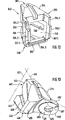
Einem weiteren Teil der Erfindungsgruppe liegt die Aufgabe zugrunde, für Anschlußköpfe von mit Einhänge- bzw. Auflage-Profilen gestalteten Verbindungselementen, wie Horizontal-Tragriegel, eine verbesserte Wand- bzw. Teil-Wand-Gestaltung des Nutzräume aufweisenden Anschlußkopfes zu finden.Another part of the invention group is based on the task of finding an improved wall or partial wall design of the utility rooms having connection head for connection heads of designed with suspension or support profiles connecting elements, such as horizontal support bar.
Zur Lösung dieser Aufgabe sind gemäß einer alternativen Ausgestaltung der Erfindung die folgenden Merkmale vorgesehen: Tragstruktur-Element-Anordnung eines Raumtragwerkes, insbesondere einer Tribüne, eines Podiums oder Gerüstes, das unter Zuhilfenahme von Stielen und wenigstens einen Anschlußkopf aufweisenden stabförmigen Verbindungselementen verwindungssteif ausgebildet ist, mit folgenden Merkmalen:
- – der aus Temperguß-Werkstoff bestehende Anschlußkopf ist mit einem Anschluß-Teil und einem Anlage-Teil gestaltet,
- – der Anlage-Teil hat Anlageflächen aufweisende Anlage-Wandteile zur Anlage an den Stielen,
- – der Anschluß-Teil ist fest mit einem, ein nach oben offenes Profil aufweisenden Stabelement verbunden,
- – der Anschluß-Teil weist eine auf die Füge- und Beanspruchungsverhältnisse sowie das Stabelement angepaßt gestaltete Anschlagfläche zur Anlage des Stabelementes auf,
- – der Anschlußkopf weist einen oberen Kopfteil und einen unteren Kopfteil auf,
- – zwischen diesen ist ein bis zum Anschluß-Teil reichender, zur Anlageseite und den Vertikal-Außen-Flächen offener Schlitz (
360 ) zum Aufstecken auf eine auf dem Stiel angebrachte Lochscheibe ausgebildet, - – im oberen Kopfteil ist eine obere Keilöffung und im unteren Kopfteil ist eine untere Keilöffnung ausgebildet, für einen durch die Keilöffnungen und die Lochscheibe steckbaren, dem Verspannen der zu verbindenden Gerüstelemente dienenden Keil,
- – der Anschlußkopf ist in Umfangsrichtung mit Seiten-Wandteilen und nach oben und unten mit Wandteilen begrenzt, deren die Kräfte übertragende Werkstoff-Bereiche Nutzräume freilassend ausgebildet sind,
- – die Seitenwandteile sind mit Vertikal-Außen-Flächen gebildet, die einen den achten Teil eines Vollkreises einnehmenden Keilwinkel einschließen,
- – der Anlage-Teil des Anschlußkopfes weist ein mit den Anlageflächen der Anlage-Wandteile, mit den Schlitz begrenzenden Schlitzflächen und mit den den Keilwinkel einschließenden Vertikal-Außenflächen gebildeten äußeren Wandflächen begrenztes Volumen auf,
- – der Anschlußkopf weist von den Vertikal-Außen-Flächen, den horizontalen und/oder den schrägen Außen-Flächen ausgehend unter allen Flächenbereichen mit Ausnahme von Übergangsbereichen in Ecken nach innen sich erstreckend im wesentlichen gleiche Wanddicken auf.
- - The existing of malleable cast iron connection head is designed with a connection part and a plant part,
- - The plant part has abutment surfaces having plant wall parts to rest on the stems,
- The connection part is fixedly connected to a rod element having an upwardly open profile,
- The connection part has a stop surface adapted to the conditions of joining and stress as well as the rod element for abutment of the rod element,
- The connection head has an upper head part and a lower head part,
- Between these is a slot extending to the terminal part and open to the plant side and the vertical outer surfaces (
360 ) for attachment to a perforated disc mounted on the handle, - In the upper head part is an upper wedge opening and in the lower head part a lower wedge opening is formed, for a plug-in by the wedge openings and the perforated disc, the bracing of the scaffolding elements to be connected serving,
- - The terminal head is limited in the circumferential direction with side wall parts and upwards and downwards with wall parts, which are designed to release the forces material areas Nutzräume free,
- The side wall parts are formed with vertical outer surfaces which enclose a wedge angle occupying the eighth part of a full circle,
- - The attachment part of the connection head has a with the contact surfaces of the abutment wall parts, with the slot limiting slot surfaces and with the wedge angle enclosing vertical outer surfaces formed outer wall surfaces limited volume,
- - The terminal head has from the vertical outer surfaces, the horizontal and / or oblique outer surfaces starting under all surface areas except for transitional regions in corners extending inwardly substantially equal wall thicknesses.
Dabei kann vorgesehen sein, daß die Vertikal-Außen-Flächen und die zugeordneten Innenwandflächen der oberen und vorzugsweise auch der unteren Seiten-Wandteile in Nachbarschaft der Schlitze im wesentlichen parallel verlaufend mit einer Wanddicke im Bereich des etwa 2,5 bis 4-fachen der Wanddicke des mit dem Anschlußkopf fest verbunddenen Stabelementes gestaltet sind.It can be provided that the vertical outer surfaces and the associated inner wall surfaces of the upper and preferably also the lower side wall portions in the vicinity of the slots substantially parallel to a wall thickness in the range of about 2.5 to 4 times the wall thickness are designed with the connection head firmly connected to the rod element.
Dadurch ist das Verbindungselement mit Gerüstelement-Teilen gebildet, die hinsichtlich der insbesondere bei Baugerüsten auftretenden statischen und dynamischen Beanspruchungen in vorteilhafter Weise aufeinander abgestimmt gestaltet sind.As a result, the connecting element is formed with scaffolding element parts, which are designed to be coordinated with one another in an advantageous manner with regard to the static and dynamic stresses occurring, in particular, in scaffolding.
Ferner kann vorgesehen sein, daß das Stabelement U-profilförmig ausgebildet ist. Dadurch eignet sich das mit Anschlußköpfen versehene Verbindungselement insbesondere als Horizontal-Tragriegel zur Auflage von mit Klauen versehenen Gerüstböden. Furthermore, it can be provided that the rod element is U-shaped profile. As a result, the connecting element provided with connection heads is suitable, in particular, as a horizontal support bar for supporting scaffolding floors provided with claws.
Ferner kann vorgesehen sein, daß der Anschluß-Teil des Anschlußkopfes mit einem nach oben offenen U-Profil gebildet ist. Dies erleichtert die Montage und ermöglicht eine bessere Zugänglichkeit beim Verschweißen des Anschlußkopfes mit dem Profil-Stabelement.Furthermore, it can be provided that the connection part of the connection head is formed with an upwardly open U-profile. This facilitates assembly and allows better accessibility when welding the connection head with the profile rod element.
Ferner kann vorgesehen sein, daß der Anschluß-Teil mit sich über die Anschlagfläche nach außen erstreckenden Zentrierlappen gestaltet ist, wobei vorzugsweise zwei horizontal beabstandete Zentrierlappen vorgesehen sind, deren Außenflächen einen Abstand voneinander aufweisen, der geringfügig kleiner ist als der Abstand zwischen den einander gegenüberliegenden Innenflächen der Seitenschenkel des U-profilförmigen Stabelementes. Alternativ hierzu oder zusammen mit den vorstehenden Maßnahmen kann vorgesehen sein, daß der Anschluß-Teil mit einem sich geringfügig über die Anschlagfläche erhebenden umlaufenden Zentrierkragen gestaltet ist. Diese Maßnahmen ermöglichen eine leichte und paßgenaue Montage des mit dem Anschlußkopf fest zu verbindenen Profilstabelementes.Furthermore, it can be provided that the connection part is designed with over the stop surface outwardly extending centering tabs, preferably two horizontally spaced centering tabs are provided, the outer surfaces spaced from each other, which is slightly smaller than the distance between the opposite inner surfaces the side leg of the U-shaped rod element. Alternatively, or together with the above measures can be provided that the connection part is designed with a slightly rising above the stop surface revolving centering collar. These measures allow easy and accurate installation of firmly connected to the connection head profiled rod element.
Einen weiteren Teil der Erfindungsgruppe liegt die Aufgabe zugrunde, für Anschlußköpfe von gelenkig gestalteten Verbindungselementen, wie Diagonalstäben, eine verbesserte Wand- bzw. Teil-Wand-Gestaltung des Nutzräume aufweisenden Ansch1ußkopfes zu finden.Another part of the invention group is the object of finding an improved wall or partial wall design of the utility rooms Anschlußkopfes for connection heads of articulated connecting elements, such as diagonal bars.
Zur Lösung dieser Aufgabe sind gemäß einer alternativen Ausgestaltung der Erfindung die folgenden Merkmale vorgesehen:
Tragstruktur-Element-Anordnung eines Raumtragwerkes, insbesondere einer Tribune, eines Podiums oder Gerüstes, das unter Zuhilfenahme von Stielen und wenigstens einen Anschlußkopf aufweisenden stabförmigen Verbindungselementen verwindungssteif ausgebildet ist, mit folgenden Merkmalen:
- – der aus Temperguß-Werkstoff bestehende Anschlußkopf ist mit einem Anschluß-Teil und einem Anlage-Teil gestaltet,
- – der Anlage-Teil hat Anlageflächen aufweisende Anlage-Wandteile zur Anlage an den Stielen,
- – der Anschluß-Teil weist einen Gelenk-Teil auf,
- – der Gelenk-Teil ist verschwenkbar mit einem Stabelement, insbesondere einem Diagonalstab verbunden,
- – der Anschlußkopf weist einen oberen Kopfteil und einen unteren Kopfteil auf,
- – zwischen diesen ist ein bis zum Anschluß-Teil reichender, zur Anlageseite und den Vertikal-Außen-Flächen offener Schlitz zum Aufstecken auf eine auf dem Stiel angebrachte Lochscheibe ausgebildet,
- – im oberen Kopfteil ist eine obere Keilöffung und im unteren Kopfteil ist eine untere Keilöffnung ausgebildet, für einen durch die Keilöffnungen und die Lochscheibe steckbaren, dem Verspannen der zu verbindenden Gerüstelemente dienenden Keil,
- – der Anschlußkopf ist in Umfangsrichtung mit Seiten-Wandteilen und nach oben und unten mit Wandteilen begrenzt, deren die Kräfte übertragende Werkstoff-Bereiche Nutzräume freilassend ausgebildet sind,
- – die Seitenwandteile sind mit Vertikal-Außen-Flächen gebildet, die einen den achten Teil eines Vollkreises einnehmenden Keilwinkel einschließen,
- – der Anlage-Teil des Anschlußkopfes weist ein mit den Anlageflächen der Anlage-Wandteile, mit den Schlitz begrenzenden Schlitzflächen und mit den den Keilwinkel einschließenden Vertikal-Außenflächen gebildeten äußeren Wandflächen begrenztes Volumen auf,
- – der Anschlußkopf weist von den Vertikal-Außen-Flächen, den horizontalen und/oder den schrägen Außen-Flächen ausgehend unter allen Flächenbereichen mit Ausnahme von Übergangsbereichen in Ecken nach innen sich erstreckend im wesentlichen gleiche Wanddicken auf.
Support structure-element arrangement of a space structure, in particular a grandstand, a podium or scaffold, which is torsionally rigid with the aid of stems and at least one connecting head having rod-shaped connecting elements, with the following features:
- - The existing of malleable cast iron connection head is designed with a connection part and a plant part,
- - The plant part has abutment surfaces having plant wall parts to rest on the stems,
- The connection part has a joint part,
- - The hinge part is pivotally connected to a rod element, in particular a diagonal bar,
- The connection head has an upper head part and a lower head part,
- - Between these is a reaching to the terminal part, open to the plant side and the vertical outer surfaces open slot for attachment to a mounted on the stem perforated disc,
- In the upper head part is an upper wedge opening and in the lower head part a lower wedge opening is formed, for a plug-in by the wedge openings and the perforated disc, the bracing of the scaffolding elements to be connected serving,
- - The terminal head is limited in the circumferential direction with side wall parts and upwards and downwards with wall parts, which are designed to release the forces material areas Nutzräume free,
- The side wall parts are formed with vertical outer surfaces which enclose a wedge angle occupying the eighth part of a full circle,
- - The attachment part of the connection head has a with the contact surfaces of the abutment wall parts, with the slot limiting slot surfaces and with the wedge angle enclosing vertical outer surfaces formed outer wall surfaces limited volume,
- - The terminal head has starting from the vertical outer surfaces, the horizontal and / or oblique outer surfaces starting under all surface areas except for transition areas in corners inwardly substantially equal wall thicknesses.
Dabei kann vorgesehen sein, den Gelenk-Teil unter einem Winkel von 135° zu einer zur Stielachse weisenden Mittellinie des Anschlußkopfes anzuordnen. Dies ermöglicht insbesondere dann, wenn vier rechtwinklig zueinander angeordnete Durchbrüche der Lochscheiben mit horizontalen Stabelementen, wie Horizontal-Tragriegeln, Längsriegeln, Querriegeln oder Gitterträgern in Anspruch genommen sind, den Anschluß von das Raumtragwerk zusätzlich versteifenden Diagonalverstrebungen.It can be provided to arrange the joint part at an angle of 135 ° to a shaft axis pointing to the center line of the connection head. This makes it possible, in particular, if four apertures of the perforated disks arranged at right angles to one another are used with horizontal bar elements, such as horizontal bars, longitudinal bars, cross bars or lattice girders, the connection of diagonal struts additionally stiffening the space structure.
Ferner kann vorgesehen sein, daß der Gelenk-Teil mit einer Gelenklasche ausgebildet ist, die vorzugsweise in Teilbereichen parallele Außenflächen sowie vorzugsweise eine Bohrung zur Aufnahme eines mit dem Stabelement verbindbaren zylinderförmigen Lager- und Anlenkelementes aufweist. Dies ermöglicht eine einfache, sichere und raumsparende Befestigung des Diagonalstabes an dem Anschlußkopf und erlaubt ein ungehindertes Verschwenken der beiden Bauelemente.Furthermore, it can be provided that the joint part is formed with a joint flap, which preferably in partial areas parallel outer surfaces and preferably has a bore for receiving a connectable to the rod member cylindrical bearing and articulation element. This allows a simple, safe and space-saving attachment of the diagonal bar to the connection head and allows unimpeded pivoting of the two components.
Ferner kann vorgesehen sein, daß die Gelenklasche an ihrem vom Anschluß-Teil wegweisenden Ende mit einem Radius abgerundet gestaltet ist. Dies vermeidet ggf. störende Eckbereiche und ermöglicht eine weitere Gewichtsreduktion.Furthermore, it can be provided that the joint flap is designed rounded at its end facing away from the connection part end with a radius. This avoids possibly disturbing corner areas and allows a further weight reduction.
Weitere Einzelheiten, Vorteile, Merkmale und Gesichtspunkte der Erfindung ergeben sich aus dem nachfolgenden anhand der Zeichnungen abgehandelten Beschreibungsteil. Further details, advantages, features and aspects of the invention will become apparent from the following with reference to the drawings dealt with part description.
Ein Ausführungsbeispiel der Erfindung wird nachfolgend anhand der Zeichnungen näher erläutert. Es zeigtAn embodiment of the invention will be explained in more detail with reference to the drawings. It shows
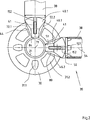
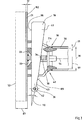
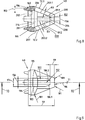
Das Gerüst
Gerüstelemente bzw. Verbindungselemente
Wie die weiteren Zeichnungen zeigen, sind die Verbindungselemente
Die Keile
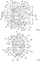
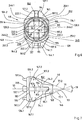
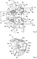
Jeder Anschlußkopf
Zwischen den oberen Seiten-Wandteilen
Der in einer parallel zur Vertikal-Symmetrie-Ebene
Die Schlitzbreite
Die oberen sowie die unteren Seiten-Wandteile
Die oberen Vertikal-Außen-Flächen
Die oberen Seiten-Wandteile
Der obere bzw. untere Seiten-Wandteil
Die Bogenlänge
Der obere und der untere Anlage-Wandteil
Die Anlage-Wandteile
Der obere und der untere Seiten-Wandteil
Die untere dreieckförmige Übergangsfläche
Der Ober-Wandteil
Im Ober-Wandteil
Der obere Übergangs-Wandteil
Der Unter-Wandteil
Der untere Horizontal-Wandteil
Alle Übergänge zwischen den Seiten-Wandteilen
Dieser weist eine mit dem Keil-Aufnahmeraum
Der Anschluß-Teil
Zur Zentrierung des Rohres
Der Anschlußkopf
Die Trapez-Basis
Wie insbesondere aus
Die Anschlußköpfe
Das Volumen der Anschlußköpfe
Geht man zunächst von einer Erhöhung des spezifischen Volumens des Anlage-Teils
Bei den Anschlußköpfen
Der Anschluß-Teil
Die beiden seitlichen Schenkel
In
Die vorteilhafte Gestaltung der Außenflächen der Anschlußköpfe
Nachfolgend wird ein wichtiger Teil der Beschreibung wiedergegeben:
Die Tragstruktur-Element-Anordnung ist mit dem Verbindungselement (
The support structure element arrangement is connected to the connecting element (
BezugszeichenlisteLIST OF REFERENCE NUMBERS
- 2020
- Gerüstframework
- 2121
- Stielstalk
- 2222
- HorizontalstabHorizontal bar
- 2323
- Diagonalstabdiagonal bar
- 2424
- Horizontal-TragriegelHorizontal supporting bars
- 2525
- Gerüstbodenframework floor
- 2626
- EinhängeklaueEinhängeklaue
- 2727
- Fußfoot
- 2828
- Abstanddistance
- 2929
-
Wanddicke von
38 Wall thickness of38 - 3030
- Lochscheibeperforated disc
- 3131
- Lochhole
- 31.131.1
- Lochhole
- 31.231.2
- Lochhole
- 3232
-
Wanddicke von
21 Wall thickness of21 - 3333
- SchweißnahtWeld
- 3434
-
Anschlagfläche von
30 Stop surface of30 - 3535
- Verbindungselementconnecting element
- 3636
-
unteres Ende von
41 lower end of41 - 3737
- Geländerrailing
- 3838
- Rohrpipe
- 3939
-
Außendurchmesser von
38 Outside diameter of38 - 4040
- Anschlußkopfconnecting head
- 40.140.1
- Anschlußkopfconnecting head
- 40.240.2
- Anschlußkopfconnecting head
- 4141
- Keilwedge
- 4242
- Nietrivet
- 4343
- Ausnehmungrecess
- 4444
- oberer Kopfteilupper headboard
- 4545
- unterer Kopfteillower headboard
- 4646
- oberer Seiten-Wandteilupper side wall part
- 46.146.1
- oberer Seiten-Wandteilupper side wall part
- 46.246.2
- 4747
- unterer Seiten-Wandteillower side wall part
- 47.147.1
- unterer Seiten-Wandteillower side wall part
- 47.247.2
- 4848
- Ober-WandteilOber-wall part
- 4949
- Unter-WandteilUnder-wall part
- 5050
-
Anschluß-Teil von
40 Connection part of40 - 5151
- oberer Anlage-WandteilUpper plant wall part
- 5252
- unterer Anlage-Wandteillower plant wall part
- 5353
- Stielachsestem axis
- 5454
- Rohrachsepipe axis
- 5555
- Vertikal-Symmetrie-EbeneVertical plane of symmetry
- 5656
-
Höhe von
44 Height of44 - 5757
-
Höhe von
45 Height of45 - 5858
-
Höhe von
40 Height of40 - 5959
-
Tiefe von
40 Depth of40 - 6060
- Schlitzslot
- 6161
- obere Schlitzflächeupper slot area
- 61.161.1
- obere Schlitzflächeupper slot area
- 61.261.2
- 6262
- untere Schlitzflächelower slot area
- 62.162.1
- untere Schlitzflächelower slot area
- 62.262.2
- 6363
- vertikale Schlitzflächevertical slot area
- 63.163.1
- vertikale Schlitzflächevertical slot area
- 63.263.2
- 6464
- Radiusradius
- 6565
- Abstanddistance
- 6666
- Anlageseiteinvestment side
- 6767
-
oberes Ende von
84 upper end of84 - 6868
- Schlitzbreiteslot width
- 6969
-
Dicke von
30 Thickness of30 - 7070
-
oberes Einschlag-Ende von
41 upper turn-off end of41 - 7171
- Stiel- und ScheibenzentrumStem and disc center
- 7272
- obere Vertikal-Außen-Flächeupper vertical outer surface
- 72.172.1
- obere Vertikal-Außen-Flächeupper vertical outer surface
- 72.272.2
- 7373
- untere Vertikal-Außen-Flächelower vertical outer surface
- 73.173.1
- untere vertikal-Außen-Flächelower vertical-outer surface
- 73.273.2
- 7474
- obere Übergangsflächeupper transition surface
- 74.174.1
- obere Übergangsflächeupper transition surface
- 74.274.2
- 7575
- Abstanddistance
- 7676
- untere Übergangsflächelower transition surface
- 76.176.1
- untere Übergangsflächelower transition surface
- 76.276.2
- 77.177.1
- Ebenelevel
- 77.277.2
- Ebenelevel
- 7878
-
Anschlußende von
52 Connection end of52 - 7979
- Keilwinkelwedge angle
- 8080
-
Anlage-Teil von
40 Plant part of40 - 8181
- obere Innenwandflächeupper inner wall surface
- 81.181.1
- obere Innenwandflächeupper inner wall surface
- 81.281.2
- 8282
- untere Innenwandflächelower inner wall surface
- 82.182.1
- untere Innenwandflächelower inner wall surface
- 82.282.2
- 8383
- Wanddickewall thickness
- 8484
- obere Anlageflächeupper contact surface
- 8585
- untere Anlageflächelower contact surface
- 8686
-
Außenradius von
84 bzw.85 Outer radius of84 respectively.85 - 8787
- Stiel-AußenradiusStalk outer radius
- 8888
-
unteres Ende von
85 lower end of85 - 8989
-
Innendurchmesser von
38 Inside diameter of38 - 9090
- Horizontal-EbeneHorizontal level
- 9191
-
Breite von
84 ,85 Width of84 .85 - 9292
-
Höhe von
84 ,85 Height of84 .85 - 9393
-
Bogenlänge von
84 ,85 Arc length of84 .85 - 9494
- Durchbrechungperforation
- 9595
- Durchbrechungperforation
- 9696
- vertikale Keil-Anschlagflächevertical wedge stop surface
- 96.196.1
- vertikale Keil-Anschlagflächevertical wedge stop surface
- 96.296.2
- 96.396.3
- 96.496.4
- 9797
- Ebenelevel
- 9898
-
vordere Anschlagkante von
41 front stop edge of41 - 99 99
-
Wanddicke von
50 ,51 Wall thickness of50 .51 - 100100
- Einführ-WandteilInsertion wall part
- 101101
- Einführ-WandteilInsertion wall part
- 102102
- Winkelangle
- 103103
- Winkelangle
- 104104
-
Schrägfläche von
100 Inclined surface of100 - 105105
-
Schrägfläche von
101 Inclined surface of101 - 106106
- Ausnehmungrecess
- 107107
-
Breite von
94 ,95 Width of94 .95 - 108108
-
Höhe von
94 ,95 Height of94 .95 - 109109
-
hintere Anlagekante von
41 rear abutment edge of41 - 110110
- Keil-WinkelWedge angle
- 111111
- KreissegmentflächeCircular segment surface
- 112112
-
Bogen von
111 Bow of111 - 113113
-
Sehne von
111 Tendon of111 - 114114
- oberer Schnittpunktupper intersection
- 115115
- unterer Schnittpunktlower intersection
- 117117
-
Hypotenuse von
74 Hypotenuse of74 - 118118
- Eckecorner
- 119119
- Kathetecathetus
- 121121
- ÜbergangskanteTransition edge
- 122122
-
oberer Horizontal-Wandteil v.
48 upper horizontal wall part v.48 - 123123
-
Länge von
121 length of121 - 124124
- Kathetecathetus
- 126126
- ÜbergangskanteTransition edge
- 127127
- oberer Übergangs-WandteilUpper transition wall part
- 127.1127.1
- oberer Übergangs-WandteilUpper transition wall part
- 127.2127.2
- 128128
- hinterer oberer Übergangs-Wandteilrear upper transition wall part
- 128.1128.1
- hinterer oberer Übergangs-Wandteilrear upper transition wall part
- 128.2128.2
- 129129
- hinterer unterer Übergangs-Wandteilrear lower transition wall part
- 131131
-
Hypotenuse von
74 Hypotenuse of74 - 132132
- Schnittpunktintersection
- 133133
- Abstanddistance
- 134.1134.1
-
Außenfläche von
128 Outer surface of128 - 134.2134.2
- 136136
- Abstanddistance
- 137137
- untere Keilöffnunglower wedge opening
- 138138
- Kathetecathetus
- 139139
- Schnittpunktintersection
- 140140
-
Außenfläche von
129 Outer surface of129 - 141141
- unterer Übergangs-Wandteillower transition wall part
- 142142
- Kathetecathetus
- 143143
- untere Übergangskantelower transition edge
- 144144
-
Außenfläche von
141 Outer surface of141 - 144.1144.1
-
Außenfläche von
141 Outer surface of141 - 144.2144.2
- 146146
-
Außenfläche von
122 Outer surface of122 - 147147
-
Außenfläche von
127 Outer surface of127 - 147.1147.1
-
Außenfläche von
127 Outer surface of127 - 147.2147.2
- 148148
-
Innenfläche von
122 Inside surface of122 - 149149
-
Innenfläche von
127 Inside surface of127 - 150150
-
Wanddicke von
48 Wall thickness of48 - 151151
- Wanddickewall thickness
- 152152
- obere Keilöffnungupper wedge opening
- 153153
- Abstanddistance
- 154154
- Keil-StützflächeWedge support surface
- 155155
- Keil-StützflächeWedge support surface
- 156156
-
Breite von
96.1 Width of96.1 - 157157
- Keildickewedge thickness
- 158158
- Abstanddistance
- 159159
- Schweißnahtbereichweld area
- 160160
- Ringwulsttorus
- 161161
- Oberflächesurface
- 162162
- Stiel-AußenflächeStem outer surface
- 171171
-
unterer Horizontal-Wandteil von
49 lower horizontal wall part of49 - 173173
-
Länge von
137 length of137 - 174174
-
Breite von
137 Width of137 - 176176
-
Außenfläche von
171 Outer surface of171 - 177177
-
Außenfläche von
141 Outer surface of141 - 178178
-
Innenfläche von
171 Inside surface of171 - 179179
-
Innenfläche von
141 Inside surface of141 - 180180
-
Wanddicke von
49 Wall thickness of49 - 181181
- Radiusradius
- 182182
- obere Öffnungskanteupper opening edge
- 183183
- untere Öffnungskantelower opening edge
- 184184
- Wanddickewall thickness
- 186.1186.1
- Schrägflächesloping surface
- 186.2186.2
- Schrägflächesloping surface
- 193193
- Dickethickness
- 194194
-
Ende von
160 End of160 - 195195
- Schräg-RingflächeOblique annular surface
- 196196
- Anschlagflächestop surface
- 197197
- Zentrierlappencentering tabs
- 197.1197.1
- Zentrierlappencentering tabs
- 197.2197.2
- 197.3197.3
- 197.4197.4
- 198198
-
Außendurchmesser von
195 Outside diameter of195 - 199199
-
Innendurchmesser von
195 Inside diameter of195 - 200200
- KeilaufnahmeraumWedge housing space
- 201201
- Trapez-BasisTrapezoid base
- 202202
- Innenflächepalm
- 203.1203.1
- Trapez-SeiteTrapezoidal side
- 203.2203.2
- 204204
- Trapez-GrundlinieTrapezoidal baseline
- 206206
- Trapez-EckeTrapezoid corner
- 207207
- Trapez-EckeTrapezoid corner
- 208208
- Trapez-EckeTrapezoid corner
- 209209
- Trapez-EckeTrapezoid corner
- 211211
-
Breite von
195 Width of195 - 213213
- EndeThe End
- 214214
- Stützstegsupporting web
- 216216
-
Querschnitt von
214 Cross section of214 - 217217
- Stützsteg-TeilSupporting web-part
- 218218
- Neigungswinkeltilt angle
- 219219
-
Spitze von
217 Tip of217 - 221221
- Abstanddistance
- 222.1222.1
-
Außenfläche von
197.1 Outer surface of197.1 - 222.2222.2
-
Außenfläche von
197.2 Outer surface of197.2 - 222.3222.3
-
Außenfläche von
197.3 Outer surface of197.3 - 222.4222.4
-
Außenfläche von
197.4 Outer surface of197.4 - 223223
- Durchmesserdiameter
- 224224
-
Innendurchmesser von
38 Inside diameter of38 - 226226
- Innenraum-begrenzungsflächeInterior limitation area
- 230230
- vertiefter Wandflächenbereichrecessed wall surface area
- 230.1230.1
-
vertiefter Wandflächenbereich von
72.1 Recessed wall surface area of72.1 - 230.2230.2
-
vertiefter Wandflächenbereich von
72.2 Recessed wall surface area of72.2 - 231231
- vertiefter Wandflächenbereichrecessed wall surface area
- 231.1231.1
-
vertiefter Wandflächenbereich von
73.1 Recessed wall surface area of73.1 - 231.2231.2
-
vertiefter Wandflächenbereich von
73.2 Recessed wall surface area of73.2 - 232232
- Abstanddistance
- 240240
- Vertikalebenevertical plane
- 245245
- Öffnungopening
- 246246
-
Öffnungskante von
245 Opening edge of245 - 246.1246.1
-
Öffnungskante von
245 Opening edge of245 - 246.2246.2
- 246.3246.3
- 246.3246.3
- 247247
- ÖffnungsdurchmesserOpening diameter
- 251251
-
Öffnungskante von
245 Opening edge of245 - 251.1251.1
-
Öffnungskante von
245 Opening edge of245 - 251.2251.2
- 251.3251.3
- 251.4251.4
- 252252
- ÖffnungsdurchmesserOpening diameter
- 340340
- Anschlußkopfconnecting head
- 344344
- oberer Kopfteilupper headboard
- 345345
- unterer Kopfteillower headboard
- 350350
- Anschluß-TeilConnecting partial
- 353353
- U-ProfilU-profile
- 354.1354.1
-
Schenkel von
353 Thighs of353 - 354.2354.2
- 354.3354.3
- 360360
- Schlitzslot
- 380380
- Anlage-TeilPlant part
- 390390
- Zentrierkragencentering collar
- 396396
- Anschlagflächestop surface
- 397397
- Zentrierlappencentering tabs
- 397.1397.1
- Zentrierlappencentering tabs
- 397.2397.2
- 398.1398.1
-
Außenfläche von
397.1 Outer surface of397.1 - 398.2398.2
-
Außenfläche von
397.2 Outer surface of397.2 - 440440
- Anschlußkopfconnecting head
- 444444
- oberer Kopfteilupper headboard
- 445445
- unterer Kopfteillower headboard
- 450450
- Anschluß-TeilConnecting partial
- 453453
- Stielachsestem axis
- 455455
- Mittelliniecenter line
- 460460
- Schlitzslot
- 475475
- Winkelangle
- 480480
- Anlage-TeilPlant part
- 485485
- Vertikal-WandteilVertical wall portion
- 490490
- Gelenklaschejoint plate
- 491491
-
Außenfläche von
490 Outer surface of490 - 492492
-
Außenfläche von
490 Outer surface of490 - 495495
- Bohrungdrilling
- 496496
- EndeThe End
- 497497
- Radiusradius
Claims (14)
Priority Applications (1)
| Application Number | Priority Date | Filing Date | Title |
|---|---|---|---|
| DE1998106093 DE19806093B4 (en) | 1998-02-14 | 1998-02-14 | Support structure element arrangement of a space structure |
Applications Claiming Priority (1)
| Application Number | Priority Date | Filing Date | Title |
|---|---|---|---|
| DE1998106093 DE19806093B4 (en) | 1998-02-14 | 1998-02-14 | Support structure element arrangement of a space structure |
Publications (2)
| Publication Number | Publication Date |
|---|---|
| DE19806093A1 DE19806093A1 (en) | 1999-08-19 |
| DE19806093B4 true DE19806093B4 (en) | 2012-07-05 |
Family
ID=7857734
Family Applications (1)
| Application Number | Title | Priority Date | Filing Date |
|---|---|---|---|
| DE1998106093 Expired - Lifetime DE19806093B4 (en) | 1998-02-14 | 1998-02-14 | Support structure element arrangement of a space structure |
Country Status (1)
| Country | Link |
|---|---|
| DE (1) | DE19806093B4 (en) |
Families Citing this family (9)
| Publication number | Priority date | Publication date | Assignee | Title |
|---|---|---|---|---|
| EP1179650B1 (en) * | 2000-03-21 | 2003-12-17 | Ulma, C Y E, S. Coop. | Improved stage |
| ATE414829T1 (en) * | 2000-04-04 | 2008-12-15 | Pieter Wouter Booysen | FRAMEWORK |
| GB2362421B (en) * | 2000-04-14 | 2004-01-21 | Kwikform Uk Ltd | Improvements to builders scaffolding |
| DE10203949A1 (en) * | 2002-02-01 | 2003-08-21 | Helmut Kroenert | Multi-purpose sports and leisure area has free standing frame assembly as base housing sports floor and with levelling devices and strips to define useful surface area |
| DE102011001796A1 (en) | 2011-04-05 | 2012-10-11 | Wilhelm Layher Verwaltungs-Gmbh | scaffolding post |
| WO2012163340A1 (en) | 2011-06-01 | 2012-12-06 | Wilhelm Layher Verwaltungs-Gmbh | Arrangement of a scaffolding component and of a vertical scaffolding element |
| DE102012018695B4 (en) * | 2012-09-21 | 2015-05-21 | Pyramid Computer Gmbh | Kit with two, adjacent housing sides adjacent to each other housings |
| IT201600108828A1 (en) * | 2016-10-27 | 2018-04-27 | Amadio & C S P A | SYSTEM FOR CONNECTING VERTICAL UPRIGHTS AND CURRENTS SUPPORTING A FOOTBALL FLOOR FOR A CRAFTING |
| CN114991010B (en) * | 2022-05-11 | 2023-05-16 | 山东交通学院 | Bottom stabilizing device for disc buckle type support after installation |
Citations (5)
| Publication number | Priority date | Publication date | Assignee | Title |
|---|---|---|---|---|
| DE2625455A1 (en) * | 1976-06-05 | 1977-12-22 | Scheffel & Rueter | Demountable lattice frame structure connection - has traverse ends inserted in nodal plate slots with flank cutouts |
| DE3110637A1 (en) * | 1980-03-27 | 1982-02-18 | Select Etem S.A., 47400 Tonneins | CONNECTING NODE FOR STRUCTURAL STRUCTURES |
| DE3702057A1 (en) * | 1987-01-24 | 1988-08-04 | Langer Ruth Geb Layher | SCAFFOLDED WITH CONNECTING DEVICES |
| EP0402814A1 (en) * | 1989-06-12 | 1990-12-19 | Langer, Ruth, geb. Layher | Support device for load-bearing elements in grandstands or scaffoldings |
| DE3934857A1 (en) * | 1989-10-19 | 1991-04-25 | Langer Ruth Geb Layher | CONNECTING HEAD FOR SCAFFOLDING |
-
1998
- 1998-02-14 DE DE1998106093 patent/DE19806093B4/en not_active Expired - Lifetime
Patent Citations (5)
| Publication number | Priority date | Publication date | Assignee | Title |
|---|---|---|---|---|
| DE2625455A1 (en) * | 1976-06-05 | 1977-12-22 | Scheffel & Rueter | Demountable lattice frame structure connection - has traverse ends inserted in nodal plate slots with flank cutouts |
| DE3110637A1 (en) * | 1980-03-27 | 1982-02-18 | Select Etem S.A., 47400 Tonneins | CONNECTING NODE FOR STRUCTURAL STRUCTURES |
| DE3702057A1 (en) * | 1987-01-24 | 1988-08-04 | Langer Ruth Geb Layher | SCAFFOLDED WITH CONNECTING DEVICES |
| EP0402814A1 (en) * | 1989-06-12 | 1990-12-19 | Langer, Ruth, geb. Layher | Support device for load-bearing elements in grandstands or scaffoldings |
| DE3934857A1 (en) * | 1989-10-19 | 1991-04-25 | Langer Ruth Geb Layher | CONNECTING HEAD FOR SCAFFOLDING |
Also Published As
| Publication number | Publication date |
|---|---|
| DE19806093A1 (en) | 1999-08-19 |
Similar Documents
| Publication | Publication Date | Title |
|---|---|---|
| EP2134908B1 (en) | Vertical frame intended for the construction of a frame stanchion, a supporting frame and/or a supporting frame tower | |
| EP1452667B1 (en) | System of elements of supporting structure of a three-dimensional framework | |
| DE2704398C3 (en) | Framework that can be assembled from uprights and bars | |
| DE102012104697A1 (en) | Arrangement of a scaffolding component and a vertical scaffolding element | |
| WO2008043339A1 (en) | Vertical frame made of metal | |
| EP2390439B1 (en) | Module frame with rigid adjoining tubular cross bar connections | |
| DE2554855B2 (en) | Coupling piece for scaffolding | |
| DE3147081A1 (en) | Supporting framework for concrete shutterings | |
| WO2016138889A1 (en) | Truss frame, modular truss girder and bridging and/or support construction | |
| DE19806093B4 (en) | Support structure element arrangement of a space structure | |
| DE3049971C2 (en) | ||
| EP0512428B1 (en) | Working platform for walls or shuttering | |
| DE3504188A1 (en) | Diagonal strut for scaffoldings | |
| EP0361250B1 (en) | Coupling for scaffold railings | |
| DE3922722C2 (en) | ||
| DE29825219U1 (en) | Scaffolding or stage support structure | |
| DE29924873U1 (en) | Scaffolding or stage support structure | |
| DE2509064C3 (en) | Dismountable ladder | |
| DE3513553A1 (en) | Shelf unit which can be dismantled, in particular shelf unit for pallets | |
| EP0736648A1 (en) | Scaffold | |
| DE3808145A1 (en) | REINFORCED HANGER FOR CABLES | |
| CH696591A5 (en) | Mobile fall arrest safety device for construction sites on flat roofs. | |
| DE3022439A1 (en) | Scaffolding vertical bar and strut connectors - are double sockets with bar ends inserted and have external strut attachments | |
| DE4316976A1 (en) | Scaffolding platform | |
| CH716839A1 (en) | Pipe connection structure and furniture kit. |
Legal Events
| Date | Code | Title | Description |
|---|---|---|---|
| OM8 | Search report available as to paragraph 43 lit. 1 sentence 1 patent law | ||
| 8181 | Inventor (new situation) |
Free format text: ANTRAG AUF NICHTNENNUNG |
|
| 8110 | Request for examination paragraph 44 | ||
| 8127 | New person/name/address of the applicant |
Owner name: WILHELM LAYHER VERWALTUNGS-GMBH, 74363 GUEGLINGEN, |
|
| R019 | Grant decision by federal patent court | ||
| R020 | Patent grant now final |
Effective date: 20121006 |
|
| R008 | Case pending at federal patent court | ||
| R039 | Revocation action filed |
Effective date: 20140226 |
|
| R020 | Patent grant now final | ||
| R040 | Withdrawal/refusal of revocation action now final | ||
| R040 | Withdrawal/refusal of revocation action now final |
Effective date: 20150108 |
|
| R071 | Expiry of right |