EP0421321B1 - Einrichtung zur Befestigung einer sanitären Trockenarmatur - Google Patents
Einrichtung zur Befestigung einer sanitären Trockenarmatur Download PDFInfo
- Publication number
- EP0421321B1 EP0421321B1 EP90118801A EP90118801A EP0421321B1 EP 0421321 B1 EP0421321 B1 EP 0421321B1 EP 90118801 A EP90118801 A EP 90118801A EP 90118801 A EP90118801 A EP 90118801A EP 0421321 B1 EP0421321 B1 EP 0421321B1
- Authority
- EP
- European Patent Office
- Prior art keywords
- sliding block
- wall
- opening
- mounting part
- fitting
- Prior art date
- Legal status (The legal status is an assumption and is not a legal conclusion. Google has not performed a legal analysis and makes no representation as to the accuracy of the status listed.)
- Expired - Lifetime
Links
- 238000006073 displacement reaction Methods 0.000 claims description 7
- 230000009471 action Effects 0.000 claims description 4
- 230000005489 elastic deformation Effects 0.000 description 4
- 230000000295 complement effect Effects 0.000 description 3
- 230000006835 compression Effects 0.000 description 3
- 238000007906 compression Methods 0.000 description 3
- 230000008901 benefit Effects 0.000 description 2
- 238000001035 drying Methods 0.000 description 2
- 230000000694 effects Effects 0.000 description 2
- 238000004519 manufacturing process Methods 0.000 description 2
- 239000002184 metal Substances 0.000 description 2
- 230000008859 change Effects 0.000 description 1
- 238000006243 chemical reaction Methods 0.000 description 1
- 238000010276 construction Methods 0.000 description 1
- 238000010168 coupling process Methods 0.000 description 1
- 238000005859 coupling reaction Methods 0.000 description 1
- 239000011521 glass Substances 0.000 description 1
- 238000000034 method Methods 0.000 description 1
- 230000008569 process Effects 0.000 description 1
- 230000007704 transition Effects 0.000 description 1
- XLYOFNOQVPJJNP-UHFFFAOYSA-N water Substances O XLYOFNOQVPJJNP-UHFFFAOYSA-N 0.000 description 1
Images

Classifications
-
- F—MECHANICAL ENGINEERING; LIGHTING; HEATING; WEAPONS; BLASTING
- F16—ENGINEERING ELEMENTS AND UNITS; GENERAL MEASURES FOR PRODUCING AND MAINTAINING EFFECTIVE FUNCTIONING OF MACHINES OR INSTALLATIONS; THERMAL INSULATION IN GENERAL
- F16B—DEVICES FOR FASTENING OR SECURING CONSTRUCTIONAL ELEMENTS OR MACHINE PARTS TOGETHER, e.g. NAILS, BOLTS, CIRCLIPS, CLAMPS, CLIPS OR WEDGES; JOINTS OR JOINTING
- F16B7/00—Connections of rods or tubes, e.g. of non-circular section, mutually, including resilient connections
- F16B7/04—Clamping or clipping connections
- F16B7/044—Clamping or clipping connections for rods or tubes being in angled relationship
- F16B7/0446—Clamping or clipping connections for rods or tubes being in angled relationship for tubes using the innerside thereof
- F16B7/0453—Clamping or clipping connections for rods or tubes being in angled relationship for tubes using the innerside thereof the tubes being drawn towards each other
-
- A—HUMAN NECESSITIES
- A47—FURNITURE; DOMESTIC ARTICLES OR APPLIANCES; COFFEE MILLS; SPICE MILLS; SUCTION CLEANERS IN GENERAL
- A47K—SANITARY EQUIPMENT NOT OTHERWISE PROVIDED FOR; TOILET ACCESSORIES
- A47K10/00—Body-drying implements; Toilet paper; Holders therefor
- A47K10/04—Towel racks; Towel rails; Towel rods; Towel rolls, e.g. rotatable
- A47K10/10—Towel racks; Towel rails; Towel rods; Towel rolls, e.g. rotatable characterised by being mounted on cabinets, walls, doors, or the like
-
- A—HUMAN NECESSITIES
- A47—FURNITURE; DOMESTIC ARTICLES OR APPLIANCES; COFFEE MILLS; SPICE MILLS; SUCTION CLEANERS IN GENERAL
- A47K—SANITARY EQUIPMENT NOT OTHERWISE PROVIDED FOR; TOILET ACCESSORIES
- A47K2201/00—Details of connections of bathroom accessories, e.g. fixing soap or towel holder to a wall
- A47K2201/02—Connections to a wall mounted support
- A47K2201/025—Connections to a wall mounted support with resilient locking device
Definitions
- non-water-bearing bathroom fittings e.g. Towel holder, toothbrush holder, console holder for glass plates, tub holder, lamp holder, toilet brush holder, etc. understood.
- Towel holder e.g. Towel holder, toothbrush holder, console holder for glass plates, tub holder, lamp holder, toilet brush holder, etc.
- problems arise in that, despite the small contact area, stable fastening must be created. Tolerances must be compensated for so that there is no play after fastening.
- a device of the type mentioned is known from DE-U-88 02 016.
- the clamping effect is achieved in that the middle part of the fastening bolt, which is not a threaded bolt, is offset eccentrically with respect to the bearing two ends.
- the bolt is twisted, its middle eccentric part on a bore of the fitting-side fastening part, the latter is pulled against the wall-side fastening part and jammed in the process.
- the possible stroke of the relative movement, which the two fastening parts perform against one another, is comparatively small and essentially limited to the eccentricity of the central part of the fastening bolt with respect to the bearing two ends.
- the wall-side fastening part comprises a hollow cylindrical, slotted receptacle into which a cylindrical shaft with flattened areas can be inserted as a fitting-side fastening part.
- This shaft is eccentric with respect to the axis of rotation where it runs in the cylindrical receptacle of the wall-side fastening part. This leads to the fact that when the shaft is rotated, the two fastening parts are pulled towards one another while compensating for any play.
- a disadvantage of this known device is that the "tightening range", which is determined by the eccentricity of the rotatable shaft, is insufficient in many cases.
- DE-B-1 110 388 describes a clamping element for hollow metal posts. Its effective length can be made variable by extending a pressure piece upwards. This allows the hollow metal post to be clamped between the ceiling and the floor of a building.
- the object of the present invention is to design a device of the type mentioned at the outset in such a way that there is a large “tightening range”, so that large games can also be compensated for.
- the rotary movement of the threaded bolt, on which an external tool can start is converted into a movement of the sliding block within the opening, which, roughly speaking, is transverse to the direction of movement that the two fastening parts are to perform relative to one another .
- This movement of the sliding block is then implemented again by a separate device, specifically in the desired, approximately perpendicular direction of movement of the two fastening parts.
- the sliding block performs an essentially linear movement, which is limited only by the outer dimensions of the associated fastening part in its extent, considerable "tightening ranges" can be realized, with which even larger games can be compensated.
- the tolerances in the manufacture of a device according to the invention can therefore be very generous. This reduces the cost of manufacture and at the same time facilitates the assembly of the sanitary dry fitting on site.
- the device which converts the displacement of the sliding block into a relative movement of the two fastening parts comprises a spring which can be compressed during the movement of the sliding block, thereby increasing its dimension transversely to this direction of movement and thereby a side surface of the opening with a Applied force that tries to pull the two fasteners together.
- the spring converts the force, which is generated parallel to the threaded bolt by its rotation, by its elastic deformation into a force directed perpendicularly to it.
- the spring can be a curved leaf spring or an elastic cushion.
- rubber-elastic parts are known to have the property that their volume cannot be changed when subjected to elastic action; a compression in one direction is thus answered by widening the dimension in the direction perpendicular to this. This is the property that is desired for a spring according to the invention.
- the device which converts the displacement of the sliding block in the opening into a relative movement of the two fastening parts can also be a boundary surface of the sliding block which runs obliquely to the axis of the fastening parts and which cooperates with a parallel boundary surface of the opening.
- the screw bolt is turned, which under these conditions is also at an oblique angle to the two boundary surfaces of the sliding block and through bush, in addition to the force component parallel to the threaded bolt, a force component is generated perpendicular to the threaded bolt, i.e. in the direction of the desired relative movement of the two fastening parts.
- This configuration has the advantage that additional components for the device, which converts the movement of the sliding block into a relative movement of the fastening parts, are not required.
- a spring element is used for this purpose, which acts between the sliding block and a boundary surface of the opening.
- This spring element thus represents a kind of "friction brake” that can only be overcome by applying greater forces, such as those provided by the threaded bolt.
- the device for converting the movement of the sliding block into a movement of the fastening elements is a spring
- the spring element is expediently a region of this spring.
- the spring then fulfills a double function: with one area, it prevents the sliding block from being inadvertently shifted in the opening; with the other area it converts the movement of the sliding block into a relative movement of the fastening parts.
- the spring element can be a curved leaf spring or also a spring region integrally molded onto the sliding block.
- an embodiment of the invention is advantageous in which the wall-side fastening part is cup-shaped, rests with its bottom surface against the building wall and is fastened to it with a central screw.
- the wall-side attachment part is a flat flange which has a cylindrical projection in the central region in which the opening is formed is, the wall-side fastening part in the outer area with several fastening screws on the building wall is fastened and wherein the fitting-side fastening part has at its ends a cylindrical interior into which the cylindrical projection of the wall-side fastening part can be inserted.
- annular flange on the fitting-side fastening part, which covers the outer region of the wall-side fastening part with the fastening screws.
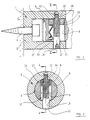
- the device shown in Figure 1 for fastening a sanitary dry fitting comprises a wall-side fastening part 1, which is cup-shaped. It rests with its bottom surface 2 on the building wall 3 and is attached to it by a central, from the inside outwardly extending screw 4 attached.
- a fitting-side fastening part 6 is inserted in the manner of a plug-coupling connection. It has a cross-sectional shape which is complementary to the cross section of the interior 5 of the wall-side fastening part 1, that is to say a circular cross section in the exemplary embodiment in FIG. 1.
- the fitting-side fastening part 6 can be in one piece with the actual sanitary dry fitting 7 (which is only partially shown in the drawing); the latter can also be releasably attached to the fitting-side fastening part in any other manner.
- the fitting-side fastening part 6 is penetrated by an opening 8 with a rectangular cross section, the boundary lines of which run perpendicular to the axis of the wall-side fastening part 1 and the fitting-side fastening part 6.
- a sliding block 9, which has an outer contour complementary to the opening 8, is slidably arranged in the opening 8.
- a threaded bolt 11 is screwed through a threaded bore 10 of the sliding block 9 and is mounted in the upper end in FIG. 1 with a pin region 12 of reduced diameter in a blind bore 13 of the wall-side fastening part 1.
- the threaded bolt 11 is supported with an annular shoulder 14 forming the transition to the pin region 12 on the wall of the interior 5 of the wall-side fastening part 1.
- the end of the threaded bolt 11 opposite the pin region 12 is passed through a through hole 15 of the wall-side fastening part 1 and is flush with its outer lateral surface.
- a screwdriver or another suitable tool with which the threaded bolt 11 rotates can be used on a slot 16 leaves.
- a leaf spring 17 is fastened to the lower end face of the sliding block 9 in FIG. 1, between the boundary surface 30 of the opening 8 of the fitting-side fastening part 6 on the left in FIG. 1 and the screw bolt 11, which in cross section has approximately the shape of a "3". If the sliding block 9 is located in the uppermost region of the opening 8, as shown in FIG. 1, the spring 17 is relaxed.
- the device for fastening a sanitary dry fitting shown in FIGS. 1 and 2 functions as follows:
- the wall-side fastening part 1 is fastened to the building wall 3 by means of the screw 4.
- the fitting-side fastening part 6, in the opening 8 of which the sliding block 9 with spring 17 is already located is inserted into the interior 5 of the wall-side fastening part 1 until the threaded bore 10 of the sliding block 9 with the blind hole 13 and the through hole 15 of the wall-side fastening part 1 flees.
- the threaded bolt 11 is inserted from below through the through hole 15 into the interior 5 of the wall-side fastening part 1 and screwed into the threaded bore 10 of the sliding block 9 until the annular shoulder 14 abuts the outer surface of the interior 5 and the pin area 12 of the threaded bolt 11 in the blind bore 13 is mounted.
- the game which can be compensated for in the device shown in Figure 1 for fastening a sanitary dry fitting between the wall-side fastening part 1 and the fitting-side fastening part 6, is determined by the dimensional change which the spring 17 has in the direction of the axis of these fastening parts 1, 6 Displacement of the sliding block 9 in the opening 8 of the fitting-side fastening part 6 experiences.
- the spring 17 can be understood as a special form of a device which converts the movement of the sliding block 9 transverse to the axis of the fastening parts 1 and 6 into a movement of the fastening part 6 on the fitting side parallel to the direction of this axis.
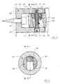
- FIGS. 3 and 4 show a further exemplary embodiment of a device for fastening a sanitary dry fitting, which is largely similar to that described above with reference to FIGS. 1 and 2. Appropriate Parts are therefore marked with the same reference number plus 100.
- a fitting-side fastening part 106 which is integral with the sanitary dry fitting 107, is in the interior 105 of the wall-side Fastening part 101 inserted in the manner of a plug.
- the fitting-side fastening part 105 has an opening which is rectangular in cross-section, the lateral boundary lines of which in the section in FIG. 3 no longer run at right angles but at an angle to the axis of the fastening parts 1 and 6.
- the sliding block 109 which is also displaceably arranged in the opening 108 in the exemplary embodiment according to FIGS. 3 and 4, has boundary surfaces in the section according to FIG. 3, which extend obliquely to the axis of the fastening parts 101 and 106.
- a threaded bolt 111 is passed through a through hole 115 and a threaded hole 110 in the sliding block 109, lies with an annular shoulder 114 against the wall of the interior 105 of the wall-side fastening part 101 and is supported with a pin region 112 in a blind hole 113 of the wall-side fastening part 101.
- a spring corresponding to the spring 17 of the exemplary embodiment according to FIG. 1 is not provided in FIG. 3.
- the device which converts the "transverse movement" of the sliding block 109 in the opening 108 into an axial movement of the fitting-side fastening part 106 is rather inclined by the extending boundary surface 130 of the opening 108 of the fitting-side fastening part 106 and the cooperating oblique surface 131 of the sliding block 109 are formed.
- no further explanation is required that a movement of the sliding block 109 caused by rotation of the threaded bolt 111 and directed downward in FIG. 3 generates a force component on the fitting-side fastening part 106, which in FIG. 3 moves it to the left, that is to say on the building wall 103 too moved.
- FIG. 3 The principle of operation of the exemplary embodiment shown in FIG. 3 thus corresponds to that of the exemplary embodiment according to FIGS. 1 and 2. Additional explanations are not required.
- a spring 118 is also shown in FIG. 3, which is fastened to the sliding block 109 and extends into a groove 119 on the boundary surface of the sliding block 109 on the right in FIG. 3. It rests under elastic tension at the same time on the right-hand boundary surface of the opening 108 in FIG. 3 in the fitting-side fastening part 106.
- This spring 118 has the task of preventing inadvertent displacement of the sliding block 109 within the opening 108 if the fitting-side fastening part 106 has not yet been inserted into the wall-side fastening part 101 and the position of the sliding block 109 has not yet been determined by the threaded bolt 111.
- the sliding block 109 is positioned in the opening 108 in the position which is shown in FIG. 3. The spring 118 then prevents the sliding block 109 from making undefined movements in the opening 108.
- FIG. 5 The exemplary embodiment which is shown in FIG. 5 largely corresponds to that of FIG. 3.
- a detailed description can therefore be given to be dispensed with;
- Corresponding parts of the exemplary embodiment according to FIG. 5 are identified by the same reference numerals as in FIG. 1, but plus 200.
- a fitting-side fastening part 206 which is integral with the dry fitting 207, is inserted into the cup-shaped fastening part 201 fastened to the building wall 203 by means of a screw 204.
- the fitting-side fastening part 206 has an opening 208, the left delimitation surface 230 in FIG. 5 of which runs obliquely to the axis of the fastening surface 201, 206 and the delimitation surface right in FIG.
- a sliding block 209 is arranged displaceably in the opening 208 and bears against the parallel limiting surface 230 of the opening 108 on the left-hand side in FIG.
- the sliding block 209 is formed with a one-piece spring extension 218, which rests under elastic deformation on the right-hand boundary surface of the opening 208 in FIG. 5. All other components correspond to those of the embodiment of Figure 3. Accordingly, the function is the same.
- the threaded hole 210 in the sliding block 209 is first brought into alignment with the through-hole 215 and the blind hole 213 in the wall-side fastening part 201.
- the threaded bolt 211 is then screwed into the threaded bore 210 of the sliding block 209 from below until the position shown in FIG. 5 is reached. A further rotation of the threaded bolt 211 leads to a downward movement of the sliding block 209 in the opening 208 in FIG. 5, the spring section 218 of the sliding block 209 also being compressed.
- the spring 118, the spring section 218 in the embodiment of FIG. 5 only prevents the slide block 209 from performing undesired movements within the opening 208 when the fitting-side fastening part 206 is removed.
- FIG. 6 The exemplary embodiment of a device for fastening a sanitary dry fitting finally shown in FIG. 6 represents a kind of "kinematic reversal" of the exemplary embodiment according to FIG. 5.
- components which correspond to those of FIG. 1 are again identified by the same reference number plus 300.
- the wall-side fastening part 301 is designed as a flange which is attached to the mounting wall 303 with a plurality of fastening screws 304.
- the wall-side fastening part 301 is equipped with a one-piece, cylindrical projection 320, through which an opening 308 extends.
- the boundary surface of the opening 308 on the left in FIG. 6 and adjacent to the building wall 203 runs perpendicular to the axis of the cylindrical projection 320, while the boundary surface 330 of the opening 308 in FIG. 6 is inclined with respect to this axis. However, the inclination runs in the opposite direction to that of FIG. 5, which is a direct consequence of the kinematic reversal of movement.
- a sliding block 309 is slidably arranged in the opening 308, the right-hand delimitation surface 331 in FIG. 6 running parallel to the delimitation surface 330 there of the opening 308 of the cylindrical projection 320 and abutting the latter.
- a spring section 318 is integrally formed on the sliding block 309, which is under elastic Deformation on the left boundary surface of the opening 309 is present.
- the fitting-side fastening part 306 is provided with a cylindrical interior 305 which is complementary to the projection 320 of the wall-side fastening part 301 and which can be pushed over the cylindrical projection 320.
- an annular flange 321 is formed on the fitting-side fastening part 306, which covers the fastening screws 304.
- a threaded bolt 311 is passed through a through hole 315 in the fitting-side fastening part 306 and screwed into a threaded hole 310 of the sliding block 309. It rests with an annular shoulder 314 on the lateral surface of the interior 305 of the fitting-side fastening part 306.
- a reduced diameter portion 312 of the threaded bolt 311 is mounted in a blind hole 313 of the fitting-side fastening part 306.
- the play, which can be compensated for by an axial movement of the fitting-side fastening part, is clearly determined by the slope of the opening, which is in the exemplary embodiment according to FIGS. 3 to 5 in the fitting-side fastening part, in the exemplary embodiment according to FIG. 6 in the wall-side fastening part.
- a spring element which prevents unintentional movement of the sliding block in the associated opening, was only shown and described in the exemplary embodiments according to FIGS. 3 to 6.
- the spring 17 has an additional section which, similar to the spring 118, extends into a groove on the boundary surface of the sliding block 9 and rests with elastic deformation on the boundary surface 30 of the opening 8 on the left in FIG.
- All of the exemplary embodiments are distinguished by the fact that the outer end face of the threaded bolt 11, 111, 211, 311 always remains in alignment with the outer end face of the fastening part on which the threaded bolt is mounted. This is important from an aesthetic point of view.
Landscapes
- Engineering & Computer Science (AREA)
- General Engineering & Computer Science (AREA)
- Mechanical Engineering (AREA)
- Health & Medical Sciences (AREA)
- Public Health (AREA)
- Dowels (AREA)
- Residential Or Office Buildings (AREA)
- Mirrors, Picture Frames, Photograph Stands, And Related Fastening Devices (AREA)
Priority Applications (1)
| Application Number | Priority Date | Filing Date | Title |
|---|---|---|---|
| AT90118801T ATE101789T1 (de) | 1989-10-04 | 1990-10-01 | Einrichtung zur befestigung einer sanitaeren trockenarmatur. |
Applications Claiming Priority (2)
| Application Number | Priority Date | Filing Date | Title |
|---|---|---|---|
| DE3933132A DE3933132C1 (enExample) | 1989-10-04 | 1989-10-04 | |
| DE3933132 | 1989-10-04 |
Publications (2)
| Publication Number | Publication Date |
|---|---|
| EP0421321A1 EP0421321A1 (de) | 1991-04-10 |
| EP0421321B1 true EP0421321B1 (de) | 1994-02-23 |
Family
ID=6390820
Family Applications (1)
| Application Number | Title | Priority Date | Filing Date |
|---|---|---|---|
| EP90118801A Expired - Lifetime EP0421321B1 (de) | 1989-10-04 | 1990-10-01 | Einrichtung zur Befestigung einer sanitären Trockenarmatur |
Country Status (4)
| Country | Link |
|---|---|
| EP (1) | EP0421321B1 (enExample) |
| AT (1) | ATE101789T1 (enExample) |
| DE (1) | DE3933132C1 (enExample) |
| ES (1) | ES2050326T3 (enExample) |
Cited By (1)
| Publication number | Priority date | Publication date | Assignee | Title |
|---|---|---|---|---|
| US20140138505A1 (en) * | 2011-07-07 | 2014-05-22 | Andrew Keith Maclaren-Taylor | Mounting system |
Families Citing this family (3)
| Publication number | Priority date | Publication date | Assignee | Title |
|---|---|---|---|---|
| DE19900612C2 (de) * | 1999-01-11 | 2003-02-27 | Heinrich Plewnia | Vorrichtung zum Aufhängen von Gegenständen an Deckenverkleidungen |
| DE19912336B4 (de) * | 1999-03-19 | 2005-08-18 | Hansa Metallwerke Ag | System zur lösbaren Befestigung eines Teiles, insbesondere einer sanitären Trockenarmatur, an einer Wand |
| DE202014102388U1 (de) * | 2014-05-21 | 2015-08-28 | Nie Wieder Bohren Ag | Montagesystem |
Citations (1)
| Publication number | Priority date | Publication date | Assignee | Title |
|---|---|---|---|---|
| DE1110388B (de) * | 1934-10-17 | 1961-07-06 | Gartner & Co J | Spannelement fuer Metallhohlpfosten, insbesondere von versetzbaren Zwischen-waenden |
Family Cites Families (6)
| Publication number | Priority date | Publication date | Assignee | Title |
|---|---|---|---|---|
| BE767043A (fr) * | 1971-05-12 | 1971-10-01 | Janssen Leopold M L | Cloison double paroi et elements de cloison. |
| DE3105216A1 (de) * | 1981-02-13 | 1982-09-09 | HEWI Heinrich Wilke GmbH, 3548 Arolsen | Handtuchhalter mit zwei uebereinander angeordneten haltearmen |
| ATE26388T1 (de) * | 1983-06-30 | 1987-04-15 | Keune & Co Kg P | Wandhalter fuer eine armatur. |
| DE8320860U1 (de) * | 1983-07-20 | 1983-12-01 | Schulte & Co, 5750 Menden | Vorrichtung zur befestigung von sanitaeren ausstattungsarmaturen an einer wand |
| GB2215425B (en) * | 1988-02-05 | 1992-09-02 | Kaye Aluminium Ltd | Improved construction element |
| DE8802016U1 (de) * | 1988-02-17 | 1988-04-07 | Keuco GmbH & Co KG, 5870 Hemer | Wandhalter für eine Armatur |
-
1989
- 1989-10-04 DE DE3933132A patent/DE3933132C1/de not_active Expired - Fee Related
-
1990
- 1990-10-01 AT AT90118801T patent/ATE101789T1/de active
- 1990-10-01 ES ES90118801T patent/ES2050326T3/es not_active Expired - Lifetime
- 1990-10-01 EP EP90118801A patent/EP0421321B1/de not_active Expired - Lifetime
Patent Citations (1)
| Publication number | Priority date | Publication date | Assignee | Title |
|---|---|---|---|---|
| DE1110388B (de) * | 1934-10-17 | 1961-07-06 | Gartner & Co J | Spannelement fuer Metallhohlpfosten, insbesondere von versetzbaren Zwischen-waenden |
Cited By (2)
| Publication number | Priority date | Publication date | Assignee | Title |
|---|---|---|---|---|
| US20140138505A1 (en) * | 2011-07-07 | 2014-05-22 | Andrew Keith Maclaren-Taylor | Mounting system |
| US9526381B2 (en) * | 2011-07-07 | 2016-12-27 | Andrew Keith Maclaren Taylor | Mounting system |
Also Published As
| Publication number | Publication date |
|---|---|
| ATE101789T1 (de) | 1994-03-15 |
| DE3933132C1 (enExample) | 1991-05-29 |
| ES2050326T3 (es) | 1994-05-16 |
| EP0421321A1 (de) | 1991-04-10 |
Similar Documents
| Publication | Publication Date | Title |
|---|---|---|
| WO1994007040A1 (de) | Vorrichtung zum verbinden von wenigstens zwei elementen | |
| EP0761130A2 (de) | Halterungs-Beschlag für Frontblenden von Schubladen | |
| WO2018204956A1 (de) | Möbelantrieb | |
| EP1109983A1 (de) | Anschraubscharnier mit raststellung | |
| AT517612B1 (de) | Möbelbeschlag | |
| DE102004001788A1 (de) | Anordnung zur axial verstellbaren Halterung eines berührungslos arbeitenden Sensors | |
| EP0421321B1 (de) | Einrichtung zur Befestigung einer sanitären Trockenarmatur | |
| DE29511547U1 (de) | Vorrichtung zur axial unverschieblichen, lösbaren Befestigung einer Handhabe an einem Lagerteil, insbesondere für Türdrücker, Fenstergriffe o.dgl. | |
| EP1781882A1 (de) | Verstelleinrichtung für möbelteile | |
| DE2237799C3 (de) | Schnäpperscharnier für Möbeltüren o.dgl | |
| EP3173556B1 (de) | Montageelement zur befestigung von türbändern | |
| DE29505752U1 (de) | Vorrichtung zum Verbinden von Platten mittels Verschraubung | |
| EP1820927B1 (de) | Buchsenmodul | |
| AT396005B (de) | Befestigungselement mit einer duebelartigen buchse | |
| EP1335138B1 (de) | Profilstabverbinder | |
| EP1457137A1 (de) | Kupplung für ausziehbare Schubladen von Möbelstücken | |
| DE2343933A1 (de) | Distanzhalter zwischen dem getriebegehaeuse eines einsteck-kantengetriebes und einer damit ueber ankerschrauben verbindbaren lagerrosette eines bedienungshebels | |
| EP1563152A1 (de) | Gelenkband | |
| DE19717116B4 (de) | Drehlager | |
| EP2446776A1 (de) | Verbindungsvorrichtung zum Verbinden eines ersten und eines zweiten Möbelbauteils mit einem dritten Möbelbauteil, Teilesatz sowie Tisch | |
| EP0733746A2 (de) | Halter | |
| DE3512425A1 (de) | Hohlwanddose fuer elektrische installationseinrichtungen, insbesondere schalter, steckdosen od.dgl. | |
| DE8333532U1 (de) | Tisch | |
| AT403637B (de) | Elektrisches installationsgerät | |
| DE4425035A1 (de) | Kopplungsvorrichtung |
Legal Events
| Date | Code | Title | Description |
|---|---|---|---|
| PUAI | Public reference made under article 153(3) epc to a published international application that has entered the european phase |
Free format text: ORIGINAL CODE: 0009012 |
|
| AK | Designated contracting states |
Kind code of ref document: A1 Designated state(s): AT BE CH ES FR GB IT LI NL |
|
| 17P | Request for examination filed |
Effective date: 19910829 |
|
| 17Q | First examination report despatched |
Effective date: 19911016 |
|
| GRAA | (expected) grant |
Free format text: ORIGINAL CODE: 0009210 |
|
| AK | Designated contracting states |
Kind code of ref document: B1 Designated state(s): AT BE CH ES FR GB IT LI NL |
|
| REF | Corresponds to: |
Ref document number: 101789 Country of ref document: AT Date of ref document: 19940315 Kind code of ref document: T |
|
| ET | Fr: translation filed | ||
| GBT | Gb: translation of ep patent filed (gb section 77(6)(a)/1977) |
Effective date: 19940302 |
|
| REG | Reference to a national code |
Ref country code: ES Ref legal event code: FG2A Ref document number: 2050326 Country of ref document: ES Kind code of ref document: T3 |
|
| ITF | It: translation for a ep patent filed | ||
| PLBE | No opposition filed within time limit |
Free format text: ORIGINAL CODE: 0009261 |
|
| STAA | Information on the status of an ep patent application or granted ep patent |
Free format text: STATUS: NO OPPOSITION FILED WITHIN TIME LIMIT |
|
| 26N | No opposition filed | ||
| PGFP | Annual fee paid to national office [announced via postgrant information from national office to epo] |
Ref country code: GB Payment date: 19990929 Year of fee payment: 10 |
|
| PGFP | Annual fee paid to national office [announced via postgrant information from national office to epo] |
Ref country code: FR Payment date: 19991008 Year of fee payment: 10 |
|
| PGFP | Annual fee paid to national office [announced via postgrant information from national office to epo] |
Ref country code: AT Payment date: 19991012 Year of fee payment: 10 |
|
| PGFP | Annual fee paid to national office [announced via postgrant information from national office to epo] |
Ref country code: BE Payment date: 19991015 Year of fee payment: 10 |
|
| PGFP | Annual fee paid to national office [announced via postgrant information from national office to epo] |
Ref country code: CH Payment date: 19991021 Year of fee payment: 10 |
|
| PGFP | Annual fee paid to national office [announced via postgrant information from national office to epo] |
Ref country code: ES Payment date: 19991026 Year of fee payment: 10 |
|
| PGFP | Annual fee paid to national office [announced via postgrant information from national office to epo] |
Ref country code: NL Payment date: 19991029 Year of fee payment: 10 |
|
| PG25 | Lapsed in a contracting state [announced via postgrant information from national office to epo] |
Ref country code: GB Free format text: LAPSE BECAUSE OF NON-PAYMENT OF DUE FEES Effective date: 20001001 Ref country code: AT Free format text: LAPSE BECAUSE OF NON-PAYMENT OF DUE FEES Effective date: 20001001 |
|
| PG25 | Lapsed in a contracting state [announced via postgrant information from national office to epo] |
Ref country code: ES Free format text: LAPSE BECAUSE OF NON-PAYMENT OF DUE FEES Effective date: 20001002 |
|
| PG25 | Lapsed in a contracting state [announced via postgrant information from national office to epo] |
Ref country code: LI Free format text: LAPSE BECAUSE OF NON-PAYMENT OF DUE FEES Effective date: 20001031 Ref country code: CH Free format text: LAPSE BECAUSE OF NON-PAYMENT OF DUE FEES Effective date: 20001031 Ref country code: BE Free format text: LAPSE BECAUSE OF NON-PAYMENT OF DUE FEES Effective date: 20001031 |
|
| BERE | Be: lapsed |
Owner name: HANSA METALLWERKE A.G. Effective date: 20001031 |
|
| PG25 | Lapsed in a contracting state [announced via postgrant information from national office to epo] |
Ref country code: NL Free format text: LAPSE BECAUSE OF NON-PAYMENT OF DUE FEES Effective date: 20010501 |
|
| GBPC | Gb: european patent ceased through non-payment of renewal fee |
Effective date: 20001001 |
|
| REG | Reference to a national code |
Ref country code: CH Ref legal event code: PL |
|
| PG25 | Lapsed in a contracting state [announced via postgrant information from national office to epo] |
Ref country code: FR Free format text: LAPSE BECAUSE OF NON-PAYMENT OF DUE FEES Effective date: 20010629 |
|
| NLV4 | Nl: lapsed or anulled due to non-payment of the annual fee |
Effective date: 20010501 |
|
| REG | Reference to a national code |
Ref country code: FR Ref legal event code: ST |
|
| REG | Reference to a national code |
Ref country code: ES Ref legal event code: FD2A Effective date: 20011113 |
|
| PG25 | Lapsed in a contracting state [announced via postgrant information from national office to epo] |
Ref country code: IT Free format text: LAPSE BECAUSE OF NON-PAYMENT OF DUE FEES;WARNING: LAPSES OF ITALIAN PATENTS WITH EFFECTIVE DATE BEFORE 2007 MAY HAVE OCCURRED AT ANY TIME BEFORE 2007. THE CORRECT EFFECTIVE DATE MAY BE DIFFERENT FROM THE ONE RECORDED. Effective date: 20051001 |