EP0421091A1 - Überlapp- oder Steg-Schweissnaht für verzinkte Bleche - Google Patents
Überlapp- oder Steg-Schweissnaht für verzinkte Bleche Download PDFInfo
- Publication number
- EP0421091A1 EP0421091A1 EP90115438A EP90115438A EP0421091A1 EP 0421091 A1 EP0421091 A1 EP 0421091A1 EP 90115438 A EP90115438 A EP 90115438A EP 90115438 A EP90115438 A EP 90115438A EP 0421091 A1 EP0421091 A1 EP 0421091A1
- Authority
- EP
- European Patent Office
- Prior art keywords
- weld seam
- knobs
- weld
- laser weld
- overlap
- Prior art date
- Legal status (The legal status is an assumption and is not a legal conclusion. Google has not performed a legal analysis and makes no representation as to the accuracy of the status listed.)
- Granted
Links
Images
Classifications
-
- B—PERFORMING OPERATIONS; TRANSPORTING
- B23—MACHINE TOOLS; METAL-WORKING NOT OTHERWISE PROVIDED FOR
- B23K—SOLDERING OR UNSOLDERING; WELDING; CLADDING OR PLATING BY SOLDERING OR WELDING; CUTTING BY APPLYING HEAT LOCALLY, e.g. FLAME CUTTING; WORKING BY LASER BEAM
- B23K33/00—Specially-profiled edge portions of workpieces for making soldering or welding connections; Filling the seams formed thereby
- B23K33/004—Filling of continuous seams
- B23K33/008—Filling of continuous seams for automotive applications
-
- B—PERFORMING OPERATIONS; TRANSPORTING
- B23—MACHINE TOOLS; METAL-WORKING NOT OTHERWISE PROVIDED FOR
- B23K—SOLDERING OR UNSOLDERING; WELDING; CLADDING OR PLATING BY SOLDERING OR WELDING; CUTTING BY APPLYING HEAT LOCALLY, e.g. FLAME CUTTING; WORKING BY LASER BEAM
- B23K26/00—Working by laser beam, e.g. welding, cutting or boring
- B23K26/20—Bonding
- B23K26/21—Bonding by welding
- B23K26/24—Seam welding
- B23K26/244—Overlap seam welding
-
- B—PERFORMING OPERATIONS; TRANSPORTING
- B23—MACHINE TOOLS; METAL-WORKING NOT OTHERWISE PROVIDED FOR
- B23K—SOLDERING OR UNSOLDERING; WELDING; CLADDING OR PLATING BY SOLDERING OR WELDING; CUTTING BY APPLYING HEAT LOCALLY, e.g. FLAME CUTTING; WORKING BY LASER BEAM
- B23K2101/00—Articles made by soldering, welding or cutting
- B23K2101/34—Coated articles ; Surface treated articles
-
- B—PERFORMING OPERATIONS; TRANSPORTING
- B23—MACHINE TOOLS; METAL-WORKING NOT OTHERWISE PROVIDED FOR
- B23K—SOLDERING OR UNSOLDERING; WELDING; CLADDING OR PLATING BY SOLDERING OR WELDING; CUTTING BY APPLYING HEAT LOCALLY, e.g. FLAME CUTTING; WORKING BY LASER BEAM
- B23K2103/00—Materials to be soldered, welded or cut
- B23K2103/08—Non-ferrous metals or alloys
Definitions
- the invention relates to an overlap or web weld seam for galvanized sheets according to the preamble of claim 1, as is known for example from JP-56-62 688 (A).
- JP-56-62 688 (A) presents a laser weld for galvanized sheets.
- spacer inserts are glued between the sheets in the overlap area on both sides of the laser weld seam.
- These nub-like inserts run parallel to the longitudinal direction of the laser weld seam and have a mutual transverse distance that is larger than the width of the weld seam.
- there are two large escape channels for the evaporating zinc which are oriented transversely to the longitudinal direction of the laser weld seam. This method proves to be reliable in terms of its function, but it is too time and cost intensive for production, since an additional material has to be arranged between the sheets.
- the object of the invention is to further develop the generic overlap or web weld seam in such a way that galvanized sheets can be welded more cheaply.
- the object is achieved with the characterizing features of claim 1.
- the knobs or beads pressed into the sheet secure the spacing of the sheet layers when the sheets are tensioned against each other in the overlap area and thus the short escape channels running in two directions transverse to the laser weld seam. Further advantageous embodiments of the invention can be found in the subclaims.
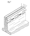
- FIG 1 two galvanized sheets 1, 1 'are shown, which are bent at a right angle at one of their edges and to this area, which forms the overlapped area 5, approximated and then welded together.
- One sheet 1 has arranged along a line of alignment squat 4, which are pressed out of a sheet 1 defined in the direction of the other sheet 1 '. In this way, they are arranged between the sheets 1, 1 'in the overlap area 5 to secure the distance.
- laser welding seams 3 are provided, which likewise extend along this line of alignment.
- the laser welds 3 are at a distance from the squats 4, which means that short air ducts which always run in two spatial directions are available for the zinc of the coating 2 of the sheets 1, 1 'which evaporates during welding.
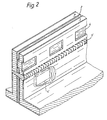
- FIG. 1 Another embodiment is shown in FIG.
- the hops 4, 4 ' are arranged on both sides of a between the two lines of alignment of the knobs 4, 4', continuous laser weld 3 'at a distance from this.
- the first knobs 4 of a sheet 1 are all on one side of the weld 3 'and the other knobs 4' of the other sheet 1 ⁇ attached on the other side.
- the first knobs 4 are arranged in the area of the gaps of the second knobs 4 'arranged along the second alignment line, which runs on the other longitudinal side of the laser weld 3'.
Landscapes
- Engineering & Computer Science (AREA)
- Mechanical Engineering (AREA)
- Physics & Mathematics (AREA)
- Optics & Photonics (AREA)
- Plasma & Fusion (AREA)
- Laser Beam Processing (AREA)
Abstract
Description
- Die Erfindung betrifft eine Überlapp- oder Steg-Schweißnaht für verzinkte Bleche nach dem Oberbegriff des Anspruchs 1, wie sie beispielsweise aus der JP-56-62 688 (A) als bekannt hervorgeht.
- In der JP-56-62 688 (A) ist eine Laser-Schweißnaht für verzinkte Bleche vorgestellt. Um Gaseinschlüsse der beim Schweißen verdampfenden Zinkschicht in die Schweißschmelze zu vermeiden, sind im Überlappungsbereich beidseitig zur Laser-Schweißnaht zwischen den Blechen distanzsichernde Einlagen angeklebt. Diese noppenartigen Einlagen verlaufen parallel zur Längsrichtung der Laser-Schweißnaht und weisen einen gegenseitigen Querabstand auf, der größer als die Schweißnahtbreite ist. Dadurch sind beim Verschweißen zwei großflächige, quer zur Längsrichtung der Laser-Schweißnaht gerichtete Fluchtkanäle für das verdampfende Zink vorhanden. Diese Methode erweist sich von ihrer Funktion zwar als zuverlässig, für die Produktion ist sie jedoch, da ein zusätzliches Material zwischen den Blechen angeordnet werden muß, zu zeit- und kostenintensiv.
- In der gattungsbildenden Schrift ist ferner ein weiteres Beispiel aufgeführt, bei dem im Überlappungsbereich in eines der Bleche eine dem Verlauf der Schweißnaht folgende Längssicke von trapezförmigem Querschnitt eingedrückt ist, die mit dem Gegenblech einen dem Schweißnahtverlauf folgenden Längskanal für den Zinkdampf bildet. Bei einer solchen Anordnung ergeben sich allerdings u. U. erhebliche Strömungswiderstände, die die Drainagewirkung beeinträchtigen.
- Die Aufgabe der Erfindung ist es, die gattungsgemäß zugrundegelegte Überlapp- oder Steg-Schweißnaht dahingehend weiterzuentwickeln, daß verzinkte Bleche kostengünstiger verschweißt werden können.
- Die Aufgabe wird erfindungsgemäß mit den kennzeichnenden Merkmalen des Anspruchs 1 gelöst. Die in das Blech eingedrückten Noppen bzw. Sicken sichern bei einem Spannen der Bleche gegeneinander im Überlappungsbereich den Abstand der Blechlagen und somit die in zwei Richtungen quer zur Laser-Schweißnaht verlaufenden kurzen Fluchtkanäle. Weitere vorteilhafte Ausgestaltungen der Erfindung sind den Unteransprüchen entnehmbar.
- Zwei Ausführungsbeispiele sind in den Zeichnungen dargestellt und werden im folgenden erläutert. Dabei zeigt:
- Figur 1 eine Laser-Schweißnaht zwischen den Noppen entlang der gleichen Fluchtlinie und
- Figur 2 die Laser-Schweißnaht zwischen zwei Noppenreihen.
- In Figur 1 sind zwei verzinkte Bleche 1, 1′ dargestellt, die an einem ihrer Ränder rechtwinklig gebogen und an diesen Bereich, der den überlappten Bereich 5 bildet, einander angenähert und anschließend miteinander verschweißt werden. Das eine Blech 1 weist entlang einer Fluchtlinie angeordnete Hocken 4 auf, die aus dem einen Blech 1 definiert in Richtung des anderen Bleches 1′ eingedrückt sind. Auf diese Art sind sie zwischen den Blechen 1, 1′ im Überlappungsbereich 5 distanzsichernd angeordnet. In den Bereichen zwischen den Noppen 4 entlang der Fluchtlinie sind Laser-Schweißnähte 3 angebracht, die sich gleichfalls entlang dieser Fluchtlinie erstrecken. Die Laser-Schweißnähte 3 weisen von den Hocken 4 einen Abstand auf, womit immer in zwei Raumrichtungen verlaufende kurze Luftkanäle für das beim Verschweißen verdampfende Zink der Beschichtung 2 der Bleche 1, 1′ zur Verfügung steht.
- In Figur 2 ist ein weiteres Ausführungsbeispiel abgebildet. In diesem Fall weist jedes der beiden Bleche 1, 1˝ entlang einer jeweils einem Blech zugeordneten Fluchtlinie angeordnete Noppen 4, 4′ auf. Die Hoppen 4, 4′ sind beidseitig einer zwischen den beiden Fluchtlinien der Noppen 4, 4′ angebrachten, durchgehenden Laser-Schweißnaht 3′ mit Abstand zu dieser angeordnet. Die ersten Noppen 4 des einen Bleches 1 sind hierbei alle auf einer Seite der Schweißnaht 3′ und die anderen Noppen 4′ des anderen Bleches 1˝ auf der anderen Seite angebracht. Ferner sind die ersten Noppen 4 im Bereich der Lücken der entlang der zweiten Fluchtlinie, die auf der anderen Längsseite der Laserschweißnaht 3′ verläuft, angeordneten zweiten Noppen 4′ angebracht. Damit wird das Spannen der beiden Bleche 1, 1˝ aneinander erleichtert, da die Bleche 1, 1˝ im überlappten Bereich 5 nicht gegeneinander verkippen können. Um denselben Effekt zu erreichen ist es natürlich auch möglich, die Noppen sowohl auf Lücken als auch beidseitig der Laserschweißnaht in einem einzigen Blech anzuordnen.
Claims (4)
dadurch gekennzeichnet,
daß die Noppen (4, 4′) bzw. Sicken in wenigstens eines der Bleche (1, 1′, 1˝) integriert und in es eingedrückt sind.
dadurch gekennzeichnet,
daß die Noppen (4, 4′) bzw. Sicken beidseitig der Laser-Schweißnaht (3, 3′) angeordnet sind.
dadurch gekennzeichnet,
daß die Noppen (4, 4′) bzw. Sicken auf der einen Längsseite der Laserschweißnaht (3, 3′) gegenüberliegend den Lücken zwischen zwei benachbarten Noppen (4, 4′) der anderen Längsseite angeordnet sind.
dadurch gekennzeichnet,
daß die in der gleichen Fluchtlinie wie die Noppen (4) verlaufende Laser-Schweißnaht (3) unterbrochen und nur im Bereich zwischen den Hoppen (4) verläuft.
Applications Claiming Priority (2)
| Application Number | Priority Date | Filing Date | Title |
|---|---|---|---|
| DE3933408A DE3933408A1 (de) | 1989-10-06 | 1989-10-06 | Ueberlapp- oder steg-schweissnaht fuer verzinkte bleche |
| DE3933408 | 1989-10-06 |
Publications (2)
| Publication Number | Publication Date |
|---|---|
| EP0421091A1 true EP0421091A1 (de) | 1991-04-10 |
| EP0421091B1 EP0421091B1 (de) | 1993-11-10 |
Family
ID=6390964
Family Applications (1)
| Application Number | Title | Priority Date | Filing Date |
|---|---|---|---|
| EP90115438A Expired - Lifetime EP0421091B1 (de) | 1989-10-06 | 1990-08-11 | Überlapp- oder Steg-Schweissnaht für verzinkte Bleche |
Country Status (5)
| Country | Link |
|---|---|
| US (1) | US5104032A (de) |
| EP (1) | EP0421091B1 (de) |
| JP (1) | JP2571976B2 (de) |
| DE (1) | DE3933408A1 (de) |
| ES (1) | ES2048374T3 (de) |
Cited By (4)
| Publication number | Priority date | Publication date | Assignee | Title |
|---|---|---|---|---|
| EP0511746A3 (en) * | 1991-04-30 | 1993-01-20 | Toyo Seikan Kaisha Limited | Method of making articles by laser beam welding |
| US5454480A (en) * | 1993-10-21 | 1995-10-03 | Morris Holmes & Co. | Flangeless fuel tank |
| FR2731373A1 (fr) * | 1995-03-09 | 1996-09-13 | Peugeot | Procede de soudage de toles par un faisceau laser et assemblage de toles soudees obtenu par ce procede |
| EP1985402A3 (de) * | 2000-03-30 | 2008-11-05 | Fuji Jukogyo Kabushiki Kaisha | Laserschweissverfahren zum Zusammenschweissen von überlappten Stahlblechen |
Families Citing this family (35)
| Publication number | Priority date | Publication date | Assignee | Title |
|---|---|---|---|---|
| EP0628375B1 (de) * | 1993-05-21 | 2002-03-20 | Toyota Jidosha Kabushiki Kaisha | Laserschweissverfahren |
| US5389761A (en) * | 1993-09-17 | 1995-02-14 | General Motors Corporation | Method and apparatus for cleaning metal pieces prior to resistive seam welding or laser lap seam welding |
| US5656184A (en) * | 1995-03-27 | 1997-08-12 | General Electric Company | Method of laser welding open receptacles |
| DE19616062A1 (de) * | 1996-04-23 | 1997-05-07 | Krupp Ag Hoesch Krupp | Verfahren zum Herstellen lasergeschweißter Doppelplatinen |
| CA2209804A1 (en) * | 1997-08-15 | 1999-02-15 | Hongping Gu | Method of laser beam welding of zinc-coated steel sheet |
| US6639176B1 (en) * | 1998-11-13 | 2003-10-28 | Elpatronic Ag | Method and device for producing welded blanks |
| JP3614062B2 (ja) * | 1999-12-07 | 2005-01-26 | トヨタ自動車株式会社 | 重ねレーザ溶接方法 |
| US6460007B1 (en) | 2000-03-20 | 2002-10-01 | Daimlerchrysler Corporation | Method and apparatus for determination of resistance spot welded flange width |
| DE10042538A1 (de) * | 2000-08-30 | 2002-03-14 | Volkswagen Ag | Verfahren zum Laserschweißen mit definierter Spaltweite |
| DE10053789B4 (de) * | 2000-10-30 | 2009-11-26 | Volkswagen Ag | Laserschweißverfahren |
| AU2002253572A1 (en) * | 2001-04-27 | 2002-11-11 | Honda Giken Kogyo Kabushiki Kaisha | Method and appratus for laser beam welding of overlapping sheets |
| DE10158388C1 (de) * | 2001-11-28 | 2003-04-10 | Thyssenkrupp Drauz Ingenieurbe | Verfahren zum Abführen des gasförmigen Beschichtungswerkstoffes von Blechen |
| CN100337781C (zh) | 2002-06-27 | 2007-09-19 | 住友金属工业株式会社 | 用于焊接的物料以及焊接物件 |
| DE10235856A1 (de) * | 2002-08-05 | 2004-02-26 | Abb Research Ltd. | Verfahren und Vorrichtung zum Verbinden von Bauteilen |
| DE10235857A1 (de) * | 2002-08-05 | 2004-02-26 | Abb Research Ltd. | Verfahren und Vorrichtung zum Verbinden von Bauteilen |
| DE10262053A1 (de) * | 2002-09-05 | 2004-08-12 | Daimlerchrysler Ag | Verfahren zur Laserbearbeitung beschichteter Bleche |
| DE10248402B3 (de) * | 2002-10-17 | 2004-06-09 | Audi Ag | Vorrichtung zum Schweißen von Blechverbindungen mittels eines Laserstrahls |
| DE10261655B4 (de) * | 2002-12-27 | 2011-08-11 | Volkswagen AG, 38440 | Anordnung von beschichteten Blechen zum Fügen mittels einer Laserschweißnaht |
| DE10331745B4 (de) * | 2003-07-11 | 2012-06-28 | Volkswagen Ag | Laserschweißverbindung und Verfahren zur Herstellung einer Laserschweißverbindung |
| US20060231534A1 (en) * | 2003-08-12 | 2006-10-19 | Hill John E | Method of laser welding coated members |
| DE10346264A1 (de) * | 2003-10-06 | 2005-04-28 | Daimler Chrysler Ag | Verfahren zum Verbinden zweier Werkstücke durch Schmelzschweißen |
| DE102004013374A1 (de) * | 2004-03-17 | 2005-10-06 | Volkswagen Ag | Spannvorrichtung zum Strahlschweißen von beschichteten Blechen |
| DE102004025935B4 (de) * | 2004-05-27 | 2009-03-19 | Daimler Ag | Verfahren zur Prüfung des Abstandes beschichteter Bleche für deren Schweissbearbeitung |
| JP2006095602A (ja) * | 2004-09-27 | 2006-04-13 | Dana Corp | 亜鉛めっき鋼部品の溶接方法 |
| FR2884448B1 (fr) * | 2005-04-18 | 2009-02-06 | Renault Sas | Procede d'assemblage par soudage laser par transparence de toles recouvertes d'une couche de proctection |
| DE102005040200A1 (de) | 2005-08-25 | 2007-03-01 | Volkswagen Ag | Abstandspulver für Laserschweißen |
| DE102007028137A1 (de) | 2007-06-19 | 2008-12-24 | Volkswagen Ag | Strahlschweißverfahren |
| JP5633687B2 (ja) | 2010-10-25 | 2014-12-03 | スズキ株式会社 | 亜鉛めっき鋼板製部品のレーザ重ね溶接方法 |
| JP5630699B2 (ja) | 2010-10-25 | 2014-11-26 | スズキ株式会社 | 亜鉛めっき鋼板製部品のレーザ重ね溶接方法 |
| KR101272050B1 (ko) * | 2011-11-11 | 2013-06-07 | 주식회사 성우하이텍 | 레이저 용접방법 |
| FR2983753B1 (fr) * | 2011-12-12 | 2013-12-27 | Peugeot Citroen Automobiles Sa | Procede de soudage de toles au laser avec jeu de degazage. |
| SG10201802529UA (en) | 2013-09-24 | 2018-04-27 | United Technologies Corp | Welded assemblies and methods of making welded assemblies |
| US11427144B2 (en) | 2018-11-27 | 2022-08-30 | Shape Corp. | Galvanized multi-tubular beam and method of continuously forming the same |
| US11285523B2 (en) * | 2019-06-27 | 2022-03-29 | Fca Us Llc | Metal forming method including post-forming stretching to control springback |
| CN110576261B (zh) * | 2019-08-21 | 2021-06-25 | 中车青岛四方机车车辆股份有限公司 | 激光叠焊装置及其焊接方法 |
Family Cites Families (9)
| Publication number | Priority date | Publication date | Assignee | Title |
|---|---|---|---|---|
| US3969604A (en) * | 1973-10-04 | 1976-07-13 | Ford Motor Company | Method of welding galvanized steel |
| JPS5662688A (en) * | 1979-10-24 | 1981-05-28 | Toshiba Corp | Laser welding method |
| JPS60210386A (ja) * | 1984-04-02 | 1985-10-22 | Mitsubishi Electric Corp | レ−ザ溶接方法及び装置 |
| JPS60255294A (ja) * | 1984-05-31 | 1985-12-16 | Kubota Ltd | レ−ザ溶接方法 |
| IT1182277B (it) * | 1984-09-20 | 1987-10-05 | Prima Progetti Spa | Metodo per la saldatura laser di lamiere metalliche protette con materiali a bassa temperatura di vaporizzazione |
| JPS61135495A (ja) * | 1984-12-04 | 1986-06-23 | Mitsubishi Electric Corp | レ−ザ−溶接方法 |
| FR2600923A1 (fr) * | 1986-07-02 | 1988-01-08 | Steelweld France | Procede de soudage en recouvrement d'aciers revetus au moyen d'un faisceau d'energie |
| DE3820848A1 (de) * | 1987-09-23 | 1989-04-13 | Fraunhofer Ges Forschung | Verfahren und vorrichtung zum fuegen von werkstuecken mittels laserstrahlung |
| DE3812448C1 (de) * | 1988-04-14 | 1989-06-15 | Bayerische Motoren Werke Ag, 8000 Muenchen, De |
-
1989
- 1989-10-06 DE DE3933408A patent/DE3933408A1/de active Granted
-
1990
- 1990-08-11 ES ES90115438T patent/ES2048374T3/es not_active Expired - Lifetime
- 1990-08-11 EP EP90115438A patent/EP0421091B1/de not_active Expired - Lifetime
- 1990-09-25 JP JP2252091A patent/JP2571976B2/ja not_active Expired - Lifetime
- 1990-10-02 US US07/591,947 patent/US5104032A/en not_active Expired - Lifetime
Non-Patent Citations (2)
| Title |
|---|
| PATENT ABSTRACTS OF JAPAN vol. 5, no. 123 (M-082) 08 August 1981, & JP-A-56 062688 (TOSHIBA CORP.) 28 Mai 1981, * |
| PATENT ABSTRACTS OF JAPAN vol. 8, no. 262 (M-341) 30 November 1984, & JP-A-59 133985 (TOSHIBA KK) 01 August 1984, * |
Cited By (4)
| Publication number | Priority date | Publication date | Assignee | Title |
|---|---|---|---|---|
| EP0511746A3 (en) * | 1991-04-30 | 1993-01-20 | Toyo Seikan Kaisha Limited | Method of making articles by laser beam welding |
| US5454480A (en) * | 1993-10-21 | 1995-10-03 | Morris Holmes & Co. | Flangeless fuel tank |
| FR2731373A1 (fr) * | 1995-03-09 | 1996-09-13 | Peugeot | Procede de soudage de toles par un faisceau laser et assemblage de toles soudees obtenu par ce procede |
| EP1985402A3 (de) * | 2000-03-30 | 2008-11-05 | Fuji Jukogyo Kabushiki Kaisha | Laserschweissverfahren zum Zusammenschweissen von überlappten Stahlblechen |
Also Published As
| Publication number | Publication date |
|---|---|
| ES2048374T3 (es) | 1994-03-16 |
| US5104032A (en) | 1992-04-14 |
| DE3933408A1 (de) | 1990-08-30 |
| DE3933408C2 (de) | 1991-01-24 |
| JP2571976B2 (ja) | 1997-01-16 |
| JPH03193285A (ja) | 1991-08-23 |
| EP0421091B1 (de) | 1993-11-10 |
Similar Documents
| Publication | Publication Date | Title |
|---|---|---|
| EP0421091B1 (de) | Überlapp- oder Steg-Schweissnaht für verzinkte Bleche | |
| DE69310143T2 (de) | Wärmetauscher mit geschweissten platten | |
| DE69409647T2 (de) | Plattenwärmetauscher | |
| EP0043531B1 (de) | Elektrisches Heizelement | |
| CH639186A5 (de) | Traegerplatte zum fuehren der heizungsrohre einer fussboden- oder wandheizung. | |
| EP0811818A1 (de) | Rostplatte sowie Verfahren zur Herstellung einer Rostplatte | |
| DE3107634C2 (de) | Inline-Strahlsystem einer Farbbildröhre | |
| EP0049323A1 (de) | Bodenbelag für Fahrbahnen | |
| DE4331079A1 (de) | Panzerung, insbesondere für Fahrzeuge | |
| AT408374B (de) | Plattenförmiges strangpressprofil | |
| DE19605341B4 (de) | Verfahren zum Schweißen zweier zu verbindender verzinkter Bleche | |
| EP0095744A1 (de) | Belüftungseinsatz für geschirmte Kabinen und Raumabschirmungen | |
| CH664788A5 (de) | Vorrichtung zum verbinden von zwei aneinanderstossenden daemmplatten. | |
| EP0167993B1 (de) | Aus Platten aufgebauter Wärmetauscher | |
| DE3931909C2 (de) | ||
| DE2712702C2 (de) | Vorrichtung zur Festlegung von Einbauplatten in Berieselungseinbauten von Wärmetauschern | |
| DE2950751A1 (de) | Winkeltraeger in geschweisster kastenbauweise | |
| DE10261655A1 (de) | Laserverschweißnaht für beschichtete Bleche, insbesondere verzinkte Bleche | |
| DE3606676A1 (de) | Schweissfuge fuer eine t-verbindung | |
| DE29613310U1 (de) | Bitumenbahn | |
| EP0050709A1 (de) | Siebplatte | |
| DE19851808A1 (de) | Bitumenschweißbahn | |
| DE3619181C2 (de) | ||
| DE4111606C1 (en) | Fluid flow distribution with flow obstacles - which deflect as diffusion two part-flows orthogonally to total flow direction | |
| EP0950640B1 (de) | Füllmaterial für Tropfkörper und Verfahren zum Herstellen desselben |
Legal Events
| Date | Code | Title | Description |
|---|---|---|---|
| PUAI | Public reference made under article 153(3) epc to a published international application that has entered the european phase |
Free format text: ORIGINAL CODE: 0009012 |
|
| 17P | Request for examination filed |
Effective date: 19910206 |
|
| AK | Designated contracting states |
Kind code of ref document: A1 Designated state(s): ES FR GB IT SE |
|
| 17Q | First examination report despatched |
Effective date: 19920512 |
|
| ITF | It: translation for a ep patent filed | ||
| GRAA | (expected) grant |
Free format text: ORIGINAL CODE: 0009210 |
|
| AK | Designated contracting states |
Kind code of ref document: B1 Designated state(s): ES FR GB IT SE |
|
| GBT | Gb: translation of ep patent filed (gb section 77(6)(a)/1977) |
Effective date: 19931208 |
|
| ET | Fr: translation filed | ||
| REG | Reference to a national code |
Ref country code: ES Ref legal event code: FG2A Ref document number: 2048374 Country of ref document: ES Kind code of ref document: T3 |
|
| PLBE | No opposition filed within time limit |
Free format text: ORIGINAL CODE: 0009261 |
|
| STAA | Information on the status of an ep patent application or granted ep patent |
Free format text: STATUS: NO OPPOSITION FILED WITHIN TIME LIMIT |
|
| 26N | No opposition filed | ||
| EAL | Se: european patent in force in sweden |
Ref document number: 90115438.5 |
|
| REG | Reference to a national code |
Ref country code: GB Ref legal event code: 732E |
|
| REG | Reference to a national code |
Ref country code: FR Ref legal event code: TP |
|
| REG | Reference to a national code |
Ref country code: GB Ref legal event code: 732E |
|
| PGFP | Annual fee paid to national office [announced via postgrant information from national office to epo] |
Ref country code: SE Payment date: 20000726 Year of fee payment: 11 |
|
| PGFP | Annual fee paid to national office [announced via postgrant information from national office to epo] |
Ref country code: ES Payment date: 20000825 Year of fee payment: 11 |
|
| PG25 | Lapsed in a contracting state [announced via postgrant information from national office to epo] |
Ref country code: SE Free format text: LAPSE BECAUSE OF NON-PAYMENT OF DUE FEES Effective date: 20010812 Ref country code: ES Free format text: LAPSE BECAUSE OF NON-PAYMENT OF DUE FEES Effective date: 20010812 |
|
| REG | Reference to a national code |
Ref country code: GB Ref legal event code: IF02 |
|
| EUG | Se: european patent has lapsed |
Ref document number: 90115438.5 |
|
| REG | Reference to a national code |
Ref country code: ES Ref legal event code: FD2A Effective date: 20020911 |
|
| PGFP | Annual fee paid to national office [announced via postgrant information from national office to epo] |
Ref country code: GB Payment date: 20050801 Year of fee payment: 16 |
|
| PG25 | Lapsed in a contracting state [announced via postgrant information from national office to epo] |
Ref country code: IT Free format text: LAPSE BECAUSE OF NON-PAYMENT OF DUE FEES;WARNING: LAPSES OF ITALIAN PATENTS WITH EFFECTIVE DATE BEFORE 2007 MAY HAVE OCCURRED AT ANY TIME BEFORE 2007. THE CORRECT EFFECTIVE DATE MAY BE DIFFERENT FROM THE ONE RECORDED. Effective date: 20050811 |
|
| PGFP | Annual fee paid to national office [announced via postgrant information from national office to epo] |
Ref country code: FR Payment date: 20050812 Year of fee payment: 16 |
|
| GBPC | Gb: european patent ceased through non-payment of renewal fee |
Effective date: 20060811 |
|
| REG | Reference to a national code |
Ref country code: FR Ref legal event code: ST Effective date: 20070430 |
|
| PG25 | Lapsed in a contracting state [announced via postgrant information from national office to epo] |
Ref country code: GB Free format text: LAPSE BECAUSE OF NON-PAYMENT OF DUE FEES Effective date: 20060811 |
|
| PG25 | Lapsed in a contracting state [announced via postgrant information from national office to epo] |
Ref country code: FR Free format text: LAPSE BECAUSE OF NON-PAYMENT OF DUE FEES Effective date: 20060831 |