EP0418751A2 - Dispositif pour le montage de boules avertisseuses sur lignes aériennes, notamment lignes sous haute tension - Google Patents
Dispositif pour le montage de boules avertisseuses sur lignes aériennes, notamment lignes sous haute tension Download PDFInfo
- Publication number
- EP0418751A2 EP0418751A2 EP90117746A EP90117746A EP0418751A2 EP 0418751 A2 EP0418751 A2 EP 0418751A2 EP 90117746 A EP90117746 A EP 90117746A EP 90117746 A EP90117746 A EP 90117746A EP 0418751 A2 EP0418751 A2 EP 0418751A2
- Authority
- EP
- European Patent Office
- Prior art keywords
- spheres
- cable
- section
- facing
- installation
- Prior art date
- Legal status (The legal status is an assumption and is not a legal conclusion. Google has not performed a legal analysis and makes no representation as to the accuracy of the status listed.)
- Withdrawn
Links
- 239000003550 marker Substances 0.000 title claims abstract description 13
- 238000009434 installation Methods 0.000 claims abstract description 15
- 239000000203 mixture Substances 0.000 claims abstract description 4
- 230000014759 maintenance of location Effects 0.000 claims description 8
- 230000008878 coupling Effects 0.000 claims description 5
- 238000010168 coupling process Methods 0.000 claims description 5
- 238000005859 coupling reaction Methods 0.000 claims description 5
- 230000009471 action Effects 0.000 claims description 2
- 230000003068 static effect Effects 0.000 claims description 2
- 238000002156 mixing Methods 0.000 claims 1
- 239000012530 fluid Substances 0.000 description 3
- 230000004913 activation Effects 0.000 description 2
- 230000008901 benefit Effects 0.000 description 2
- 239000000463 material Substances 0.000 description 2
- 238000000034 method Methods 0.000 description 2
- 230000000007 visual effect Effects 0.000 description 2
- 238000010586 diagram Methods 0.000 description 1
- 230000000670 limiting effect Effects 0.000 description 1
- 230000007257 malfunction Effects 0.000 description 1
- 230000003287 optical effect Effects 0.000 description 1
- 230000009467 reduction Effects 0.000 description 1
- 230000000284 resting effect Effects 0.000 description 1
- 230000000717 retained effect Effects 0.000 description 1
Images

Classifications
-
- H—ELECTRICITY
- H02—GENERATION; CONVERSION OR DISTRIBUTION OF ELECTRIC POWER
- H02G—INSTALLATION OF ELECTRIC CABLES OR LINES, OR OF COMBINED OPTICAL AND ELECTRIC CABLES OR LINES
- H02G1/00—Methods or apparatus specially adapted for installing, maintaining, repairing or dismantling electric cables or lines
- H02G1/02—Methods or apparatus specially adapted for installing, maintaining, repairing or dismantling electric cables or lines for overhead lines or cables
- H02G1/04—Methods or apparatus specially adapted for installing, maintaining, repairing or dismantling electric cables or lines for overhead lines or cables for mounting or stretching
-
- H—ELECTRICITY
- H02—GENERATION; CONVERSION OR DISTRIBUTION OF ELECTRIC POWER
- H02G—INSTALLATION OF ELECTRIC CABLES OR LINES, OR OF COMBINED OPTICAL AND ELECTRIC CABLES OR LINES
- H02G7/00—Overhead installations of electric lines or cables
-
- Y—GENERAL TAGGING OF NEW TECHNOLOGICAL DEVELOPMENTS; GENERAL TAGGING OF CROSS-SECTIONAL TECHNOLOGIES SPANNING OVER SEVERAL SECTIONS OF THE IPC; TECHNICAL SUBJECTS COVERED BY FORMER USPC CROSS-REFERENCE ART COLLECTIONS [XRACs] AND DIGESTS
- Y10—TECHNICAL SUBJECTS COVERED BY FORMER USPC
- Y10T—TECHNICAL SUBJECTS COVERED BY FORMER US CLASSIFICATION
- Y10T29/00—Metal working
- Y10T29/49—Method of mechanical manufacture
- Y10T29/49826—Assembling or joining
- Y10T29/49863—Assembling or joining with prestressing of part
- Y10T29/49876—Assembling or joining with prestressing of part by snap fit
-
- Y—GENERAL TAGGING OF NEW TECHNOLOGICAL DEVELOPMENTS; GENERAL TAGGING OF CROSS-SECTIONAL TECHNOLOGIES SPANNING OVER SEVERAL SECTIONS OF THE IPC; TECHNICAL SUBJECTS COVERED BY FORMER USPC CROSS-REFERENCE ART COLLECTIONS [XRACs] AND DIGESTS
- Y10—TECHNICAL SUBJECTS COVERED BY FORMER USPC
- Y10T—TECHNICAL SUBJECTS COVERED BY FORMER US CLASSIFICATION
- Y10T29/00—Metal working
- Y10T29/49—Method of mechanical manufacture
- Y10T29/49826—Assembling or joining
- Y10T29/49893—Peripheral joining of opposed mirror image parts to form a hollow body
-
- Y—GENERAL TAGGING OF NEW TECHNOLOGICAL DEVELOPMENTS; GENERAL TAGGING OF CROSS-SECTIONAL TECHNOLOGIES SPANNING OVER SEVERAL SECTIONS OF THE IPC; TECHNICAL SUBJECTS COVERED BY FORMER USPC CROSS-REFERENCE ART COLLECTIONS [XRACs] AND DIGESTS
- Y10—TECHNICAL SUBJECTS COVERED BY FORMER USPC
- Y10T—TECHNICAL SUBJECTS COVERED BY FORMER US CLASSIFICATION
- Y10T29/00—Metal working
- Y10T29/53—Means to assemble or disassemble
- Y10T29/53478—Means to assemble or disassemble with magazine supply
- Y10T29/53522—Means to fasten by deforming
Definitions
- the present invention relates to a device for the automated installation, by means of helicopters, of marker balls on overhead lines, such as power lines, mountain telferages, cableways and the like.
- the visual marking of overhead lines is performed by means of variously colored balls which are coupled onto the cable and, for this purpose, are constituted by two half-spheres made of polymeric material or the like, provided with elements for mutual snap-together coupling, for example mutually cooperating hooks and slots.
- Installation is currently performed by highly specialized operators, who are suspended from the helicopter in stationary flight and manually perform the installation of each ball on the cables of the line.
- the aim of the present invention is to eliminate these severe disadvantages, and within the scope of this general aim it has the important object of providing a device which, supported by the helicopter in stationary flight, performs the installation of the marker balls automatically, without requiring the manual intervention of any operator, and therefore with absolutely no risk and with a high operating speed.
- Another object of the invention is to provide a device which, by virtue of the absence of suspended operators and of its structural simplicity, allows the use of single-engine helicopters, to the full advantage of the reduction of operating costs and ease in maneuvering.
- a further important object of the present invention is to provide a device which is structurally simple and is highly reliable in operation.
- the present invention relates to a device for the automated installation, by means of helicopters, of marker balls on overhead lines, particularly power lines, characterized in that it is constituted by a structure which is intended to be suspended from the barycentric hook of the helicopter, comprising a first section with at least two facing magazines, each magazine being suitable for containing and distributing, in a relationship of mutual juxtaposition, a plurality of half-spheres for the composition and installation of a corresponding plurality of marker balls, and a second section, arranged below the first one, which comprises means for the positioning of the entire structure on the cable of the overhead line and means for installing the facing half-spheres, said means comprising fluid-actuated jack elements suitable for mutually compressing and connecting said half-spheres to thereby form and close said marker balls on said cable.
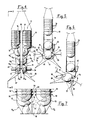
- the reference numeral 10 generally indicates the device, which is constituted by a metallic structure 11 which is intended to be suspended from the barycentric hook G of a helicopter E which, hovering in stationary flight above the overhead line LA, keeps said structure in the vertical plane which contains the cable C of the line which is to receive the marker balls P.
- the structure 11 comprises a first section 12 for containing the half-spheres 13 suitable for composing the balls P and a second section 14 for the positioning of the structure on the cable and the installation of the individual balls by juxtaposition and connection of corresponding pairs of half-spheres 13.
- Said half-spheres which are of a per se known type, are constituted by a hollow shell made of polymeric material and have cooperating snap-together coupling means, such as hooks and slots, or undercuts, preferably arranged on end sleeves 15 suitable for clamping the cable C as illustrated in detail in figure 3.
- the first section 12 of the structure 11 comprises two flanking magazines 16-17, each of which is dimensioned so as to store a plurality of half-spheres 13 arranged in a relationship of superimposition and orientated with their convex part downward; the capacity of said magazines depends on their height, which is generally comprised between 1000 and 1500 mm.
- the magazines 16 and 17 are separated by a central gap 18 which is open downward; the width of said gap is at least such as to allow the easy passage of the cable C or of old balls to be covered.
- the magazines In their lower portion, the magazines have respective funnel-shaped tapered regions 16a-17a which end with distribution channels 16b-17b.
- the half-spheres 13 undergo, due to the combined action of controlled retention elements which will be described hereinafter, a 90 o tilting so as to arrange themselves in facing pairs 13a-13b in the respective distribution channels 16b-17b, separated by the gap 18, as clearly illustrated in the figures.
- each distribution channel has vertical panels 16c-17c suitable for engaging the sleeves 15 of the half-spheres 13 to guide and retain them.
- the second section 14 of the structure 11 is arranged immediately below the distribution channels 16b-17b and is articulated to the first section 12 by means of a lateral hinge 19 which allows it to orientate itself in the vertical plane in which the cable C of the line is arranged.
- a fluid-actuated jack 20 the cylinder whereof is articulated to the first section and the stem whereof is articulated to the second section (or vice versa), actuates the rotation of said second section in said vertical plane.
- Two holder compartments 21-22 are formed in the section 14 for respective half-spheres arriving from the overlying distribution channels 16b-17b. Said compartments are open downward and have lateral horizontal panels 21a-22a on which the sleeves 15 of the half-spheres 13 abut in order to retain them.
- Respective presser elements furthermore extend into the compartments and are constituted by pairs of fluid-actuated jacks 23-24 suitable for pushing the facing half-spheres into mutual snap-together coupling, so that said half-spheres are closed onto the cable C, which as a consequence of the operative positioning of the structure is arranged inside the gap 18 at the diametrical axis of the facing half-spheres.
- two guiding and positioning notches 25 in the shape of an inverted V are formed on the opposite walls p1-p2 of the compartments 21-22 and are orthogonal to the plane of arrangement of the cable C; the vertex of said V, which is intended to abut on the cable, is substantially arranged at said diametrical axis of the half-spheres.
- a four-footed structure 26 which is composed of divaricated uprights and is used for the static resting of the device on the ground, extends below the compartments 21 and 22 and also defines a guiding channel 27 for the cable C which blends with the notches 25.
- Two opposite sensors 28-29 contribute to the operative positioning of the entire structure, are arranged at the respective vertices of the notches 25 and are supported, for example, by corresponding wings 30-31 of the four-footed structure 26.
- Circuit means associated with said sensors and not illustrated in the figure, activate an indication of correct positioning which is also transmitted to the cabin of the helicopter E, when both sensors are engaged by the cable C. In the line sections in which the cable is horizontal, this occurs with the jack 20 idle in retracted position and with the second section 14 of the structure aligned with the first section 12. If the cable portion involved in the installation of the ball is inclined, as illustrated for example in figure 6, contact occurs between a single sensor, for example the sensor 28, and the cable C.
- the passage of the half-spheres 13 from the respective magazine to the underlying distribution channel is controlled by a sensor which senses the presence of the half-spheres in the respective holder compartments 21-22; said sensor controls the distribution of new half-spheres into the holder compartments after a ball has been installed on the cable.
- each magazine has a set of three electromagnetic retention elements 32-33 and 34, which are constituted for example by known bolts actuated by respective solenoids.
- a pair 32-33 of said bolts is provided for the retention of the next to last half-sphere of the stack, whereas the third bolt 34 retains, in cooperation with a fixed stop element 35, the last half-sphere of the stack in a position which faces the distribution channel.
- said presence sensor for example constituted by a feeler 36, or by an optical photodiode-transistor pair, senses the absence of half-spheres in the compartments 21-22, it first of all actuates the opening of the bolt 34, which releases the last half-sphere of the stack, which, being retained by the fixed stop element 35, rotates about said stop element and arranges itself edge-on to enter the respective distribution channel, as is clearly illustrated in the figure 7.
- the bolt 34 returns to its stop position and provides the enabling signal for the opening of the bolts 32-33 which release the overlying stack of half-spheres, which moves downward and abuts on the bolt 34 and on the stop element 35 to allow the repetition of the controlled distribution cycle.
Landscapes
- Electric Cable Installation (AREA)
- Geophysics And Detection Of Objects (AREA)
Applications Claiming Priority (2)
| Application Number | Priority Date | Filing Date | Title |
|---|---|---|---|
| IT8967787A IT1235536B (it) | 1989-09-22 | 1989-09-22 | Dispositivo per la posa automatizzata,a mezzo di elicotteri,di palloni segnalatori su linee aeree,particolarmente elettrodotti in tensione |
| IT6778789 | 1989-09-22 |
Publications (2)
| Publication Number | Publication Date |
|---|---|
| EP0418751A2 true EP0418751A2 (fr) | 1991-03-27 |
| EP0418751A3 EP0418751A3 (en) | 1991-12-11 |
Family
ID=11305291
Family Applications (1)
| Application Number | Title | Priority Date | Filing Date |
|---|---|---|---|
| EP19900117746 Withdrawn EP0418751A3 (en) | 1989-09-22 | 1990-09-14 | Device for installing marker balls on overhead lines, particularly live power lines |
Country Status (3)
| Country | Link |
|---|---|
| US (1) | US5038465A (fr) |
| EP (1) | EP0418751A3 (fr) |
| IT (1) | IT1235536B (fr) |
Cited By (4)
| Publication number | Priority date | Publication date | Assignee | Title |
|---|---|---|---|---|
| WO1992019033A1 (fr) * | 1991-04-09 | 1992-10-29 | Saab Helikopter Aktiebolag | Dispositif et procede pour fournir un repere visuel d'une ligne ou d'un cable |
| NO20160899A1 (en) * | 2016-05-26 | 2017-11-27 | Mitta As | Device for visual marking |
| NO20190296A1 (en) * | 2019-03-04 | 2020-09-07 | Innova As | Device, system and method for installing an aircraft warning marker on a power line |
| EP4099524A1 (fr) | 2021-06-04 | 2022-12-07 | MS Design GmbH | Corps signalétique |
Families Citing this family (8)
| Publication number | Priority date | Publication date | Assignee | Title |
|---|---|---|---|---|
| US5210923A (en) * | 1989-12-29 | 1993-05-18 | Nichifu Terminal Manufacture Co., Ltd. | Method for attaching tabs to electric wire ends |
| USRE36333E (en) * | 1993-05-27 | 1999-10-12 | Kovaletz; Mark P. | Fixture apparatus for elevated lines |
| FR2740273B1 (fr) * | 1995-10-18 | 1997-11-21 | Electricite De France | Dispositif de pose de balises aeriennes sur un cable |
| CN112088127A (zh) * | 2018-03-07 | 2020-12-15 | 电网监控有限公司 | 使用飞行器在电缆上安装和拆卸设备的系统和方法 |
| CN112490928B (zh) * | 2020-11-12 | 2023-04-18 | 叶飞 | 基于无人机技术的高空配电架空线路带电作业方法及平台 |
| CN113070885A (zh) * | 2021-03-12 | 2021-07-06 | 国网浙江永康市供电有限公司 | 一种无人机搭载绝缘机械臂带电作业的方法 |
| US12408653B1 (en) * | 2022-01-13 | 2025-09-09 | John Paul Lethin | Bird diverter applicator that attaches bird diverters to power lines |
| US20230415928A1 (en) * | 2022-07-19 | 2023-12-28 | Alon Wallach | Warning Spheres Installation using Drones |
Family Cites Families (6)
| Publication number | Priority date | Publication date | Assignee | Title |
|---|---|---|---|---|
| US2829550A (en) * | 1956-08-21 | 1958-04-08 | Leonard B Hamshaw | Magazine fed hand tool for applying lead weights to fishing lines |
| US3374525A (en) * | 1965-10-14 | 1968-03-26 | Fabri Tek Inc | Component placement apparatus |
| US3430325A (en) * | 1966-06-27 | 1969-03-04 | Wesley G Lematta | Apparatus for securing warning markers to cables |
| US4377027A (en) * | 1980-08-01 | 1983-03-22 | Price Thomas J | Fishline sinker applicator |
| US4478312A (en) * | 1982-09-30 | 1984-10-23 | Kurtgis Michael P | System and portable cage for servicing power transmission lines |
| US4885835A (en) * | 1989-02-02 | 1989-12-12 | Osgood George M | Method of assembling line marker into suspended power line |
-
1989
- 1989-09-22 IT IT8967787A patent/IT1235536B/it active
-
1990
- 1990-09-14 EP EP19900117746 patent/EP0418751A3/en not_active Withdrawn
- 1990-09-17 US US07/583,127 patent/US5038465A/en not_active Expired - Fee Related
Cited By (6)
| Publication number | Priority date | Publication date | Assignee | Title |
|---|---|---|---|---|
| WO1992019033A1 (fr) * | 1991-04-09 | 1992-10-29 | Saab Helikopter Aktiebolag | Dispositif et procede pour fournir un repere visuel d'une ligne ou d'un cable |
| NO20160899A1 (en) * | 2016-05-26 | 2017-11-27 | Mitta As | Device for visual marking |
| NO20190296A1 (en) * | 2019-03-04 | 2020-09-07 | Innova As | Device, system and method for installing an aircraft warning marker on a power line |
| WO2020180190A1 (fr) * | 2019-03-04 | 2020-09-10 | Innova As | Dispositif, système et procédé d'installation d'un repère d'avertissement d'aéronef sur une ligne d'alimentation |
| NO346334B1 (en) * | 2019-03-04 | 2022-06-13 | Innova As | System and method for installing an aircraft warning marker on a power line |
| EP4099524A1 (fr) | 2021-06-04 | 2022-12-07 | MS Design GmbH | Corps signalétique |
Also Published As
| Publication number | Publication date |
|---|---|
| US5038465A (en) | 1991-08-13 |
| IT1235536B (it) | 1992-09-09 |
| IT8967787A0 (it) | 1989-09-22 |
| EP0418751A3 (en) | 1991-12-11 |
Similar Documents
| Publication | Publication Date | Title |
|---|---|---|
| US5038465A (en) | Device for installing marker balls on overhead cables, particularly live power cables | |
| US3688952A (en) | Spreader | |
| DE69205976T2 (de) | Einrichtung zur positionsangabe von einer leitung oder einem kabel. | |
| EP0143860B1 (fr) | Dispositif de préparation du fil de trame pour un métier à tisser multiphasé à foule linéaire | |
| EP0341434A3 (fr) | Dispositif et procédé pour tresser des torons de fibres | |
| CA2025776A1 (fr) | Dispositif pour l'installation de boules de balisage de lignes aeriennes, particulierement des lignes sous tension | |
| DE2742336C3 (de) | Verfahren und Vorrichtung zur Prüfung des Gewichtes von Behältern | |
| US5901435A (en) | Device for installing aerial beacons on a cable | |
| DE915915C (de) | Rohrpostanlage mit einer die ankommenden und abgehenden Fahrstraenge miteinander verbindenden vollselbsttaetigen Umladestelle | |
| GB2045119A (en) | Winding dynamoelectric machine stator coils | |
| DE3228469C2 (de) | Vorrichtung zur Stellungsanzeige an Schaltgeräten | |
| DE602004000721T2 (de) | Vorrichtung zum Transportieren einer Maschine zwischen mehreren Arbeitstationen | |
| EP0338301A1 (fr) | Dispositif d'alimentation en munitions | |
| US7028384B2 (en) | Method and device for processing cables | |
| EP0073956B1 (fr) | Dispositif de lutte contre l'incendie | |
| EP0468368B1 (fr) | Dispositif amélioré pour placer automatiquement, par hélicoptères, des boules de balisage sur des lignes aériennes, en particulier des lignes haute tension | |
| DE924259C (de) | Rohrpostanlage mit einer Umladestelle, welche die ankommenden und abgehenden Fahrstraenge durch eine Transporteinrichtung miteinander verbindet | |
| DE1760498B2 (de) | Zuführeinrichtung fur die Ablauf spulen an einer Textilmaschine | |
| DE2941950B1 (de) | Anordnung zur Signaluebertragung innerhalb eines Luftfahrzeuges | |
| GB776832A (en) | Improved means for storing and delivering rods, tubes and other long rigid articles | |
| US3123325A (en) | stephens | |
| US2360170A (en) | Conductor identifier | |
| CS200293B1 (en) | Monitoring and control system for weaving looms - with multiple sheds, minimises time lost in eliminating disturbances | |
| EP0148292A1 (fr) | Dispositif de contrôle du fil de trame pour métiers à tisser à foules en série | |
| DE639860C (de) | Foerderbandwaage |
Legal Events
| Date | Code | Title | Description |
|---|---|---|---|
| PUAI | Public reference made under article 153(3) epc to a published international application that has entered the european phase |
Free format text: ORIGINAL CODE: 0009012 |
|
| AK | Designated contracting states |
Kind code of ref document: A2 Designated state(s): AT CH DE DK ES FR GB LI SE |
|
| PUAL | Search report despatched |
Free format text: ORIGINAL CODE: 0009013 |
|
| AK | Designated contracting states |
Kind code of ref document: A3 Designated state(s): AT CH DE DK ES FR GB LI SE |
|
| 17P | Request for examination filed |
Effective date: 19920521 |
|
| 17Q | First examination report despatched |
Effective date: 19940530 |
|
| STAA | Information on the status of an ep patent application or granted ep patent |
Free format text: STATUS: THE APPLICATION IS DEEMED TO BE WITHDRAWN |
|
| 18D | Application deemed to be withdrawn |
Effective date: 19950124 |