EP0413659B2 - Installation having movable motorised rail guided units - Google Patents
Installation having movable motorised rail guided units Download PDFInfo
- Publication number
- EP0413659B2 EP0413659B2 EP90810591A EP90810591A EP0413659B2 EP 0413659 B2 EP0413659 B2 EP 0413659B2 EP 90810591 A EP90810591 A EP 90810591A EP 90810591 A EP90810591 A EP 90810591A EP 0413659 B2 EP0413659 B2 EP 0413659B2
- Authority
- EP
- European Patent Office
- Prior art keywords
- installation
- travelling
- accordance
- units
- parking
- Prior art date
- Legal status (The legal status is an assumption and is not a legal conclusion. Google has not performed a legal analysis and makes no representation as to the accuracy of the status listed.)
- Expired - Lifetime
Links
Images
Classifications
-
- E—FIXED CONSTRUCTIONS
- E04—BUILDING
- E04H—BUILDINGS OR LIKE STRUCTURES FOR PARTICULAR PURPOSES; SWIMMING OR SPLASH BATHS OR POOLS; MASTS; FENCING; TENTS OR CANOPIES, IN GENERAL
- E04H6/00—Buildings for parking cars, rolling-stock, aircraft, vessels or like vehicles, e.g. garages
- E04H6/42—Devices or arrangements peculiar to garages, not covered elsewhere, e.g. securing devices, safety devices, monitoring and operating schemes; centering devices
-
- E—FIXED CONSTRUCTIONS
- E04—BUILDING
- E04H—BUILDINGS OR LIKE STRUCTURES FOR PARTICULAR PURPOSES; SWIMMING OR SPLASH BATHS OR POOLS; MASTS; FENCING; TENTS OR CANOPIES, IN GENERAL
- E04H6/00—Buildings for parking cars, rolling-stock, aircraft, vessels or like vehicles, e.g. garages
- E04H6/08—Garages for many vehicles
- E04H6/12—Garages for many vehicles with mechanical means for shifting or lifting vehicles
- E04H6/30—Garages for many vehicles with mechanical means for shifting or lifting vehicles with means for transport in horizontal direction only
- E04H6/36—Garages for many vehicles with mechanical means for shifting or lifting vehicles with means for transport in horizontal direction only characterised by use of freely-movable dollies
Definitions
- the invention relates to a system with displaceable, rail-bound driving units according to the preamble of claim 1.
- a parking space can be optimally used when parking motor vehicles for parking on displaceable, rail-bound driving units, in particular parking platforms, as explained below in connection with FIG. 1 using an example.
- the drive of each parking platform has its own power supply with a flexible cable (hanging cable) hanging from the ceiling and rollers that can be moved on a rail, which leads to the drive motor through a vertical protective tube attached to the parking platform.
- This is a complex construction with complex electrical installation, particularly on numerous parking platforms.
- the protective tubes on the parking platforms are also annoying and are exposed to unsuitable parking.
- a car parking facility in which the vehicles are brought from the entrance to the parking lot and back by means of additional means of transportation.
- the vehicles are driven from a trolley to an empty parking lot, where the vehicle is driven from the trolley to the parking lot.
- the trolley is powered by electric motors and runs on rails.
- the current is drawn via a central, separate busbar.
- the transfer car is equipped with a control box that is operated from the operating platform.
- DE-37 40 684 A1 discloses a parking system with driven parking plates that can be moved on insulated rails.
- the parking plate drive units are controlled and powered by a modulated DC voltage applied to the rails. This DC voltage for supplying the drive unit is modulated as a function of a coded output signal from a microprocessor.
- the rails of the parking panels are mechanically and electrically insulated from the floor by means of an elastic insert.
- the rails are designed as a cylindrical full profile, which is slightly more than half taken up by an elastic and insulating holder.
- the elastic insert mentioned fills the inside of an upward-facing U-profile, which is completely sunk into the concrete floor. It is therefore essential to install the known rail before the floor covering is finished and to subsequently install the floor covering (concrete covering). In the event of retrofitting, the floor must be milled in, which is associated with considerable effort.
- a profile rail for small trolleys is known from DE-U 75 12 199.
- This has a flat central web M and two laterally drawn webs S. At their upper ends, the lateral webs S have outwardly drawn ends, the lower side of which forms a guide surface F.
- the trolley FW is, as it were, hooked to the rail in order to be able to overcome steep ramps or vertical sections if necessary.
- the wheels R are held from below against the guide surfaces F pointing upwards. They are each held by a bearing L encompassing the rail from the outside.
- a drive wheel A or a gear wheel Z rolls on the central web M.
- the FW tram has - in cross-section - three support points, namely two outer wheels (which engage the profile rail from below) and a drive wheel (which runs on the top of the rail).
- the object is achieved to create a system of the type mentioned, the construction and electrical installation is less expensive and has no disturbing damage-prone protective tubes or other protruding parts on the driving units.
- the rail foot of at least one rail of each track section has a lateral extension which expediently insulates from it or a plurality of mutually insulated, bare conductor tracks for drive and control current Driving units.
- the conductor track is expediently a conductor strip which extends continuously on the individual, butted rails of the track section and is simply fastened to the rail foot attachment by means of a continuous, self-adhesive plastic strip and is insulated from it.
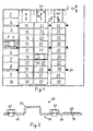
- the parking platforms 11 to 40 have a row of ten parking spaces 1 to 10 and three parallel rows of ten parking platforms 11 to 20, 21 to 30 and 31 to 40 and one next to the last row for a total of forty motor vehicles current entry and exit 42.
- the parking platforms of each three rows are on one track, eg 44, displaceable in the direction of arrow 46.
- the parking platforms 11 to 40 are equipped with rollers 50 running on the rails 48 of the relevant track section and with electric drive motors.
- the parking spaces 1 to 10 are, as usual, so wide that the distance between motor vehicles parked next to one another is sufficient to open the vehicle doors.
- the parking platforms 11 to 40 are narrower for the use of the area available for the system, with them the required lateral distance is achieved by displacing the parking platform.
- the parking platforms 31 to 40 can be reached directly at the entrance and exit 42.
- the lateral distance required for opening the motor vehicle doors from the platforms 35 and 37 is achieved by the platforms 31 to 35 being covered by a longer distance and the parking platform 36 by a shorter distance, based on FIG. 1 can be moved up.
- Each of the other parking platforms 11 to 30 and each of the parking spaces 1 to 10 can be made accessible for entry and exit 42 by moving parking platforms of the row or rows in front of them or the rows of parking platforms lying in front of the relevant parking space by an intermediate space clear for passage.
- a passage can be formed between the parking area 5 and the entrance and exit 42 by moving the platforms 11 to 14, 21 to 24 and 31 to 34 in FIG.
- the parking platform 26 can be made accessible from the entrance and exit 42 by moving the platforms 21 to 25 and 31 to 36 upwards by a longer distance and the platform 26 by a shorter distance in relation to FIG. 1. This applies starting from the starting position of the platforms 11 to 40 shown in FIG. 1 and analogously for other starting positions.
- 54 are support pillars which support a ceiling (not shown) of the installation if it is constructed underground. Since the parking platforms can be moved, the support pillars 54 do not form any obstacles.
- An electronic data processing device assigns a free parking space or a free parking platform to each arriving vehicle and controls the drives or couplings of the platforms that have to be moved in order to access the assigned parking space or the assigned platform with the required lateral distance from the neighboring platforms do.
- This electronic data processing device is not shown and is not the subject of the invention.
- At least one bare conductor track 60 for the drive and control current of the parking platforms 11 to 20 and 21 runs in the system according to the invention, for example with parking platforms 11 to 40 to 30 and 31 to 40, respectively, and the parking platforms have current collectors 61 which are held in contact with the conductor track or tracks 60.
- At least one of the rails can form a further conductor track, in particular a common return line, for drive and control current.
- the control current can be an alternating current, in particular pulse-coded, superimposed on the drive current.
- the conductor track is appropriately band-shaped.
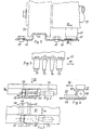
- the head 63 of a rail 48 is formed by an inverted U-shaped bulge of a steel sheet 64, the legs 65, 66 of which are angled outwards to form a Schlenen pass and fastened to the bottom 68 by means of screws 67 (see FIGS. 5 and 6) are.
- the leg or flange 66 is wider than the leg or flange 65 and carries the conductor track 60 consisting of a metal strip with an insulating intermediate layer 70 glued to the flange 66.
- the use of a metal strip enables a relatively large contact area with the current collector.
- Fastening by gluing is very simple and avoids fastening means projecting beyond the upper surface of the conductor track, so that the entire upper surface of the metal strip can be used for contact with the current collector. It is particularly expedient to glue the metal strip to the flange 66 by means of a plastic strip 70 which is self-adhesive on both sides.
- the metal band forming the conductor track 60 and the plastic band 70 continuously extend all the way Length of the rail track consisting of individual butted rails, i.e. across the joints.
- Several such conductor tracks can be arranged distributed on one and the same flange 66 or on both flanges 65 and 66, with correspondingly arranged current collectors being provided on the platforms.
- the current collector 61 shown in FIGS. 3 and 4 has two contact pieces 73, 74 (not shown) resiliently pressed against the conductor track 60, which are arranged between two strippers 76 and 77 which are resiliently pressed against the conductor track 60 and which serve foreign objects and wipe off contaminants in both directions so that they do not prevent the current draw.
- the drive motor is a gear motor 79/80 (motor 79, gear 80) with an output shaft 81 coaxial with the motor shaft, on which the roller 50 is seated.
- the gearbox is expediently a planetary gearbox with such a ratio that the platforms can be moved by hand in the event of a power failure (the gearbox is therefore not self-locking), so that the system does not fail if the power supply malfunctions or the mentioned (not shown) data processing device fails blocked, but still if it is difficult to use.
- the parking platforms are not displaceable transversely, as in FIG. 1, but longitudinally (that is to say in the direction of travel of the motor vehicle traveling to and from the platform), they must be equipped with a brake which is released when the drive is switched on. Without such a brake, a motor vehicle that starts to drive onto a platform or to leave a platform could push it away. So that the platforms can be moved by hand if necessary (in the event of a power supply or data processing device failure), these brakes can also be operated and released by hand. If the drive acts on one or more rollers of the parking platform, it is usually not enough to brake them, because the friction between rollers and rails is relatively low, at least when the platform is not under load.
- the brake can also be designed as a magnetic brake.
- Another embodiment has one or more pairs of jaws, the jaws of which are pressed against the facing or facing away sides (web sides) of the two rails.
- Driving units equipped with such a brake could also supply the drive and control current in a fundamentally different manner than that shown, for example, in FIGS. 2 and 3.
- the drive motor 79/80 with the roller 50 is accommodated in a box-like extension 84 on one of the edges perpendicular to the direction of displacement 46 of the platform, which at the same time forms a wheel deflector for the motor vehicle to be parked on the surface 85 of the platform.
- the drive and control current could also be supplied in a manner which is in principle different from that shown, for example, in FIGS. 2 and 3.
- a control device (not shown) contains an on / off and reversing switch for the motor 79 in order to control it in accordance with signals supplied by the data processing device.
- the driving units are parking platforms on which motor vehicles are parked for parking
- a parking platform can, for example, hit a piece of luggage that has fallen onto the road from a motor vehicle parked for parking, or collide with a person who negligently entered the road.
- z. B each parking platform on the sides perpendicular to their direction of displacement one actuatable by an obstacle, z. B. in the form of the usual in motor vehicles, but differently resiliently held bumper, which triggers an electrical signal when giving in. If the signal z. B.
- the light beam of a light barrier that drives the drive current of the parking platforms when the light beam is interrupted switches off and interrupts the program sequence so that the system must be switched on again after the fault has been rectified to continue the program.
- the light beam can, for example, first run between the rows of parking platforms 11 to 20 and 21 to 30 and then be deflected by 90 ° at two mirrors and finally run on the left side of the row of parking platforms 31 to 40 in FIG. 1.
- two or three light barriers each associated with a row of parking platforms, could also be provided, with the emergency stop having to be triggered when the light beam is interrupted by one of these light barriers.
- the emergency stop having to be triggered when the light beam is interrupted by one of these light barriers.
- only the drive current for the relevant row of parking platforms could be switched off.
- each parking platform is equipped with one or two apertures, e.g. B. in the form of flaps, each of which is movable from an inactive rest position into an effective position in which it interrupts the light beam, for. B. is pivotable.
- an organ similar to a motor vehicle bumper, extends but resiliently held on each of the sides of the parking platforms that are perpendicular to its direction of displacement, the organ of which yields when the bumper hits an obstacle moved into their impact situation.
- the diaphragm can be held in its rest position by a pawl or a bolt against the force of a spring which tends to move the diaphragm into its operative position, and the pawl or bolt can be released by the yielding movement of the organ.
- a gear is provided which converts the yielding movement of the organ into the movement of the diaphragm, which leads to its operative position.
- the organ can e.g. B. also be a flap protruding in its rest position, suspended on a horizontal axis, on which a return spring acts.
- a diaphragm is expediently assigned to each of these organs.
- both organs could also be assigned a diaphragm together, which can be moved into their operative position both by the yielding effect of one and by the other organ.
- the parking platforms each have one or two customary buffers on the sides perpendicular to their direction of displacement, which ensure a minimum distance between successive parking platforms. At this distance, the mutually facing organs (of the type mentioned) of the two parking platforms should not yet touch each other.
- this light-electric safety device is not only suitable for the system according to the invention but generally for systems with driving units which are tied to a predetermined, essentially straight movement path.
Abstract
Description
Die Erfindung bezieht sich auf eine Anlage mit verschiebbaren, schienengebundenen Fahreinheiten gemäss Oberbegriff des Anspruchs 1.The invention relates to a system with displaceable, rail-bound driving units according to the preamble of claim 1.
Es ist bekannt, dass eine Parkfläche optimal ausgenutzt werden kann, wenn Kraftfahrzeuge zum Parkieren auf verschiebbaren, schienengebundenen Fahreinheiten, namentlich Parkplattformen, abgestellt werden, wie nachstehend im Zusammenhang mit Figur 1 an einem Beispiel erläutert. Bei üblichen Anlagen dieser Art hat der Antrieb jeder Parkplattform eine eigene Stromzuführung mit einer an der Decke, an einer Schiene verfahrbaren Rollen hängenden, flexiblen Leitung (Hängekabel), die durch ein an der Parkplattform befestigtes, vertikales Schutzrohr zum Antriebsmotor führt. Das ist eine besonders bei zahlreichen Parkplattformen aufwendige Konstruktion mit aufwendiger elektrischer Installation. Auch sind die Schutzrohre an den Parkplattformen störend und bei ungeschicktem Parkieren Beschädigungen ausgesetzt Das ist auch dann der Fall, wenn nur eine oder einige der Parkplattformen des oder jedes Gleisstranges mit einem Antriebsmotor und die anderen Plattformen je mit einer fernsteuerbaren Kupplung, zu der ein Hängekabel führt, ausgerüstet sind, um von einer angetriebenen Plattform gezogen (und gestossen) zu werden. In diesem Fall genügt die Haftreibung zwischen angetriebenen Laufrollen der angetriebenen Plattform und den Schienen, wenn kein Kraftfahrzeug auf ihr steht, nicht zum Verschieben, weshalb beispielsweise eine Kette auf dem Boden oder in einer Aussparung desselben vorgesehen wird, die über ein angetriebenes Kettenrad der mit dem Antrieb ausgerüsteten Plattform geführt ist.It is known that a parking space can be optimally used when parking motor vehicles for parking on displaceable, rail-bound driving units, in particular parking platforms, as explained below in connection with FIG. 1 using an example. In conventional systems of this type, the drive of each parking platform has its own power supply with a flexible cable (hanging cable) hanging from the ceiling and rollers that can be moved on a rail, which leads to the drive motor through a vertical protective tube attached to the parking platform. This is a complex construction with complex electrical installation, particularly on numerous parking platforms. The protective tubes on the parking platforms are also annoying and are exposed to unsuitable parking. This is also the case if only one or some of the parking platforms of the or each track section with a drive motor and the other platforms each with a remote-controlled coupling to which a suspension cable leads , are equipped to be pulled (and pushed) from a powered platform. In this case, the static friction between the driven rollers of the driven platform and the rails, when there is no motor vehicle on them, is not sufficient for displacement, which is why, for example, a chain is provided on the floor or in a recess thereof, which is connected via a driven sprocket to the Drive equipped platform is guided.
Es ist auch bekannt, Parkplattformen durch ganz oder teilweise in Aussparungen des Bodens untergebrachte Antriebsvorrichtungen zu verschieben. Dabei ist die mögliche Verschiebungsstrecke relativ kurz, der Einbau in den Boden, der ein Entwässerungsgefälle und Entwässerungsleitungen erfordert, aufwendig, bei einem bereits bestehenden Gebäude in der Regel nicht mehr möglich und in jedem Falle aufwendig. Auch bedürfen solche Anlagen mehr Wartungsaufwand.It is also known to move parking platforms by wholly or partially housed drive devices in recesses in the floor. The possible displacement distance is relatively short, the installation in the ground, which requires a drainage gradient and drainage pipes, is complex, is usually no longer possible in an existing building and is complex in any case. Such systems also require more maintenance.
Aus der US-A-2 598 750 ist eine Autoparkanlage bekannt, bei welcher die Fahrzeuge mittels zusätzlicher Transportmittel von der Zufahrt zum Parkplatz und zurück gebracht werden. In einem vorzugsweise mehrstöckigen Parkhaus werden die Fahrzeuge von einem Transportwagen zu einem leeren Parkplatz gefahren, wo das Fahrzeug vom Transportwagen auf den Parkplatz gefahren wird. Der Transportwagen wird durch elektrische Motoren angetrieben und läuft auf Schienen. Die Stromaufnahme erfolgt über eine zentrale separate Stromschiene. Der Transferwagen ist mit einem Steuerkasten ausgerüstet, der von der Bedienungsplattform her bedient wird. Der Nachteil dieser Anlage besteht darin, dass das Versorgen und Herausholen eines Fahrzeuges ziemlich aufwendig ist.From US-A-2 598 750 a car parking facility is known in which the vehicles are brought from the entrance to the parking lot and back by means of additional means of transportation. In a preferably multi-storey car park, the vehicles are driven from a trolley to an empty parking lot, where the vehicle is driven from the trolley to the parking lot. The trolley is powered by electric motors and runs on rails. The current is drawn via a central, separate busbar. The transfer car is equipped with a control box that is operated from the operating platform. The disadvantage of this system is that supplying and removing a vehicle is quite complex.
Aus der DE-37 40 684 Al ist ein Parksystem mit auf isolierten Fahrschienen verfahrbaren, angetriebenen Parkplatten bekannt. Die Steuerung und Speisung der Parkplattenantriebsaggregate erfolgt durch eine an die Schienen angelegte modulierte Gleichspannung. Diese Gleichspannung zur Versorgung des Antriebsaggregats wird in Abhängigkeit von einem codierten Ausgangssignal eines Mikroprozessors moduliert. Die Fahrschienen der Parkplatten sind vom Boden mittels einer elastischen Einlage mechanisch und elektrisch isoliert. Die Schienen sind als zylindrisches Vollprofil ausgebildet, das etwas mehr als zur Hälfte durch eine elastische und isolierende Halterung aufgenommen wird. Die genannte elastische Einlage füllt das Innere eines nach oben weisenden U-Profils aus, welches vollständig im Betonboden versenkt ist. Es ist also unumgänglich, die bekannte Schiene vor Fertigstellung des Bodenbelags zu montieren und den Bodenbelag (Betonüberzug) nachträglich anzubringen. Im Fall eines nachträglichen Einbaus muss der Boden eingefräst werden, was mit einem beträchtlichen Aufwand verbunden ist.DE-37 40 684 A1 discloses a parking system with driven parking plates that can be moved on insulated rails. The parking plate drive units are controlled and powered by a modulated DC voltage applied to the rails. This DC voltage for supplying the drive unit is modulated as a function of a coded output signal from a microprocessor. The rails of the parking panels are mechanically and electrically insulated from the floor by means of an elastic insert. The rails are designed as a cylindrical full profile, which is slightly more than half taken up by an elastic and insulating holder. The elastic insert mentioned fills the inside of an upward-facing U-profile, which is completely sunk into the concrete floor. It is therefore essential to install the known rail before the floor covering is finished and to subsequently install the floor covering (concrete covering). In the event of retrofitting, the floor must be milled in, which is associated with considerable effort.
Aus der DE-U 75 12 199 ist eine Profilschiene für kleine Förderwagen bekannt. Diese weist einen flachen Mittelsteg M und zwei seitlich nach oben gezogene Stege S auf. An ihren oberen Enden haben die seitlichen Stege S nach aussen gezogene Enden, deren untere Seite eine Führungsfläche F bildet. Der Förderwagen FW ist mit der Schiene gleichsam verhakt, um gegebenenfalls auch Steilrampen bzw. vertikale Wegstücke überwinden zu können. Die Räder R werden von unten an die nach oben weisenden Führungsflächen F gehalten. Sie sind jeweils von einer die Schiene von aussen umgreifenden Lagerung L gehalten. Auf dem Mittelsteg M rollt ein Antriebsrad A bzw. ein Zahnrad Z ab. Der Förderwagen FW hat - im Querschnitt betrachtet - drei Abstützpunkte, nämlich zwei äussere Räder (die von unten an der Profilschiene angreifen) und ein Antriebsrad (welches auf der Schienenoberseite läuft).A profile rail for small trolleys is known from DE-U 75 12 199. This has a flat central web M and two laterally drawn webs S. At their upper ends, the lateral webs S have outwardly drawn ends, the lower side of which forms a guide surface F. The trolley FW is, as it were, hooked to the rail in order to be able to overcome steep ramps or vertical sections if necessary. The wheels R are held from below against the guide surfaces F pointing upwards. They are each held by a bearing L encompassing the rail from the outside. A drive wheel A or a gear wheel Z rolls on the central web M. The FW tram has - in cross-section - three support points, namely two outer wheels (which engage the profile rail from below) and a drive wheel (which runs on the top of the rail).
Durch die Erfindung, wie sie im Patentanspruch 1 gekennzeichnet ist, die Aufgabe gelöst, eine Anlage der eingangs genannten Art zu schaffen, deren Konstruktion und elektrische Installation weniger aufwendig ist und keine störenden beschädigungsanfälligen Schutzrohre oder andere an den Fahreinheiten vorstehende Teile hat.By the invention, as characterized in claim 1, the object is achieved to create a system of the type mentioned, the construction and electrical installation is less expensive and has no disturbing damage-prone protective tubes or other protruding parts on the driving units.
Die durch die Erfindung erzielten Vorteile sind im wesentlichen darin zu sehen, dass die Konstruktion und die elektrische Installation der erfindungsgemässen Anlage viel weniger aufwendig ist, dass die Fahreinheiten keine störende, vorstehende, Beschädigungen ausgesetzte Teile haben, und dass die Anlage keine Teile hat, die in Aussparungen des Bodens mit Entwässerungsgefälle und Entwässerungsleitungen eingebaut werden müssen, was bei bereits bestehenden Gebäuden meist nicht mehr möglich ist. Ein weiterer Vorteil ist der geringere Wartungsaufwand.The advantages achieved by the invention are essentially to be seen in the fact that the construction and the electrical installation of the system according to the invention is much less complex, that the driving units have no disruptive, protruding parts exposed to damage, and that the system has no parts that must be installed in recesses in the floor with drainage gradients and drainage pipes, which is usually no longer possible with existing buildings. Another advantage is the lower maintenance effort.
Besonders einfach zu montieren und nicht störend im Betrieb der Anlage ist eine Ausführungsart der Erfindung, bei welcher der Schienenfuss wenigstens einer Schiene jedes Gleisstranges einen seitlichen Ansatz hat, der eine zweckmässig von ihm isolierte oder mehrere voneinander isolierte, blanke Leiterbahnen für Antriebs- und Steuerstrom der Fahreinheiten trägt. Dabei ist die Leiterbahn zweckmässig ein Leiterband, das sich fortlaufend an den einzelnen, gestossenen Schienen des Gleisstranges erstreckt und einfach mittels eines fortlaufenden, an beiden Seiten selbstklebenden Kunststoffbandes am Schienenfussansatz befestigt und dabei von diesem isoliert ist. Diese und weitere Aussführungsarten der Erfindung, durch die weitere Aufgaben gelöst und Vorteile erzielt werden, sind in den abhängigen Patentansprüchen angegeben und nachstehend näher beschrieben.Particularly easy to assemble and not disruptive in the operation of the system is an embodiment of the invention, in which the rail foot of at least one rail of each track section has a lateral extension which expediently insulates from it or a plurality of mutually insulated, bare conductor tracks for drive and control current Driving units. The conductor track is expediently a conductor strip which extends continuously on the individual, butted rails of the track section and is simply fastened to the rail foot attachment by means of a continuous, self-adhesive plastic strip and is insulated from it. These and other embodiments of the invention, by means of which further objects are achieved and advantages are achieved, are specified in the dependent patent claims and are described in more detail below.
Im folgenden wird die Erfindung anhand der beiliegenden, nur einen Ausführungsweg darstellenden Zeichnungen am Beispiel einer erfindungsgemässen Parkieranlage näher erläutert. Es zeigen:
- Fig. 1
- einen schematischen Grundriss einer Parkieranlage bekannter Art,
- Fig. 2
- einen Querschnitt einer Schiene einer nach der Erfindung ausgeführten Anlage der an sich bekannterArt nach Fig. 1, mit einer Stromzuführung für Antriebs- und/oder Steuerstrom für auf ihr verschiebbare Parkplattformen (Schnitt II-II in Fig. 1),
- Fig. 3
- einen Schnitt einer Schiene nach Fig. 2 zusammen mit einer auf ihr rollenden Rolle einer Parkplattform und einem Stromabnehmer derselben,
- Fig. 4
- einen teilweisen Schnitt des Stromabnehmers nach der Linie IV-IV in Fig. 3, mit zwei Abstreifern,
- Fig. 5
- eine der Fig. 3 entsprechende Ansicht mit weiteren Teilen der Parkplattform, in kleinerem Massstab,
- Fig. 6
- eine Ansicht In Blickrichtung VI in Fig. 5 und
- Fig. 7
- eine Draufsicht In Blickrichtung VII in Fig. 5.
- Fig. 1
- a schematic floor plan of a parking system of known type,
- Fig. 2
- a cross section of a rail of a system according to the invention of the type known per se according to Fig. 1, with a power supply for drive and / or control current for displaceable on it Parking platforms (section II-II in Fig. 1),
- Fig. 3
- 3 shows a section of a rail according to FIG. 2 together with a roller of a parking platform and a current collector of the same,
- Fig. 4
- 3 shows a partial section of the pantograph along the line IV-IV in FIG. 3, with two wipers,
- Fig. 5
- 3 corresponding view with other parts of the parking platform, on a smaller scale,
- Fig. 6
- a view in viewing direction VI in Fig. 5 and
- Fig. 7
- 5 shows a plan view in viewing direction VII in FIG. 5.
Die Anlage zum Parkieren von Kraftfahrzeugen nach Fig. 1 hat für insgesamt vierzig Kraftfahrzeuge eine Reihe von zehn Parkfeldern 1 bis 10 und drei zu dieser parallele Reihen von je zehn Parkplattformen 11 bis 20, 21 bis 30 und 31 bis 40 sowie eine neben der letzten Reihe verlaufende Zu- und Wegfahrt 42. Die Parkplattformen jeder drei Reihen sind auf einem Gleisstrang, z.B. 44, in Pfeilrichtung 46 verschiebbar. Dazu sind die Parkplattformen 11 bis 40 mit auf den Schienen 48 des betreffenden Gleisstranges laufenden Laufrollen 50 und mit elektrischen Antriebsmotoren ausgerüstet Die Parkfelder 1 bis 10 sind wie üblich so breit, dass der Abstand nebeneinander parkierter Kraftfahrzeuge zum Oeffnen der Fahrzeugtüren ausreicht. Die Parkplattformen 11 bis 40 sind zur Nutzung der für die Anlage zur Verfügung stehenden Fläche schmäler, bei ihnen wird der erforderliche seitliche Abstand durch Parkplattform-Verschiebungen erzielt Die Parkplattformen 31 bis 40 sind an der Zu- und Wegfahrt 42 unmittelbar erreichbar. Beispielsweise zum Parkieren auf oder Wegfahren von der Parkplattform 36 wird der zum Oeffnen der Kraftfahrzeugtüren erforderliche seitliche Abstand von den Plattformen 35 und 37 erreicht, indem die Plattformen 31 bis 35 um eine längere Strecke und die Parkplattform 36 um eine kürzere Strecke, bezogen auf Fig. 1 nach oben verschoben werden. Jede der anderen Parkplattformen 11 bis 30 und jedes der Parkfekfelder 1 bis 10 kann zur Zu- und Wegfahrt 42 zugänglich gemacht werden, indem Parkplattformen der vor ihr liegenden Reihe oder Reihen bzw. der vor dem betreffenden Parkplatz liegenden Reihen Parkplattformen verschoben werden, um einen Zwischenraum zur Durchfahrt freizugeben. Beispielsweise kann eine Durchfahrt zwischen dem Parkfeld 5 und der Zu- und Wegfahrt 42 gebildet werden, indem die Plattformen 11 bis 14, 21 bis 24 und 31 bis 34 in Fig. 1 (bezogen auf die Zeichnung) nach oben verschoben werden. Ebenso kann die Parkplattform 26 von der Zu- und Wegfahrt 42 zugänglich gemacht werden, indem die Plattformen 21 bis 25 und 31 bis 36 um eine längere Strecke und die Plattform 26 um eine kürzere Strecke bezogen auf Fig. 1, nach oben verschoben werden. Dies gilt aus gehend von der in Fig. 1 dargestellten Ausgangslage der Plattformen 11 bis 40 und sinngemäss bei anderen Ausgangslagen. 54 sind Stützsäulen, welche eine nicht dargestellte Decke der Anlage tragen, wenn diese unterirdisch ausgeführt ist Da die Parkplattformen verschiebbar sind, bilden die Stützsäulen 54 keine Hindernisse.1 has a row of ten parking spaces 1 to 10 and three parallel rows of ten
Eine elektronische Datenverarbeltungseinrichtung weist jedem ankommenden Fahrzeug ein freies Parkfeld oder eine freie Parkplattform zu und steuert die Antriebe bzw. Kupplungen der Plattformen, die verschoben werden müssen, um das zugewiesene Parkfeld oder die zugewiesene Plattform mit dem erforderlichen seitlichen Abstand von den ihr benachbarten Plattformen zugänglich zu machen. Diese elektronische Datenverarbeitungseinrichtung ist nicht dargestellt und nicht Gegenstand der Erfindung.An electronic data processing device assigns a free parking space or a free parking platform to each arriving vehicle and controls the drives or couplings of the platforms that have to be moved in order to access the assigned parking space or the assigned platform with the required lateral distance from the neighboring platforms do. This electronic data processing device is not shown and is not the subject of the invention.
Wenn die im Zusammenhang mit Fig. 1 beschriebene Anlage in der bisher üblichen Weise mit Hängeleitungen und an jeder Plattform mit einem vertikalen, fast zwei Meter hohen Schutzrohr für den nach unten führenden Leitungsteil für den Antriebsstrom bzw. Steuerstrom der Kupplung ausgeführt ist, bedarf es, dreissig Hängeleitungen und dreissig vertikaler, die abwärtsführenden Leitungsteile aufnehmender Schutzrohre.If the system described in connection with FIG. 1 is designed in the usual way with hanging lines and on each platform with a vertical, almost two meter high protective tube for the downward line part for the drive current or control current of the coupling, thirty suspension lines and thirty vertical protective tubes that receive the downward line parts.
Bei der erfindungsgemässen, beispielsweise mit Parkplattformen 11 bis 40 ausgeführten Anlage nach Fig. 1 und 2 bis 6 verläuft neben einer oder jeder der beiden Schienen 48 jedes Gleisstranges 44 wenigstens eine blanke Leiterbahn 60 für Antriebs- und Steuerstrom der Parkplattformen 11 bis 20 bzw. 21 bis 30 bzw. 31 bis 40, und die Parkplattformen haben Stromabnehmer 61, die in Kontakt mit der oder den Leiterbahnen 60 gehalten sind.1 and 2 to 6, in addition to one or each of the two
Zusätzlich kann wenigstens eine der Schienen eine weitere Leiterbahn, insbesondere eine gemeinsame Rückleitung, für Antriebs- und Steuerstrom bilden. Der Steuerstrom kann ein dem Antriebsstrom überlagerter, insbesondere impulscodierter Wechselstrom sein. Die Leiterbahn ist zweckmässig bandförmig.In addition, at least one of the rails can form a further conductor track, in particular a common return line, for drive and control current. The control current can be an alternating current, in particular pulse-coded, superimposed on the drive current. The conductor track is appropriately band-shaped.
Nach Fig. 2 ist der Kopf 63 einer Schiene 48 durch eine umgekehrt U-förmige Ausbuchtung eines Stahlbleches 64 gebildet, deren Schenkel 65, 66 zur Bildung eines Schlenenpasses nach aussen abgewinkelt und mittels Schrauben 67 am Boden 68 befestigt (vgl. Fig. 5 und 6) sind. Der Schenkel oder Flansch 66 ist breiter als der Schenkel oder Flansch 65 und trägt die aus einem Metallband bestehende Leiterbahn 60 mit einer isolierenden Zwischenschicht 70 an den Flansch 66 geklebt Die Verwendung eines Metallbandes ermöglicht eine relativ grosse Kontaktfläche mit dem Stromabnehmer. Die Befestigung durch Kleben ist sehr einfach, und vermeidet die obere Fläche der Leiterbahn überragende Befestigungsmittel, so dass die ganze obere Fläche des Metallbandes zum Kontakt mit dem Stromabnehmer nutzbar ist. Besonders zweckmässig ist es, das Metallband mittels eines an beiden Seiten selbstklebenden Kunststoffbandes 70 an den Flansch 66 zu kleben. Das die Leiterbahn 60 bildende Metallband und das Kunststoffband 70 erstrecken sich fortlaufend an der ganzen Länge des aus einzelnen gestossenen Schienen bestehenden Schienenstranges, also über die Stossstellen hinweg. Mehrere solche Leiterbahnen können auf ein und demselben Flansch 66 oder auf beide Flansche 65 und 66 verteilt angeordnet werden, wobei entsprechend angeordnete Stromabnehmer an den Plattformen vorzusehen sind.2, the
Der aus Fig. 3 und 4 ersichtliche Stromabnehmer 61 hat zwei (in nicht dargestellter Weise) nachgiebig an die Leiterbahn 60 gedrückte Kontaktstücke 73, 74, die zwischen zwei nachgiebig an die Leiterbahn 60 gedrückten Abstreifern 76 und 77 angeordnet sind, welche dazu dienen, Fremdkörper und Verunreinigungen sowohl in der einen als auch in der anderen Fahrrichtung abzustreifen, damit diese die Stromabnahme nicht hindern.The
Nach Fig. 5 bis 7 ist der Antriebsmotor ein Getriebemotor 79/80 (Motor 79, Getriebe 80) mit zur Motorwelle koaxialer Abtriebswelle 81, auf der die Laufrolle 50 sitzt. Dabei ist das Getriebe zweckmässig ein Planetengetriebe mit einer solchen Uebersetzung, dass die Plattformen bei Stromausfall von Hand verschoben werden können (das Getriebe also nicht selbsthemmend ist), damit die Anlage bei einer Störung der Stromversorgung oder beim Versagen der erwähnten (nicht dargestellten) Datenverarbeitungseinrichtung nicht blockiert, sondern immer noch, wenn auch umständlich benutzbar ist.5 to 7, the drive motor is a
Wenn die Parkplattformen nicht wie in Fig. 1 quer, sondern längs (also in Fahrrichtung des auf die Plattform und von dieser weg fahrenden Kraftfahrzeugs) verschiebbar sind, müssen sie mit einer Bremse ausgerüstet werden, die bei eingeschaltetem Antrieb gelöst ist. Ohne eine solche Bremse könnte ein Kraftfahrzeug, das zum Auffahren auf eine Plattform oder zum Verlassen einer Plattform ansetzt, diese wegschieben. Damit die Plattformen erforderlichenfalls (bei Ausfall der Stromversorgung oder der Datenverarbeitungseinrichtung) von Hand verschoben werden können, sind diese Bremsen auch von Hand betätigbar und lösbar. Wenn der Antrieb auf eine oder mehrere Laufrollen der Parkplattform wirkt, genügt es in der Regel nicht, diese zu bremsen, denn die Reibung zwischen Laufrollen und Schienen ist mindestens bei unbelasteter Plattform relativ gering. Zweckmässig ist eine am Schienenkopf oder -fuss oder zangenartig am Schienensteg oder am rauhen (Beton-) Boden der Anlage grossflächig angreifende Bremse mit Reibbelag. Die Bremse kann auch als Magnetbremse ausgeführt sein. Eine andere Ausführungsart hat eine oder mehrere Backen paare, deren Backen an die einander zugewandten oder an die einander abgewandten Seiten (Stegseiten) der beiden Schienen gepresst werden. Mit einer solchen Bremse ausgerüsteten Fahreinheiten könnte der Antriebs- und Steuerstrom auch auf eine grundsätzlich andere als die beispielsweise in Fig. 2 und 3 dargestellte Weise zugeführt werden.If the parking platforms are not displaceable transversely, as in FIG. 1, but longitudinally (that is to say in the direction of travel of the motor vehicle traveling to and from the platform), they must be equipped with a brake which is released when the drive is switched on. Without such a brake, a motor vehicle that starts to drive onto a platform or to leave a platform could push it away. So that the platforms can be moved by hand if necessary (in the event of a power supply or data processing device failure), these brakes can also be operated and released by hand. If the drive acts on one or more rollers of the parking platform, it is usually not enough to brake them, because the friction between rollers and rails is relatively low, at least when the platform is not under load. It is advisable to have a large-area brake with friction lining on the rail head or foot or pliers-like on the rail web or on the rough (concrete) floor of the system. The brake can also be designed as a magnetic brake. Another embodiment has one or more pairs of jaws, the jaws of which are pressed against the facing or facing away sides (web sides) of the two rails. Driving units equipped with such a brake could also supply the drive and control current in a fundamentally different manner than that shown, for example, in FIGS. 2 and 3.
Nach Fig. 5 bis 7 ist der Antriebsmotor 79/80 mit der Laufrolle 50 in einem kastenartigen Ansatz 84 an einem der zur Verschiebungsrichtung 46 der Plattform rechtwinkligen Rändern untergebracht, der gleichzeitig einen Radabweiser für das auf der Fläche 85 der Plattform abzustellende Kraftfahrzeug bildet. Bei dieser Anordnung des Antriebsmotors könnte der Antriebs- und Steuerstrom auch auf eine im Prinzip andere als die beispielsweise in Fig. 2 und 3 dargestellte Weise zugeführt werden.5 to 7, the
Ein nicht dargestelltes Steuergerät enthält einen Ein/Aus- und Wendeschalter für den Motor 79, um diesen entsprechend von der Datenverarbeitungseinrichtung gelieferter Signale zu steuern.A control device (not shown) contains an on / off and reversing switch for the
In Fig. 2 bis 7 ist angenommen, dass ein Antriebsgleichstrom und Steuerwechselstrom mit für Start, Stopp und die beiden Drehrichtungen unterschiedlichen Impulsfolgen durch die Leiterbahn 60 zugeführt werden, und dass die Schienen 48 zur Rückleitung des Antriebs- und Steuerstromes dienen. Mittel zur Trennung von Gleichund Wechselstrom und zur Steuerung mittels verschiedener Impulsfolgen sind bekannt.2 to 7 it is assumed that a direct drive current and alternating control current with different pulse trains for start, stop and the two directions of rotation are supplied through the
Indem mehrere Leiterbahnen 60 an einer Schiene vorgesehen oder auf beide Schienen jedes Schienenstranges verteilt angeordnet werden, ergeben sich zahlreiche Möglichkeiten für die Zuführung des Antriebsund des Steuerstromes mit Rückleitung durch die eine, die andere oder beide Schienen, mit Rückleitung durch eine Leiterbahn, mit getrennter Zuführung des Antriebs- und des Steuerstromes oder mit Ueberlagerung, wie erwähnt.By providing a plurality of conductor tracks 60 on one rail or arranging them on both rails of each rail track, there are numerous possibilities for supplying the drive and control current with return through one, the other or both rails, with return through a conductor, with separate supply the drive and control current or with superimposition, as mentioned.
Bei Anlagen vorliegender Art kann es erwünscht oder notwendig sein, den Antriebsstrom für eine oder alle Fahreinheiten automatisch abzuschalten, sobald eine Fahreinheit an ein Hindernis stösst. Wenn die Fahreinheiten, wie im vorstehend beschriebenen Ausführungsbeispiel der erfindungsgemässen Anlage, Parkplattformen sind, auf denen Kraftfahrzeuge zum Parkieren abgestellt werden, kann eine Parkplattform etwa an ein GepäckstücK das von einem zum Parkieren abgestellten Kraftfahrzeug auf die Fahrbahn gefallen ist, anstossen oder mit einer Person zusammenstossen, welche die Fahrbahn fahrlässigerweise betreten hat. Für eine solche Sicherheits-Abschaltung könnte z. B. jede Parkplattform an den zum ihrer Verschiebungsrichtung senkrechten Seiten je ein von einem Hindernis betätigbares Organ, z. B. in Form der bei Kraftfahrzeugen üblichen, aber abweichend davon nachgiebig gehaltenen Stossstange, ausgerüstet sein, die beim Nachgeben ein elektrisches Signal auslöst Wenn das Signal z. B. auf ein an der Parkplattform vorgesehenes Schutz wirkt, um den Antriebsstrom für diese Parkplattform auszuschalten, ergeben sich nach Beseltigung der Störung Probleme mit der Arbeitsweise der Steuerung der Anlage, für die üblicherweise eine programmierte Datenverarbeitungseinrichtung vorgesehen ist. Wird das Signal aber über die Stromabnehmer 61 der Parkplattform und eine der Leiterbahnen 60 an das Steuergerät übertragen, um das Programm zu unterbrechen, so kann - da die Leiterbahn der Verschmutzung ausgesetzt ist - trotz der vorgesehenen Abstreifer das Signal unter Umständen wegen ungenügendem Kontakt zwischen den Stromabnehmern 61 und der Leiterbahn 60 nur verzögert und im ungünstigen Fall (wenn der Kontakt ungenügend ist und die Parkplattform vom Hindernis am Weiterfahren ge hindert ist) überhaupt nicht wirken. Das könnte beim Anstossen an ein Objekt zu Sachschaden, beim Zusammenstossen mit einer Person zu ernsteren Folgen führen. Diese Schwierigkeiten und Risiken werden bei der im folgenden beschriebenen, licht-elektrischen Sicherheitseinrichtung vermieden.In systems of this type, it may be desirable or necessary to automatically switch off the drive current for one or all driving units as soon as a driving unit encounters an obstacle. If, as in the exemplary embodiment of the system according to the invention described above, the driving units are parking platforms on which motor vehicles are parked for parking, a parking platform can, for example, hit a piece of luggage that has fallen onto the road from a motor vehicle parked for parking, or collide with a person who negligently entered the road. For such a safety shutdown z. B. each parking platform on the sides perpendicular to their direction of displacement one actuatable by an obstacle, z. B. in the form of the usual in motor vehicles, but differently resiliently held bumper, which triggers an electrical signal when giving in. If the signal z. B. acts on a protection provided on the parking platform to switch off the drive current for this parking platform, problems arise with the functioning of the control of the system after settling the fault, for which a programmed data processing device is usually provided. However, if the signal is transmitted to the control unit via the
Bei dieser Sicherheitseinrichtung verläuft zwischen den beiden Parkplattformreihen 11 bis 20 und 21 bis 30 sowie an der in Fig. 1 linken Seite der Parkplattformreihe 31 bis 40 an der ganzen Länge deren Fahrbahnen der Lichtstrahl einer Lichtschranke, die den Antriebsstrom der Parkplattformen bei einer Unterbrechung des Lichtstrahls ausschaltet und den Programmablauf unterbricht, so dass die Anlage nach Behebung der Störung zur Fortsetzung des Programms wieder eingeschaltet werden muss. Der Lichtstrahl kann etwa zuerst zwischen den Parkplattformreihen 11 bis 20 und 21 bis 30 verlaufen und dann an zwei Spiegeln jeweils um 90° umgelenkt werden und schliesslich an der Fig. 1 linken Seite der Parkplattformreihe 31 bis 40 verlaufen. Natürlich könnten auch zwei oder drei je einer Parkplattformreihe zugeordnete Lichtschranken vorgesehen werden, wobei die Notausschaltung beim Unterbrechen des Lichtstrahles einer dieser Lichtschranken ausgelöst werden müsste. Grundsätzlich könnte unter Umständen auch nur der Antriebsstrom für die betreffende Parkplattformreihe ausgeschaltet werden.In this safety device runs between the two
Zur Lichtstrahlunterbrechung ist jede Parkplattform mit einer oder zwei Blenden, z. B. in Form von Klappen, ausgerüstet, deren jede aus einer wirkungslosen Ruhelage in eine Wirkungslage, in der sie den Lichtstrahl unterbricht, bewegbar, z. B. schwenkbar, ist. Um die Blende beim Anstossen der Parkplattform an ein Hindernis in ihre Wirkungslage zu bewegen, erstreckt sich an jeder der zu ihrer Verschiebungsrichtung senkrechten Seiten der Parkplattformen ein einer Kraftfahrzeug-Stossstange ähnliches, aber nachgiebig gehaltenes Organ, dessen beim Anstossen an ein Hindernis nachgebende Bewegung die Blende in ihre Wirkungslage bewegt. Dazu kann die Blende in ihrer Ruhelage von einer Klinke oder einem Riegel gegen die Kraft einer Feder, die bestrebt ist, die Blende in ihre Wirkungslage zu bewegen, gehalten, und die Klinke bzw. der Riegel durch die nachgebende Bewegung des Organs lösbar sein. Bei einer anderen Ausführungsart ist ein Getriebe vorgesehen, das die nachgebende Bewegung des Organs in die Bewegung der Blende umformt, die zu deren Wirkungslage führt. Das Organ kann z. B. auch eine in ihrer Ruhelage schräg vorstehende, an einer horizontalen Achse aufgehängte Klappe sein, auf die eine Rückhohlfeder wirkt. Zweckmässig ist jedem dieser Organe eine Blende zugeordnet. Jedoch könnte auch beiden Organen eine Blende gemeinsam zugeordnet werden, die sowohl durch die nachgebende Wirkung des einen als auch durch die des anderen Organs in ihre Wirkungslage bewegbar ist. Die Parkplattformen haben an den zu ihrer Verschiebungsrichtung senkrechten Seiten je einen oder zwei übliche Puffer, die einen Mindestabstand aufeinander folgender Parkplattformen sicherstellen. Bei diesem Abstand dürften die einander zugewandten Organe (der genannten Art) der beiden Parkplattformen noch nicht aneinander anstossen. Wie ersichtlich, ist diese licht-elektrische Sicherheitseinrichtung nicht nur für die erfindungsgemässe Anlage sondern allgemein für Anlagen mit Fahreinheiten, die an eine vorbestimmte, im wesentlichen gerade Bewegungsbahn gebunden sind, geeignet.To interrupt the light beam, each parking platform is equipped with one or two apertures, e.g. B. in the form of flaps, each of which is movable from an inactive rest position into an effective position in which it interrupts the light beam, for. B. is pivotable. In order to move the screen into its operative position when the parking platform is pushed against an obstacle, an organ, similar to a motor vehicle bumper, extends but resiliently held on each of the sides of the parking platforms that are perpendicular to its direction of displacement, the organ of which yields when the bumper hits an obstacle moved into their impact situation. For this purpose, the diaphragm can be held in its rest position by a pawl or a bolt against the force of a spring which tends to move the diaphragm into its operative position, and the pawl or bolt can be released by the yielding movement of the organ. In another embodiment, a gear is provided which converts the yielding movement of the organ into the movement of the diaphragm, which leads to its operative position. The organ can e.g. B. also be a flap protruding in its rest position, suspended on a horizontal axis, on which a return spring acts. A diaphragm is expediently assigned to each of these organs. However, both organs could also be assigned a diaphragm together, which can be moved into their operative position both by the yielding effect of one and by the other organ. The parking platforms each have one or two customary buffers on the sides perpendicular to their direction of displacement, which ensure a minimum distance between successive parking platforms. At this distance, the mutually facing organs (of the type mentioned) of the two parking platforms should not yet touch each other. As can be seen, this light-electric safety device is not only suitable for the system according to the invention but generally for systems with driving units which are tied to a predetermined, essentially straight movement path.
Claims (11)
- An installation with displaceable, rail-borne travelling units (11-40) for articles, such as parked motor vehicles, to be placed on the latter, having at least one set of tracks (44) for the travelling units (11-40), at least one of the rails (48) of each set of tracks (44) at the same time forming a bare strip conductor (60) for driving and control current for the travelling units, and the travelling units (11-40) being provided with current collectors (73, 74) which are kept in contact with this strip conductor (60), characterised in that the rail (48) has a U-shaped profile with outwards-bent legs (65, 66) which are for the purpose of securing to the ground (68) and at least one of which bears at least the above-mentioned strip conductor.
- An installation in accordance with Claim 1, characterised in that the control current is an alternating current which is modulated, in particular pulse-modulated, in accordance with the control commands and is superimposed on the driving current.
- An installation in accordance with Claim 1 or 2, characterised in that at least one rail (48) of the or each set of tracks (44) has at least one lateral lug (66) which bears the bare strip conductor (60) for driving and control current which is advantageously insulated from the latter or a plurality of bare strip conductors (60) for driving and control current which are insulated from each other.
- An installation in accordance with Claim 3, characterised in that the lug(s) (66) is/are formed on or by a rail base (65, 66).
- An installation in accordance with any one of Claims 1 to 4, characterised in that the strip conductor is formed by a metal strip (60).
- An installation in accordance with any one of Claims 3 to 5, characterised in that the or each strip conductor (60) extends continuously on the individual, abutting rails (48) of the set of tracks (44) and over the rail joints.
- An installation in accordance with Claim 6, characterised in that the or each strip conductor is bonded in the form of a metal strip (60) to the lugs of the rails or to the bent leg portions (65, 66), advantageously by means of a plastics strip (70) which extends with the metal strip and is self-adhesive on both sides.
- An installation in accordance with any one of Claim 1 to 7, characterised in that travelling units with individual drives are provided with a rail brake or a brake which acts on the base of the installation, this brake being released when the drive is switched on, being operative when the drive is switched off and also being manually actuatable and releasable.
- An installation in accordance with any one of Claims 1 to 8, characterised in that the motor (80) for travelling units with individual drives, preferably a geared motor (79/80) with a driven shaft (81) coaxial with the motor shaft, is arranged in a box-like attachment (84) on one of the edges of the travelling unit which is perpendicular to the displacement direction (46) of the travelling unit, which attachment (84) forms a wheel deflector for the motor vehicle to be parked on the parking surface (85) of the travelling units when the latter are in the form of parking platforms.
- An installation in accordance with any one of Claims 1 to 9, characterised in that the light beam of a light barrier extends on one side of the travelling units for switching off the driving current of the travelling units when the light beam is broken, in that on the side on which the light beam extends, each travelling unit is provided with a screen movable out of an at rest position into an operating position for breaking the light beam, and in that extending on each of the sides of the travelling units perpendicular to the displacement direction there is a member resiliently mounted so as to yield when it hits an obstacle and by means of the yielding movement of which the screen can be moved into the operating position.
- An installation in accordance with Claim 10, characterised in that the light beam extends in the space between travelling units displaceable on sets of tracks extending side by side and is interrupted both in the operating position of the screen of a travelling unit displaceable on one set of tracks and also in the operating position of the screen of a travelling unit displaceable on the other set of tracks.
Priority Applications (1)
| Application Number | Priority Date | Filing Date | Title |
|---|---|---|---|
| AT9090810591T ATE104726T1 (en) | 1989-08-17 | 1990-08-06 | SYSTEM WITH SLIDING, RAIL-MOUNTED TRAVEL UNITS. |
Applications Claiming Priority (2)
| Application Number | Priority Date | Filing Date | Title |
|---|---|---|---|
| CH3006/89A CH680461A5 (en) | 1989-08-17 | 1989-08-17 | |
| CH3006/89 | 1989-08-17 |
Publications (3)
| Publication Number | Publication Date |
|---|---|
| EP0413659A1 EP0413659A1 (en) | 1991-02-20 |
| EP0413659B1 EP0413659B1 (en) | 1994-04-20 |
| EP0413659B2 true EP0413659B2 (en) | 1997-08-06 |
Family
ID=4246513
Family Applications (1)
| Application Number | Title | Priority Date | Filing Date |
|---|---|---|---|
| EP90810591A Expired - Lifetime EP0413659B2 (en) | 1989-08-17 | 1990-08-06 | Installation having movable motorised rail guided units |
Country Status (4)
| Country | Link |
|---|---|
| EP (1) | EP0413659B2 (en) |
| AT (1) | ATE104726T1 (en) |
| CH (1) | CH680461A5 (en) |
| DE (1) | DE59005422D1 (en) |
Families Citing this family (6)
| Publication number | Priority date | Publication date | Assignee | Title |
|---|---|---|---|---|
| FR2700354B1 (en) * | 1993-01-08 | 1995-03-31 | Bmf Societe Civile | Semi-automatic car parking lot for parking a plurality of vehicles in a limited space. |
| DE4310667C2 (en) * | 1993-04-01 | 1997-05-15 | Woehr Otto Gmbh | Parking facility for motor vehicles |
| DE4310666A1 (en) * | 1993-04-01 | 1994-10-06 | Woehr Otto Gmbh | Parking facility for motor vehicles |
| DE4403241C1 (en) * | 1994-02-03 | 1995-08-24 | Woehr Otto Gmbh | Automated parking system for vehicles |
| DE4403240C1 (en) * | 1994-02-03 | 1995-08-24 | Woehr Otto Gmbh | Car parking system with overlapped sections of conductor rail |
| DE102016006119A1 (en) * | 2016-05-18 | 2017-11-23 | Audi Ag | A method of controlling at least one vehicle and structure moving at least partially autonomously within an operating environment |
Family Cites Families (5)
| Publication number | Priority date | Publication date | Assignee | Title |
|---|---|---|---|---|
| US1620496A (en) * | 1925-08-05 | 1927-03-08 | Spieckermann Karl | Iron contact rail with copper insert |
| US2598750A (en) * | 1948-03-02 | 1952-06-03 | Herman J Bargehr | Vehicle parking system |
| FR1356289A (en) * | 1963-01-21 | 1964-03-27 | Automatic movement control of vehicle handling trucks for mechanical garages | |
| US3637956A (en) * | 1970-01-27 | 1972-01-25 | Robert D Blackman | Electricl automobile transportation system |
| US3733446A (en) * | 1971-06-14 | 1973-05-15 | Fmc Corp | Guided vehicle power supply system |
-
1989
- 1989-08-17 CH CH3006/89A patent/CH680461A5/de not_active IP Right Cessation
-
1990
- 1990-08-06 EP EP90810591A patent/EP0413659B2/en not_active Expired - Lifetime
- 1990-08-06 AT AT9090810591T patent/ATE104726T1/en not_active IP Right Cessation
- 1990-08-06 DE DE59005422T patent/DE59005422D1/en not_active Expired - Fee Related
Also Published As
| Publication number | Publication date |
|---|---|
| DE59005422D1 (en) | 1994-05-26 |
| CH680461A5 (en) | 1992-08-31 |
| ATE104726T1 (en) | 1994-05-15 |
| EP0413659A1 (en) | 1991-02-20 |
| EP0413659B1 (en) | 1994-04-20 |
Similar Documents
| Publication | Publication Date | Title |
|---|---|---|
| WO1997042388A1 (en) | Sliding wall | |
| EP0556595A1 (en) | Passenger transport system | |
| DE10308205B4 (en) | Magnetic high-speed railway system with double-decker roadway | |
| EP0413659B2 (en) | Installation having movable motorised rail guided units | |
| EP0168753A1 (en) | Automatic vehicle for an automatic transportation installation | |
| DE3418866A1 (en) | UNDER-BELT ELECTRIC RAILWAY | |
| EP0157192A2 (en) | Method and apparatus for connecting a current collector of a trolley vehicle to a power rail system | |
| EP3609816B1 (en) | High-bay warehouse for storing items in storage locations of bays | |
| EP3002079A1 (en) | Raceway system | |
| DE10300821A1 (en) | Mobile partition | |
| CH651349A5 (en) | Drive apparatus, in particular for parking slabs | |
| RU2075579C1 (en) | Multistory automatic garage | |
| EP0462118B1 (en) | Parking system with travelling parking platforms | |
| DE102010060547A1 (en) | Transportation system e.g. monorail, has current receiver staying in active connection with power lines that extend along guide rail, where power lines are embedded into rail, so that mechanical guide and energy tapping are enabled by rail | |
| DE19940047C2 (en) | Energy feed at the end of the route of a magnetic levitation system | |
| EP1258447A1 (en) | Person transporting device with self driven treadles | |
| DE4216794C2 (en) | Track for track-guided vehicles with a linear drive system | |
| EP0764605A2 (en) | Conveying apparatus for household waste container | |
| DE4310667C2 (en) | Parking facility for motor vehicles | |
| DE8510089U1 (en) | Device for parking a vehicle | |
| DE19936031C1 (en) | Carrier and guide rail that can be laid on the floor | |
| EP0769407A1 (en) | Travelling railway overhead line | |
| DE4302429A1 (en) | Rail for flanged wheels of motorised loading pallet | |
| EP4257779A1 (en) | Parking system for vehicles | |
| CH695947A5 (en) | Guide board gate e.g. for guiding traffic, has two horizontal concealed channels provided with bars which can be moved vertically by supporting posts with bars moved downwards in channel and stored |
Legal Events
| Date | Code | Title | Description |
|---|---|---|---|
| PUAI | Public reference made under article 153(3) epc to a published international application that has entered the european phase |
Free format text: ORIGINAL CODE: 0009012 |
|
| AK | Designated contracting states |
Kind code of ref document: A1 Designated state(s): AT CH DE FR GB LI |
|
| 17P | Request for examination filed |
Effective date: 19910720 |
|
| 17Q | First examination report despatched |
Effective date: 19920918 |
|
| GRAA | (expected) grant |
Free format text: ORIGINAL CODE: 0009210 |
|
| AK | Designated contracting states |
Kind code of ref document: B1 Designated state(s): AT CH DE FR GB LI |
|
| PG25 | Lapsed in a contracting state [announced via postgrant information from national office to epo] |
Ref country code: GB Effective date: 19940420 Ref country code: FR Effective date: 19940420 |
|
| REF | Corresponds to: |
Ref document number: 104726 Country of ref document: AT Date of ref document: 19940515 Kind code of ref document: T |
|
| REF | Corresponds to: |
Ref document number: 59005422 Country of ref document: DE Date of ref document: 19940526 |
|
| PG25 | Lapsed in a contracting state [announced via postgrant information from national office to epo] |
Ref country code: AT Effective date: 19940806 |
|
| EN | Fr: translation not filed | ||
| GBV | Gb: ep patent (uk) treated as always having been void in accordance with gb section 77(7)/1977 [no translation filed] |
Effective date: 19940420 |
|
| PLBI | Opposition filed |
Free format text: ORIGINAL CODE: 0009260 |
|
| 26 | Opposition filed |
Opponent name: OTTO WOEHR GMBH Effective date: 19950113 |
|
| PLAW | Interlocutory decision in opposition |
Free format text: ORIGINAL CODE: EPIDOS IDOP |
|
| APAE | Appeal reference modified |
Free format text: ORIGINAL CODE: EPIDOS REFNO |
|
| APAC | Appeal dossier modified |
Free format text: ORIGINAL CODE: EPIDOS NOAPO |
|
| APAC | Appeal dossier modified |
Free format text: ORIGINAL CODE: EPIDOS NOAPO |
|
| REG | Reference to a national code |
Ref country code: CH Ref legal event code: PUE Owner name: PAUL TROEHLER;KARL HEINZ STIENEN TRANSFER- OTTO WO Ref country code: CH Ref legal event code: NV Representative=s name: ISLER & PEDRAZZINI AG |
|
| APAC | Appeal dossier modified |
Free format text: ORIGINAL CODE: EPIDOS NOAPO |
|
| PLAW | Interlocutory decision in opposition |
Free format text: ORIGINAL CODE: EPIDOS IDOP |
|
| RAP2 | Party data changed (patent owner data changed or rights of a patent transferred) |
Owner name: OTTO WOEHR GMBH |
|
| PUAH | Patent maintained in amended form |
Free format text: ORIGINAL CODE: 0009272 |
|
| STAA | Information on the status of an ep patent application or granted ep patent |
Free format text: STATUS: PATENT MAINTAINED AS AMENDED |
|
| 27A | Patent maintained in amended form |
Effective date: 19970806 |
|
| AK | Designated contracting states |
Kind code of ref document: B2 Designated state(s): AT CH DE FR GB LI |
|
| REG | Reference to a national code |
Ref country code: CH Ref legal event code: AEN Free format text: AUFRECHTERHALTUNG DES PATENTES IN GEAENDERTER FORM |
|
| EN | Fr: translation not filed | ||
| PGFP | Annual fee paid to national office [announced via postgrant information from national office to epo] |
Ref country code: CH Payment date: 20000920 Year of fee payment: 11 |
|
| PGFP | Annual fee paid to national office [announced via postgrant information from national office to epo] |
Ref country code: DE Payment date: 20000926 Year of fee payment: 11 |
|
| PG25 | Lapsed in a contracting state [announced via postgrant information from national office to epo] |
Ref country code: LI Free format text: LAPSE BECAUSE OF NON-PAYMENT OF DUE FEES Effective date: 20010831 Ref country code: CH Free format text: LAPSE BECAUSE OF NON-PAYMENT OF DUE FEES Effective date: 20010831 |
|
| REG | Reference to a national code |
Ref country code: CH Ref legal event code: PL |
|
| PG25 | Lapsed in a contracting state [announced via postgrant information from national office to epo] |
Ref country code: DE Free format text: LAPSE BECAUSE OF NON-PAYMENT OF DUE FEES Effective date: 20020501 |
|
| APAH | Appeal reference modified |
Free format text: ORIGINAL CODE: EPIDOSCREFNO |