EP0412239A1 - Sitz- und/oder Liegemöbel - Google Patents
Sitz- und/oder Liegemöbel Download PDFInfo
- Publication number
- EP0412239A1 EP0412239A1 EP90103511A EP90103511A EP0412239A1 EP 0412239 A1 EP0412239 A1 EP 0412239A1 EP 90103511 A EP90103511 A EP 90103511A EP 90103511 A EP90103511 A EP 90103511A EP 0412239 A1 EP0412239 A1 EP 0412239A1
- Authority
- EP
- European Patent Office
- Prior art keywords
- seating
- leg
- reclining furniture
- furniture according
- bolt
- Prior art date
- Legal status (The legal status is an assumption and is not a legal conclusion. Google has not performed a legal analysis and makes no representation as to the accuracy of the status listed.)
- Granted
Links
Images


Classifications
-
- A—HUMAN NECESSITIES
- A47—FURNITURE; DOMESTIC ARTICLES OR APPLIANCES; COFFEE MILLS; SPICE MILLS; SUCTION CLEANERS IN GENERAL
- A47C—CHAIRS; SOFAS; BEDS
- A47C4/00—Foldable, collapsible or dismountable chairs
- A47C4/04—Folding chairs with inflexible seats
- A47C4/08—Folding chairs with inflexible seats having a frame made of wood or plastics
- A47C4/10—Folding chairs with inflexible seats having a frame made of wood or plastics with legs pivotably connected to seat or underframe
- A47C4/14—Folding chairs with inflexible seats having a frame made of wood or plastics with legs pivotably connected to seat or underframe with cross legs
Definitions
- the invention relates to a seating and / or reclining furniture as Kalpp mod with a sitting and / or lying surface and at least one pair of legs arranged movably relative to the seat surface and preferably with a backrest pivotably articulated on the seat surface.
- Such seating and / or reclining furniture of a generally known type have the disadvantage that the chair or the bed unintentionally collapses with certain manipulations, so that accidents can occur.
- the object of the invention is to design a piece of seating and / or reclining furniture as folding furniture of the aforementioned type with simple structural training and to provide it with a secure device so that the furniture is fixed on the one hand in the use position by means of a locking device against unintentional folding and on the other hand properly loosened can be folded.
- This locking bolt is preferably designed to be resilient and fastened on one side to the leg; its free end protrudes in the area of the sliding pin, which defines it, through a recess in the slideway.
- the slideway is L-shaped, the short leg, which is preferably angled, receives the slidable pin in the locking position, the free end of the locking bar protruding into the slideway in such a way that the slidable pin does not protrude from this short leg can slide out.
- This releasable locking position prevents the furniture from inadvertently collapsing with its known disadvantageous consequences.
- an actuating bar Transversely to the locking bar, which extends in the longitudinal direction of the leg, an actuating bar can be moved, which holds the free end of the elastic locking bar perpendicular to the longitudinal direction of the leg in the locking or folding position.
- the protection extends not only to the individual features, but also to their combination.
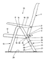
- FIG. 1 for example, an embodiment of a folding seat (10) is shown.
- This seating furniture (10) has a backrest (11), a seat part (12) articulated thereon and a pair of front legs (13) and a pair of rear legs (14).
- the side view in Fig. 1 shows only one of the pairs of legs.
- the backrest (11) is pivotally articulated on the seat part (12) via two swivel joints, only one of the swivel joints (15) being shown in FIG a recess in each tab of the backrest passes through, which is inserted into the fork-like end region (not shown).
- each front leg (13) is pivotally connected to the corresponding rear legs (14) via a swivel joint (16), the swivel joint (16) in the region of upper end sections (17) and (18) of the front or rear leg (13) or (14) is arranged.
- the front legs (13) and rear legs (14) are each articulated on the outside on the long sides (19) of the seat part (12), so that the seat part (12) lies between the pairs of legs.
- the seating furniture (10) also has a pair of armrests (20), of which only one armrest is visible due to the selected side view.
- Each of these armrests (20) is articulated via a further swivel joint (21) on the longitudinal outside of the backrest (11) and is supported in the position of use shown in FIG. 1 on the upper end sections (17) and (18) of the front legs (13 ) and hind legs (14).
- the armrests (20) can be designed as hollow profiles open at the bottom, which can be provided with a plurality of catches on the underside of the bearing surface of the armrests (20), which in turn have a pin on the top of the end sections (17) and (18 ) cooperate so that a gradual inclination adjustment of the backrest (11) is possible (not shown).
- a guide in the form of a longitudinal sliding slot (22) is incorporated into each of the rear legs (14), the sliding slots (22) being arranged on the mutually facing inner sides (23) of the rear legs (14). These sliding slots (22) run in an area on the inner sides (23) of the rear legs (14), which begins approximately in the middle section and extends into the lower third of the rear legs (14).
- the two sliding slots (22), of which only one slot can also be seen due to the side view selected in FIG. 1, are of identical design, so that in the following description only reference is made to the sliding slot (22) visible in FIG. 1 .
- Each slide slot (22) is trough-shaped with an approximately U-shaped cross section and can be formed by webs (43) projecting inwards from the inside (23), which are integrally connected to the box-shaped rear leg (14) in its longitudinal direction.
- an upper end section (24) is formed in the rear leg, which is arranged in an approximately horizontal manner but is inclined slightly (angled) downward and extends approximately into the region of a front edge (25) of the rear leg (14).
- This upper end section (24) is adjoined by an elongated straight middle section (26) which runs parallel to the longitudinal axis of the rear leg (14) or parallel to its rear edge (27) in its immediate vicinity.
- This middle section (26) in turn merges into a lower inclined end section (28) which, as shown in FIG Seating (10) is arranged essentially at a right angle to the contact surface (29) pointing downwards.
- the lower end section (28) ends in the region of the front edge (25) of the rear leg (14) (cf. FIG. 1).
- the length of a sliding slot (22) measured in a straight direction between the angled end section (24) and the lower inclined end section (28) is approximately approximately 1/3 of the total length of the rear leg (14).
- the length of a sliding slot (22) can, however, be adapted to the geometry and dimensions of the respective seating or reclining furniture and is selected so that on the one hand a stable use position and on the other hand a very space-saving storage position can be reached, in which the backrest (11 ) lies tightly on the seat part (12). This is achieved in particular by the lower end section (28) of the sliding slot (22) and its arrangement and length.
- the seat part (12) also has two outwardly projecting sliding pins (30) which are arranged below the swivel joint (15), of which in turn a sliding pin (30) is shown in FIG. 1.
- the slide pins (30) engage in the slide slots (22), the slide pin (30) being arranged in the upper angled end section (24) of the slide slot (22) in the position of the seating (10) shown in FIG. 1. Due to the horizontal or slightly downward slope of the end section (24) and the essentially inverted V-shaped arrangement of the legs of the reclining furniture (10), a force acts on the person sitting on the piece of furniture that pushes the sliding pin (30) presses into the angled end region of the end section (24) adjacent to the front edge (25).
- This elastic locking bolt (32) extends in the longitudinal direction of the sliding slot (22) and is detachably fastened in the interior of one of the two rear legs (14) designed as profile tubes on the surface side of a guide base (34) facing away from the sliding slot and has a slight arch shape in its gem.
- Fig. 7 shown side view. At the end there is a bulge (36) on the surface side of the locking bolt (32) - formed integrally with it - which removes the locking bolt (32) which extends from the open side of the guide (22) through the guide base (34) attached screw (35).
- the other upper end side of the locking bolt (32) branches into an area (37) which is angled at approximately 90 ° and to which an outer nose (38) is integrally connected at a right angle.
- the locking bolt (32) there is a groove (40) forming a receiving recess (39), the base (41) of the recess having an approximately V-shaped cross section and with the locking bolt inserted into the rear leg (14) the recess (39) itself runs transversely to the longitudinal direction of the sliding slot (22).
- the guide base (34) is provided with a rectangular recess (42) which penetrates this in the upper end section (24) and extends in the longitudinal direction of the sliding slot (22).
- the upper region of the locking bolt (32) engages between the groove (40) and the angled region (37) through this recess (42) into the sliding slot (22 ) in the area of the upper end section (24), the nose (38) the bottom (34) in the end area engages the recess (42).
- the wall of each rear leg (14) which merges into the web (43) of the sliding slot (22) (like the web (43) itself) has a slot (44, 45).
- an actuating bolt (33) of approximately U-shaped cross section can be inserted, preferably at an angle of 90 ° to the longitudinal direction of the sliding slot (22).
- the leg (46) of the actuating bolt (33) protruding into the area of the sliding slot (22) is arrow-shaped at its end. This results in bevels (47) for the sliding pin (30).
- the free end of a leg (48) of the actuating bolt (33) which can be inserted into the hollow interior of the rear leg (14) has a double V-shape. Seen from the beginning of the leg (48), it is provided with a ramp (49) due to the inward open V-shape, which presses the elastic locking bolt (32) down at its free end when inserted. This inwardly open V-shape merges into an outwardly open shape into which the cross-sectionally approximately triangular base (41) of the receiving recess (39) snaps into place when the actuating bolt (33) is moved in further.
- the locking bolt (32) is now in its locking position, so that folding the seating furniture (10) is not possible because the sliding pin (30) is fixed.
- the actuation bolt (33) is not fully inserted or stretched into the rear leg (14). Due to the open V-shape, the locking bolt (32) is pushed further out.
- the double V-shaped design of the second leg (48) of the U-shaped actuating bolt is followed by an outwardly facing V-shaped notch (51) into which the tip of the base (41), which is approximately triangular in cross section. the receiving recess (39) springs into place.
- the locking bolt (32) has left the sliding slot (22).
- the first leg is now standing (46) in the area of the sliding slot (22) up to the middle of it approximately.
- the actuating latch (33) is pulled out again and moved into the position shown in FIG. 3, this movement being caused by an interior of the actuating latch (33) at the outwardly open V-shaped end of the second leg (48) adjoining nose (50) is stopped.
- the actuating bolt is thus permanently connected to the rear leg (14) or the sliding slot (22) arranged therein.
- the folding lock (31) which is characterized by a locking bolt (32) and an operating bolt (33), can be used for seating and / or reclining furniture with a wide variety of profile sizes.
Abstract
Description
- Die Erfindung bezieht sich auf ein Sitz- und/oder Liegemöbel als Kalppmöbel mit einer Sitz- und/oder Liegefläche und mindestens einem Paar gegenüber der Sitzfläche bewegbar angeordneten Beine und vorzugsweise mit einer an der Sitzfläche verschwenkbar angelenkten Rückenlehne.
- Derartige Sitz- und/oder Liegemöbel allgemein bekannter Art zeigen den Nachteil, daß bei gewissen Handhabungen der Sessel oder die Liege unbeabsichtigt zusammenklappt, so daß Unfälle dabei auftreten können.
- Aufgabe der Erfindung ist es, ein Sitz- und/oder Liegemöbel als Klappmöbel der vorgenannten Gattung bei einfacher konstruktiver Ausbildung so zu gestalten und mit einer sichern Einrichtung zu versehen, daß das Möbel einerseits in Benutzungsstellung mittels einer Sperreinrichtung gegen unbeabsichtigtes Zusammenklappen festgelegt ist und andererseits nach ordnungsgemäßem Lösen zusammengeklappt werden kann.
- Diese Aufgabe wird bei einem Sitz- und/oder Liegemöbel der vorgenannten Gattung dadurch gelöst, daß jeweils ein in einer Längsnut eines Beinpaares verschiebbarer, an der Sitzfläche befestigter Gleitzapfen mittels eines bewegbaren Sperriegels in aufgeklappter Stellung des Möbels gehalten ist.
- Dieser Sperriegel ist in bevorzugter Weise federnd ausgebildet und einseitig an dem Bein befestigt; sein freies Ende steht im Bereich des Gleitzapfens, diesen festlegend, durch eine Ausnehmung in die Gleitbahn vor.
- Dazu ist bei einer weiteren bevorzugten Ausführungsform die Gleitbahn L-förmig ausgebildet, wobei der kurze Schenkel, der vorzugsweise abgewinkelt ist, den Gleitzapfen in Arretierstellung aufnimmt, wobei das freie Ende des Sperriegels in die Gleitbahn derart vorsteht, daß der Gleitzapfen nicht aus diesem kurzen Schenkel herausgleiten kann. Diese lösbare Sperrstellung verhindert ein unbeabsichtigtes Zusammenklappen des Möbels mit seinen bekannten nachteiligen Folgen.
- Quer zum Sperriegel, der in Längsrichtung des Beines verläuft, ist ein Betätigungsriegel verschiebbar, der das freie Ende des elastischen Sperriegels senkrecht zur Längsrichtung des Beines in Sperr- oder Klappstellung hält.
- Weitere Merkmale ergeben sich aus den Unteransprüchen.
- Der Schutz erstreckt sich nicht nur auf die Einzelmerkmale, sondern auch auf deren Kombination.
- Ein Ausführungsbeispiel der Erfindung ist in der Zeichnung dargestellt und wird im folgenden näher beschrieben. Es zeigen:
- Fig. 1 eine Seitenansicht eines Sitzmöbels in Form eines Klappstuhles;
- Fig. 2 einen Längsschnitt durch eine Klappsicherung in Sperrstellung;
- Fig. 3 einen Schnitt gemäß Linie III-III in Fig. 2;
- Fig. 4 einen Längsschnitt durch die Klappsicherung in entriegelter Stellung;
- Fig. 5 einen Schnitt gemäß Linie V-V in Fig. 4;
- Fig. 6 eine Draufsicht von Fig. 4;
- Fig. 7 eine Seitenansicht des Sperriegels;
- Fig. 8 eine Draufsicht des Sperriegels;
- Fig. 9 eine Seitenansicht des Betätigungsriegels;
- Fig. 10 eine Draufsicht des Betätigungsriegels;
- Fig. 11 einen Schnitt entsprechend dem der Fig. 3 mit einem abgewandelten Querschnitt des Beinprofilrohres, aber demselben Sperr- und Betätigungsriegel;
- Fig. 12 einen Schnitt entsprechend dem der Fig. 3, jedoch mit einem weiteren abgewandelten Querschnitt des Beinprofilrohres, aber demselben Sperr- und Betätigungsriegel.
- In Fig. 1 ist beispielsweise eine Ausführungsform eines klappbaren Sitzmöbels (10) dargestellt. Dieses Sitzmöbel (10) weist eine Rückenlehne (11), eine daran angelenkten Sitzflächenteil (12) sowie ein Paar Vorderbeine (13) und ein Paar Hinterbeine (14) auf. Die Seitenansicht in Fig. 1 zeigt hierbei lediglich eines der Beinpaare.
- Die Rückenlehne (11) ist über zwei Drehgelenke am Sitzflächenteil (12) schwenkbeweglich angelenkt, wobei in Fig. 1 lediglich eines der Drehgelenke (15) dargestellt ist, die üblicherweise aus jeweils einem Zapfen bestehen, der Ausnehmungen in einem gabelartig ausgebildeten Endbereich des Sitzflächenteiles sowie eine Ausnehmung in je einer Lasche der Rückenlehne durchgreift, die in den gabelartigen Endbereich eingeführt ist (nicht dargestellt).
- Ferner verdeutlicht Fig. 1, daß jedes Vorderbein (13) über ein Drehgelenk (16) mit den entsprechenden Hinterbeinen (14) schwenkbeweglich verbunden ist, wobei das Drehgelenk (16) im Bereich oberer Endabschnitte (17) bzw. (18) des Vorder- bzw. Hinterbeines (13) bzw. (14) angeordnet ist. Hieraus ergibt sich die aus Fig. 1 im einzelnen ersichtlich umgekehrte V-förmige Anordnung der Vorder- und Hinterbeine (13, 14), wenn sich das Sitzmöbel (10) in der in Fig. 1 gezeigten Gebrauchsstellung befindet.
- Die Vorderbeine (13) bzw. Hinterbeine (14) sind jeweils außen an den Längsseiten (19) des Sitzflächenteiles (12) angelenkt, so daß das Sitzflächenteil (12) zwischen den Beinpaaren liegt.
- Das Sitzmöbel (10) hat bei der dargestellten Ausführungsform ferner ein Paar von Armlehnen (20), von dem wiederum aufgrund der gewählten Seitenansicht nur eine Armlehne sichtbar ist. Jede dieser Armlehnen (20) ist über ein weiteres Drehgelenk (21) an der Längsaußenseite der Rückenlehne (11) angelenkt und stütz sich in der in Fig. 1 gezeigten Gebrauchsstellung auf den oberen Endabschnitten (17) bzw. (18) der Vorderbeine (13) und Hinterbeine (14) ab.
- Die Armlehnen (20) können als unten offene Hohlprofile ausgebildet sein, die mit einer Mehrzahl von Rasten an der Unterseite der Auflagefläche der Armlehnen (20) versehen sein können, die weiderum mit einem Zapfen auf der Oberseite der Endabschnitte (17) bzw. (18) zusammenwirken, so daß eine stufenweise Neigungseinstellung der Rückelehne (11) möglich ist (nicht dargestellt).
- Wie Fig. 1 ferner verdeutlicht, sind in die Hinterbeine (14) jeweils eine Führung in Form eines längsverlaufenden Gleitschlitzes (22) eingearbeitet, wobei die Gleitschlitze (22) jeweils auf den einander zugewandten Innenseiten (23) der Hinterbeine (14) angeordnet sind. Diese Gleitschlitze (22) verlaufen in einem Bereich auf den Innenseiten (23) der Hinterbeine (14), der ungefähr im mittleren Abschnitt beginnt und bis in das untere Drittel der Hinterbeine (14) reicht.
- die beiden Gleitschlitze (22), von denen aufgrund der in Fig. 1 gewählten Seitendarstellung ebenfalls nur ein Schlitz zu sehen ist, sind identisch ausgebildet, so daß bei der nachfolgenden Beschreibung lediglich auf den in Fig. 1 sichtbaren Gleitschlitz (22) Bezug genommen ist.
- Jeder Gleitschlitz (22) ist wannenförmig mit etwa U-förmigem Querschnitt ausgebildet und kann durch von der Innenseite (23) nach innen abstehende Stegen (43) ausgebildet sein, die einstückig mit dem kastenförmigen Hinterbein (14) in dessen Längsrichtung verbunden sind. Hierbei ist ein oberer Endabschnitt (24) im Hinterbein gebildet, der in etwa horizontal verzugsweise jedoch gering nach unter geneigt (abgewinkelt) angeordnet ist und etwa bis in den Bereich einer Vorderkante (25) des Hinterbeines (14) verläuft. An diesem oberen Endabschnitt (24) schließt sich ein langgestreckter gerader Mittelabschnitt (26) an, der parallel zur Längsachse des Hinterbeines (14) bzw. parallel zu seiner Hinterkante (27) in deren unmittelbarer Nachbarschaft verläuft. Dieser Mittelabschnitt (26) geht wiederum in einen unteren geneigten Endabschnitt (28) über, der, wie Fig. 1 zeigt, bei aufgestelltem Sitzmöbel (10) im wesentlichen in einem rechten Winkel zur Aufstandsfläche (29) nach unten weisend angeordnet ist. Hierbei endet der untere Endabschnitt (28) im Bereich der Vorderkante (25) des Hinterbeines (14) (vgl. Fig. 1). Die Länge eines Gleitschlitzes (22) beträgt in gerader Richtung zwischen dem abgewinkelten Endabschnitt (24) und dem unteren geneigten Endabschnitt (28) gemessen ungefähr etwa 1/3 der Gesamt länge des Hinterbeines (14). Die Länge eines Gleitschlitzes (22) kann jedoch an die Geometrie und Abmessung des jeweiligen Sitz- oder Liegemöbels angepaßt sein und ist so gewählt, daß zum einem eine standsichere Gebrauchsposition und zum anderen eine sehr platzsparende Aufbewahrungsstellung erreichbar ist, in der insbesondere die Rückenlehne (11) dicht auf dem Sitzflächenteil (12) aufliegt. Dieses wird insbesondere durch den unteren Endabschnitt (28) des Gleitschlitzes (22) und dessen Anordnung und Länge erreicht.
- Das Sitzflächenteil (12) weist ferner zwei nach außen vorstehende Gleitzapfen (30) auf, die unterhalb des Drehgelenkes (15) angeordnet sind, von denen in Fig. 1 wiederum ein Gleitzapfen (30) gezeigt ist. Die Gleitzapfen (30) greifen in die Gleitschlitze (22) ein, wobei in der in Fig. 1 dargestellten Position des Sitzmöbels (10) der Gleitzapfen (30) im oberen abgewinkelten Endabschnitt (24) des Gleitschlitzes (22) angeordnet ist. Hierbei wirkt aufgrund des horizontalen bzw. leicht nach unten geneigten Verlaufes des Endabschnittes (24) und der im wesentlichen umgekehrt V-förmigen Anordnung der Beine des Liegemöbels (10) eine Kraft von der auf dem Möbel sitzenden Person aus, die den Gleitzapfen (30) in den der Vorderkante (25) benachbarten abgewinkelten Endbereich des Endabschnittes (24) eindrückt.
- Diese konstruktive Ausbildung bietet einen gewissen guten Schutz gegen unerwünschtes Herausdrücken des Gleitzapfens (30) aus dem oberen Endabschnitt (24) und damit ein unerwünschtes Zusammenklappen des Sitzmöbels (10).
- Um jedoch selbst bei einem unerwartet herausgedrückten Gleitzapfen (30) aus dem Gleitschlitz (22) ein Zusammenklappen des Sitzmöbels (10) zu verhindern, ist in dem in den oberen Endbereich (24) übergehenden Bereich des Mittelabschnittes (26) des Gleitschlitzes (22) eine Klappsicherung (31) angeordnet, die mittels eines einen Sperriegel (32) beaufschlagenden Betätigungsriegels (33) wirksam ist.
- Dieser elastische Sperriegel (32) erstreckt sich in Längsrichtung des Gleitschlitzes (22) und ist im Inneren eines der beiden als Profilrohre ausgebildeten Hinterbeine (14) auf der von dem Gleitschlitz wegweisenden Oberflächenseite eines Führungsgrundes (34) mittels einer Schraube (35) lösbar befestigt und hat eine geringe Bogenform in seiner gem. Fig. 7 dargestellen Seitenansicht. Endseitig steht dazu eine Wulst (36) auf der Oberflächenseite des Sperriegels (32) - einstückig mit diesem ausgebildet - vor, welche die von der offenen Seite der Führung (22) her durch den Führungsgrund (34) durchgestreckte, den Sperriegel (32) lösbar befestigte Schraube (35) aufnimmt. Die andere obere Endseite des Sperrriegels (32) zweigt einen in etwa um 90 ° angewinkelten Bereich (37), an den sich rechtwinklig eine äußere Nase (38) einstückig anschließt. Im mittleren Bereich des Sperriegels (32) ist eine - eine Aufnahmeausnehmung (39) bildende - Nut (40) vorgesehen, wobei der Grund (41) der Ausnehmung einen in etwa V-förmigen Querschnitt hat und bei in das Hinterbein (14) eingesetztem Sperriegel die Ausnehmung (39) selbst quer zur Längsrichtung des Gleitschlitzes (22) verläuft.
- Der Führungsgrund (34) ist mit einer - diesen im oberen Endabschnitt (24) durchdringenden und in Längsrichtung des Gleitschlitzes (22) verlaufenden - rechteckigen Ausnehmung (42) ausgestattet. Bei im Hinterbein (14) mit dem Führungsgrund (34) lösbar befestigtem Sperriegel (32) greift der obere Bereich des Sperriegels (32) zwischen Nut (40) und dem abgewinkelten Bereich (37) durch diese Ausnehmung (42) in den Gleitschlitz (22) im Bereich des oberen Endabschnittes (24) ein, wobei die Nase (38) den Grund (34) im Endbereich der Ausnehmung (42) hintergreift. Die in den Steg (43) des Gleitschlitzes (22) übergehende Wandung jedes Hinterbeines (14) hat (wie der Steg (43) selbst) eine Schlitz (44, 45). Durch diese Schlitze (44, 45) ist jeweils ein im Querschnitt in etwa U-förmig ausgebildeter Betätigungsriegel (33) und zwar vorzugsweise in einem Winkel von 90 ° zur Längsrichtung des Gleitschlitzes (22) einsteckbar. Der in den Bereich des Gleitschlitzes (22) ragende Schenkel (46) des Betätigungsriegels (33) ist dabei an seinem Ende pfeilförmig ausgebildet. Hierdurch ergeben sich Anlaufschrägen (47) für den Gleitzapfen (30).
- Das freie Ende eines in den hohlen Innenraum des Hinterbeines (14) einsteckbaren Schenkels (48) des Betätigungsriegels (33) ist doppelt V-förmig ausgebildet. Vom Anfang des Schenkels (48) her gesehen, ist dieser durch die nach innen hin offene V-Form mit einer Auflaufschräge (49) versehen, die den elastischen Sperriegel (32) beim Einstecken an seinem freien Ende herunterdrückt. Diese nach innen hin offene V-Form geht in eine nach außen hin offene Form über, in die der im Querschnitt in etwa dreiecksförmige Grund (41) der Aufnahmeausnehmung (39) bei weiterer Einschiebebewegung des Betätigungsriegels (33) federnd einrastet. Der Sperriegel (32) befindet sich nunmehr in seiner Verriegelungsstellung, so daß ein Zusammenklappen des Sitzmöbels (10) nicht möglich ist, da der Gleitzapfen (30) festgelegt ist.
- Zur Entriegelung wird der Betätigungsriegel (33) nicht ganz in das Hinterbein (14) eingeschoben bzw. eingestreckt. Dabei wird - bedingt durch die nach außen hin offene V-Form- der Sperriegel (32) weiter nach außen gedrückt. An die doppel-V-förmige Ausbildung des zweiten Schenkels (48) des U-förmig ausgebildeten Betätigungsriegels schließt sich eine nach außen weisende V-förmige Einkerbung (51) an, in welche die Spitze des im Querschnitt in etwa dreiecksförmige ausgebildeten Grundes (41) der Aufnahmeausnehmung (39) rastend einfedert. In dieser Stellung hat der Sperriegel (32) den Gleitschlitz (22) verlassen. Es steht zwar jetzt der erste Schenkel (46) in den Bereich des Gleitschlitzes (22) bis zu dessen Mitte hin in etwa vor. Dieser ist jedoch, wie schon oben beschrieben, an seinem freien Schenkelende mit der Anlaufschräge (47) versehen, so daß bei einer Zusammenklappbewegung des Sitzmöbels (10) der Gleitzapfen (30) diesen Schenkel (46) zurückdrückt und bei weiterem Zusammenklappen dieser erste Schenkel (46) wieder in seine Ausgangslage zurückfedert.
- Soll die Klappsicherung (31) wieder in ihre Sperrstellung bzw. Verriegelungsstellung gebracht werden, so wird der Betätigungsriegel (33) wieder herausgezogen und in die in Fig. 3 dargestellte Position bewegt, wobei diese Bewegung durch eine zum Inneren des Betätigungsriegels (33), sich an des nach außen offene V-förmig ausgebildete Ende des zweiten Schenkels (48) hin anschließende Nase (50) gestoppt wird. Der Betätigungsriegel ist somit unlösbar mit dem Hinterbein (14) bzw. darin angeordneten Gleitschlitz (22) verbunden.
- Die Fig. 11 und 12 zeigen denselben erfindungsgemäßen Sperrriegel (32) mit dem ihn beaufschlagenden Betätigungsriegel (33), jedoch bei unterschiedlichen Profilen von Hinterbeinen (14) mit darauf auch unterschiedlich angeordneten Führungsbahnen. Die durch Sperriegel (32) und Betätigungsriegel (33) gekennzeichnete Klappsicherung (31) ist für Sitzund/oder Liegemöbel mit unterschiedlichsten Profilgrößen verwendbar.
Claims (11)
Applications Claiming Priority (2)
| Application Number | Priority Date | Filing Date | Title |
|---|---|---|---|
| DE3926406 | 1989-08-10 | ||
| DE3926406A DE3926406A1 (de) | 1989-08-10 | 1989-08-10 | Sitz-und/oder liegemoebel |
Publications (2)
| Publication Number | Publication Date |
|---|---|
| EP0412239A1 true EP0412239A1 (de) | 1991-02-13 |
| EP0412239B1 EP0412239B1 (de) | 1994-06-22 |
Family
ID=6386845
Family Applications (1)
| Application Number | Title | Priority Date | Filing Date |
|---|---|---|---|
| EP90103511A Expired - Lifetime EP0412239B1 (de) | 1989-08-10 | 1990-02-23 | Sitz- und/oder Liegemöbel |
Country Status (5)
| Country | Link |
|---|---|
| EP (1) | EP0412239B1 (de) |
| AT (1) | ATE107483T1 (de) |
| DE (2) | DE3926406A1 (de) |
| DK (1) | DK0412239T3 (de) |
| ES (1) | ES2058635T3 (de) |
Cited By (1)
| Publication number | Priority date | Publication date | Assignee | Title |
|---|---|---|---|---|
| EP1290962A2 (de) * | 2001-09-06 | 2003-03-12 | Borneo Tsang Furnishing SDN BHD | Automatische Verriegelung für einen mehrfach verstellbaren Stuhl |
Families Citing this family (1)
| Publication number | Priority date | Publication date | Assignee | Title |
|---|---|---|---|---|
| DE60015290T2 (de) * | 2000-02-28 | 2005-10-20 | B.T. Furnishing Sdn Bhd, Tawau | Klappstuhl |
Citations (3)
| Publication number | Priority date | Publication date | Assignee | Title |
|---|---|---|---|---|
| US2381574A (en) * | 1943-05-06 | 1945-08-07 | Abe J Jacobson | Locking device for folding chairs |
| US4162806A (en) * | 1977-12-16 | 1979-07-31 | Cho Yush Chye | Safety folding chair |
| NL8403070A (nl) * | 1984-10-09 | 1986-05-01 | Ubbink Roosendaal B V | Verstelbare en inklapbare stoel, in het bijzonder tuinstoel. |
Family Cites Families (4)
| Publication number | Priority date | Publication date | Assignee | Title |
|---|---|---|---|---|
| DE1778299U (de) * | 1958-07-14 | 1958-11-27 | Albert Spieth | Klappstuhl. |
| DE8434318U1 (de) * | 1984-11-23 | 1985-05-23 | Heinz Kettler Metallwarenfabrik Gmbh & Co, 4763 Ense | Klappsessel |
| DE3725649C1 (en) * | 1987-08-03 | 1988-09-01 | Bemico Enschede B.V., Enschede, Nl | Foldable chair with latch preventing accidental collapse - comprises key-operated transverse bolt to block legs in spread position beneath seat |
| FR2647321B1 (fr) * | 1989-05-25 | 1991-09-13 | Grosfillex Sarl | Dispositif pour incliner de facon reglable et conjuguee le dossier et l'assise d'un fauteuil |
-
1989
- 1989-08-10 DE DE3926406A patent/DE3926406A1/de not_active Withdrawn
-
1990
- 1990-02-23 EP EP90103511A patent/EP0412239B1/de not_active Expired - Lifetime
- 1990-02-23 DE DE59006190T patent/DE59006190D1/de not_active Expired - Fee Related
- 1990-02-23 DK DK90103511.3T patent/DK0412239T3/da active
- 1990-02-23 ES ES90103511T patent/ES2058635T3/es not_active Expired - Lifetime
- 1990-02-23 AT AT90103511T patent/ATE107483T1/de active
Patent Citations (3)
| Publication number | Priority date | Publication date | Assignee | Title |
|---|---|---|---|---|
| US2381574A (en) * | 1943-05-06 | 1945-08-07 | Abe J Jacobson | Locking device for folding chairs |
| US4162806A (en) * | 1977-12-16 | 1979-07-31 | Cho Yush Chye | Safety folding chair |
| NL8403070A (nl) * | 1984-10-09 | 1986-05-01 | Ubbink Roosendaal B V | Verstelbare en inklapbare stoel, in het bijzonder tuinstoel. |
Cited By (2)
| Publication number | Priority date | Publication date | Assignee | Title |
|---|---|---|---|---|
| EP1290962A2 (de) * | 2001-09-06 | 2003-03-12 | Borneo Tsang Furnishing SDN BHD | Automatische Verriegelung für einen mehrfach verstellbaren Stuhl |
| EP1290962A3 (de) * | 2001-09-06 | 2003-12-03 | Borneo Tsang Furnishing SDN BHD | Automatische Verriegelung für einen mehrfach verstellbaren Stuhl |
Also Published As
| Publication number | Publication date |
|---|---|
| ATE107483T1 (de) | 1994-07-15 |
| DK0412239T3 (da) | 1994-07-25 |
| ES2058635T3 (es) | 1994-11-01 |
| EP0412239B1 (de) | 1994-06-22 |
| DE3926406A1 (de) | 1990-09-06 |
| DE59006190D1 (de) | 1994-07-28 |
Similar Documents
| Publication | Publication Date | Title |
|---|---|---|
| DE3538833C2 (de) | ||
| DE102009048649B4 (de) | Mit einem Autositz verbindbarer Kinderwagen | |
| DE1505747C3 (de) | Längsverschiebbar gelagerter Kraftfahrzeugsitz | |
| DE2801467C2 (de) | Kleinkinder-Laufstuhl | |
| DE3312546A1 (de) | Babybett | |
| DE2506661C3 (de) | Faltstuhl | |
| EP1388309B1 (de) | Gelenk, insbesondere für Liegen | |
| DE3309174C1 (de) | Bettseitenteil | |
| DE4304597C1 (de) | Polsterträger für Fahrzeugsitze | |
| DE3113144A1 (de) | Sitzaufbau fuer kinderwaegen | |
| DE3540642A1 (de) | Sicherheitsbeschlag fuer einen zusammenfaltbaren hochstuhl | |
| EP0412239B1 (de) | Sitz- und/oder Liegemöbel | |
| DE4222276A1 (de) | Klubsessel | |
| DE2023011C3 (de) | ||
| DE2903196C2 (de) | Fahrbarer Krankenstuhl | |
| DE19931953A1 (de) | Beschlag zur Lagerung eines Endes einer Latte eines Lattenrahmens | |
| DE60015290T2 (de) | Klappstuhl | |
| DE3726451C2 (de) | ||
| DE202016100852U1 (de) | Verkettbares Gestell | |
| DE102016102465B4 (de) | Rahmen für einen Fahrradanhänger oder Kinderwagen | |
| DE2919715C2 (de) | Beinstütze | |
| DE3127310C2 (de) | ||
| DE102011108860B4 (de) | Kleinkindertransportvorrichtung und ihr Einstellverfahren | |
| EP0405392A1 (de) | Sitz -oder Liegemöbel | |
| WO1988009139A1 (en) | Head or foot adjusting jack, with several stepped engagement positions |
Legal Events
| Date | Code | Title | Description |
|---|---|---|---|
| PUAI | Public reference made under article 153(3) epc to a published international application that has entered the european phase |
Free format text: ORIGINAL CODE: 0009012 |
|
| AK | Designated contracting states |
Kind code of ref document: A1 Designated state(s): AT BE CH DE DK ES FR GB IT LI NL SE |
|
| 17P | Request for examination filed |
Effective date: 19910809 |
|
| 17Q | First examination report despatched |
Effective date: 19921217 |
|
| GRAA | (expected) grant |
Free format text: ORIGINAL CODE: 0009210 |
|
| AK | Designated contracting states |
Kind code of ref document: B1 Designated state(s): AT BE CH DE DK ES FR GB IT LI NL SE |
|
| REF | Corresponds to: |
Ref document number: 107483 Country of ref document: AT Date of ref document: 19940715 Kind code of ref document: T |
|
| REG | Reference to a national code |
Ref country code: DK Ref legal event code: T3 |
|
| GBT | Gb: translation of ep patent filed (gb section 77(6)(a)/1977) |
Effective date: 19940628 |
|
| REF | Corresponds to: |
Ref document number: 59006190 Country of ref document: DE Date of ref document: 19940728 |
|
| ITF | It: translation for a ep patent filed |
Owner name: JACOBACCI CASETTA & PERANI S.P.A. |
|
| ET | Fr: translation filed | ||
| REG | Reference to a national code |
Ref country code: ES Ref legal event code: FG2A Ref document number: 2058635 Country of ref document: ES Kind code of ref document: T3 |
|
| EAL | Se: european patent in force in sweden |
Ref document number: 90103511.3 |
|
| PG25 | Lapsed in a contracting state [announced via postgrant information from national office to epo] |
Ref country code: SE Effective date: 19950224 |
|
| PLBE | No opposition filed within time limit |
Free format text: ORIGINAL CODE: 0009261 |
|
| STAA | Information on the status of an ep patent application or granted ep patent |
Free format text: STATUS: NO OPPOSITION FILED WITHIN TIME LIMIT |
|
| 26N | No opposition filed | ||
| EUG | Se: european patent has lapsed |
Ref document number: 90103511.3 |
|
| PGFP | Annual fee paid to national office [announced via postgrant information from national office to epo] |
Ref country code: BE Payment date: 19961218 Year of fee payment: 8 |
|
| PGFP | Annual fee paid to national office [announced via postgrant information from national office to epo] |
Ref country code: AT Payment date: 19961220 Year of fee payment: 8 |
|
| PGFP | Annual fee paid to national office [announced via postgrant information from national office to epo] |
Ref country code: GB Payment date: 19970214 Year of fee payment: 8 |
|
| PGFP | Annual fee paid to national office [announced via postgrant information from national office to epo] |
Ref country code: DK Payment date: 19970217 Year of fee payment: 8 |
|
| PGFP | Annual fee paid to national office [announced via postgrant information from national office to epo] |
Ref country code: CH Payment date: 19970219 Year of fee payment: 8 |
|
| PGFP | Annual fee paid to national office [announced via postgrant information from national office to epo] |
Ref country code: NL Payment date: 19970227 Year of fee payment: 8 Ref country code: FR Payment date: 19970227 Year of fee payment: 8 Ref country code: DE Payment date: 19970227 Year of fee payment: 8 |
|
| PGFP | Annual fee paid to national office [announced via postgrant information from national office to epo] |
Ref country code: ES Payment date: 19970228 Year of fee payment: 8 |
|
| PG25 | Lapsed in a contracting state [announced via postgrant information from national office to epo] |
Ref country code: GB Free format text: LAPSE BECAUSE OF NON-PAYMENT OF DUE FEES Effective date: 19980223 Ref country code: AT Free format text: LAPSE BECAUSE OF NON-PAYMENT OF DUE FEES Effective date: 19980223 |
|
| PG25 | Lapsed in a contracting state [announced via postgrant information from national office to epo] |
Ref country code: ES Free format text: LAPSE BECAUSE OF NON-PAYMENT OF DUE FEES Effective date: 19980224 |
|
| PG25 | Lapsed in a contracting state [announced via postgrant information from national office to epo] |
Ref country code: LI Free format text: LAPSE BECAUSE OF NON-PAYMENT OF DUE FEES Effective date: 19980228 Ref country code: FR Free format text: THE PATENT HAS BEEN ANNULLED BY A DECISION OF A NATIONAL AUTHORITY Effective date: 19980228 Ref country code: CH Free format text: LAPSE BECAUSE OF NON-PAYMENT OF DUE FEES Effective date: 19980228 Ref country code: BE Free format text: LAPSE BECAUSE OF NON-PAYMENT OF DUE FEES Effective date: 19980228 |
|
| PG25 | Lapsed in a contracting state [announced via postgrant information from national office to epo] |
Ref country code: DK Free format text: LAPSE BECAUSE OF NON-PAYMENT OF DUE FEES Effective date: 19980302 |
|
| BERE | Be: lapsed |
Owner name: HEINZ KETTLER METALLWARENFABRIK G.M.B.H. & CO. K. Effective date: 19980228 |
|
| PG25 | Lapsed in a contracting state [announced via postgrant information from national office to epo] |
Ref country code: NL Free format text: LAPSE BECAUSE OF NON-PAYMENT OF DUE FEES Effective date: 19980901 |
|
| GBPC | Gb: european patent ceased through non-payment of renewal fee |
Effective date: 19980223 |
|
| REG | Reference to a national code |
Ref country code: CH Ref legal event code: PL |
|
| NLV4 | Nl: lapsed or anulled due to non-payment of the annual fee |
Effective date: 19980901 |
|
| PG25 | Lapsed in a contracting state [announced via postgrant information from national office to epo] |
Ref country code: DE Free format text: LAPSE BECAUSE OF NON-PAYMENT OF DUE FEES Effective date: 19981103 |
|
| REG | Reference to a national code |
Ref country code: FR Ref legal event code: ST |
|
| REG | Reference to a national code |
Ref country code: DK Ref legal event code: EBP |
|
| REG | Reference to a national code |
Ref country code: ES Ref legal event code: FD2A Effective date: 20000503 |
|
| PG25 | Lapsed in a contracting state [announced via postgrant information from national office to epo] |
Ref country code: IT Free format text: LAPSE BECAUSE OF NON-PAYMENT OF DUE FEES Effective date: 20050223 |