EP0412217A1 - Procédé et dispositif pour la fabrication d'articles allongés - Google Patents
Procédé et dispositif pour la fabrication d'articles allongés Download PDFInfo
- Publication number
- EP0412217A1 EP0412217A1 EP89308085A EP89308085A EP0412217A1 EP 0412217 A1 EP0412217 A1 EP 0412217A1 EP 89308085 A EP89308085 A EP 89308085A EP 89308085 A EP89308085 A EP 89308085A EP 0412217 A1 EP0412217 A1 EP 0412217A1
- Authority
- EP
- European Patent Office
- Prior art keywords
- orifice
- cross
- synthetic resin
- additional
- continuous
- Prior art date
- Legal status (The legal status is an assumption and is not a legal conclusion. Google has not performed a legal analysis and makes no representation as to the accuracy of the status listed.)
- Granted
Links
- 238000004519 manufacturing process Methods 0.000 title claims abstract description 40
- 239000000463 material Substances 0.000 claims abstract description 88
- 229920003002 synthetic resin Polymers 0.000 claims abstract description 61
- 239000000057 synthetic resin Substances 0.000 claims abstract description 61
- 238000000034 method Methods 0.000 claims abstract description 27
- 238000001125 extrusion Methods 0.000 claims description 26
- 230000015572 biosynthetic process Effects 0.000 claims description 11
- 238000000465 moulding Methods 0.000 abstract description 33
- 229920005989 resin Polymers 0.000 description 18
- 239000011347 resin Substances 0.000 description 18
- 238000009966 trimming Methods 0.000 description 15
- 238000005520 cutting process Methods 0.000 description 4
- 239000002184 metal Substances 0.000 description 4
- 238000010586 diagram Methods 0.000 description 3
- 230000000694 effects Effects 0.000 description 3
- XLYOFNOQVPJJNP-UHFFFAOYSA-N water Substances O XLYOFNOQVPJJNP-UHFFFAOYSA-N 0.000 description 3
- KRHYYFGTRYWZRS-UHFFFAOYSA-M Fluoride anion Chemical compound [F-] KRHYYFGTRYWZRS-UHFFFAOYSA-M 0.000 description 2
- 238000001816 cooling Methods 0.000 description 2
- 230000005484 gravity Effects 0.000 description 2
- 239000008188 pellet Substances 0.000 description 2
- NLHHRLWOUZZQLW-UHFFFAOYSA-N Acrylonitrile Chemical compound C=CC#N NLHHRLWOUZZQLW-UHFFFAOYSA-N 0.000 description 1
- 229920000122 acrylonitrile butadiene styrene Polymers 0.000 description 1
- 239000000470 constituent Substances 0.000 description 1
- 238000007599 discharging Methods 0.000 description 1
- 230000001747 exhibiting effect Effects 0.000 description 1
- 238000010438 heat treatment Methods 0.000 description 1
- 239000002440 industrial waste Substances 0.000 description 1
- 229920000554 ionomer Polymers 0.000 description 1
- 239000007769 metal material Substances 0.000 description 1
- 238000001465 metallisation Methods 0.000 description 1
- 238000012986 modification Methods 0.000 description 1
- 230000004048 modification Effects 0.000 description 1
- 230000002093 peripheral effect Effects 0.000 description 1
- 239000000049 pigment Substances 0.000 description 1
- 229920003229 poly(methyl methacrylate) Polymers 0.000 description 1
- 229920000915 polyvinyl chloride Polymers 0.000 description 1
- 239000004800 polyvinyl chloride Substances 0.000 description 1
- 238000007711 solidification Methods 0.000 description 1
- 230000008023 solidification Effects 0.000 description 1
Images


Classifications
-
- B—PERFORMING OPERATIONS; TRANSPORTING
- B60—VEHICLES IN GENERAL
- B60J—WINDOWS, WINDSCREENS, NON-FIXED ROOFS, DOORS, OR SIMILAR DEVICES FOR VEHICLES; REMOVABLE EXTERNAL PROTECTIVE COVERINGS SPECIALLY ADAPTED FOR VEHICLES
- B60J1/00—Windows; Windscreens; Accessories therefor
- B60J1/20—Accessories, e.g. wind deflectors, blinds
- B60J1/2002—Wind deflectors specially adapted for preventing soiling, e.g. for side windows
-
- B—PERFORMING OPERATIONS; TRANSPORTING
- B29—WORKING OF PLASTICS; WORKING OF SUBSTANCES IN A PLASTIC STATE IN GENERAL
- B29C—SHAPING OR JOINING OF PLASTICS; SHAPING OF MATERIAL IN A PLASTIC STATE, NOT OTHERWISE PROVIDED FOR; AFTER-TREATMENT OF THE SHAPED PRODUCTS, e.g. REPAIRING
- B29C48/00—Extrusion moulding, i.e. expressing the moulding material through a die or nozzle which imparts the desired form; Apparatus therefor
- B29C48/001—Combinations of extrusion moulding with other shaping operations
- B29C48/0022—Combinations of extrusion moulding with other shaping operations combined with cutting
-
- B—PERFORMING OPERATIONS; TRANSPORTING
- B29—WORKING OF PLASTICS; WORKING OF SUBSTANCES IN A PLASTIC STATE IN GENERAL
- B29C—SHAPING OR JOINING OF PLASTICS; SHAPING OF MATERIAL IN A PLASTIC STATE, NOT OTHERWISE PROVIDED FOR; AFTER-TREATMENT OF THE SHAPED PRODUCTS, e.g. REPAIRING
- B29C48/00—Extrusion moulding, i.e. expressing the moulding material through a die or nozzle which imparts the desired form; Apparatus therefor
- B29C48/03—Extrusion moulding, i.e. expressing the moulding material through a die or nozzle which imparts the desired form; Apparatus therefor characterised by the shape of the extruded material at extrusion
- B29C48/07—Flat, e.g. panels
-
- B—PERFORMING OPERATIONS; TRANSPORTING
- B29—WORKING OF PLASTICS; WORKING OF SUBSTANCES IN A PLASTIC STATE IN GENERAL
- B29C—SHAPING OR JOINING OF PLASTICS; SHAPING OF MATERIAL IN A PLASTIC STATE, NOT OTHERWISE PROVIDED FOR; AFTER-TREATMENT OF THE SHAPED PRODUCTS, e.g. REPAIRING
- B29C48/00—Extrusion moulding, i.e. expressing the moulding material through a die or nozzle which imparts the desired form; Apparatus therefor
- B29C48/03—Extrusion moulding, i.e. expressing the moulding material through a die or nozzle which imparts the desired form; Apparatus therefor characterised by the shape of the extruded material at extrusion
- B29C48/12—Articles with an irregular circumference when viewed in cross-section, e.g. window profiles
-
- B—PERFORMING OPERATIONS; TRANSPORTING
- B29—WORKING OF PLASTICS; WORKING OF SUBSTANCES IN A PLASTIC STATE IN GENERAL
- B29C—SHAPING OR JOINING OF PLASTICS; SHAPING OF MATERIAL IN A PLASTIC STATE, NOT OTHERWISE PROVIDED FOR; AFTER-TREATMENT OF THE SHAPED PRODUCTS, e.g. REPAIRING
- B29C48/00—Extrusion moulding, i.e. expressing the moulding material through a die or nozzle which imparts the desired form; Apparatus therefor
- B29C48/16—Articles comprising two or more components, e.g. co-extruded layers
- B29C48/18—Articles comprising two or more components, e.g. co-extruded layers the components being layers
- B29C48/21—Articles comprising two or more components, e.g. co-extruded layers the components being layers the layers being joined at their surfaces
-
- B—PERFORMING OPERATIONS; TRANSPORTING
- B29—WORKING OF PLASTICS; WORKING OF SUBSTANCES IN A PLASTIC STATE IN GENERAL
- B29C—SHAPING OR JOINING OF PLASTICS; SHAPING OF MATERIAL IN A PLASTIC STATE, NOT OTHERWISE PROVIDED FOR; AFTER-TREATMENT OF THE SHAPED PRODUCTS, e.g. REPAIRING
- B29C48/00—Extrusion moulding, i.e. expressing the moulding material through a die or nozzle which imparts the desired form; Apparatus therefor
- B29C48/25—Component parts, details or accessories; Auxiliary operations
- B29C48/36—Means for plasticising or homogenising the moulding material or forcing it through the nozzle or die
- B29C48/50—Details of extruders
- B29C48/695—Flow dividers, e.g. breaker plates
- B29C48/70—Flow dividers, e.g. breaker plates comprising means for dividing, distributing and recombining melt flows
-
- B—PERFORMING OPERATIONS; TRANSPORTING
- B60—VEHICLES IN GENERAL
- B60J—WINDOWS, WINDSCREENS, NON-FIXED ROOFS, DOORS, OR SIMILAR DEVICES FOR VEHICLES; REMOVABLE EXTERNAL PROTECTIVE COVERINGS SPECIALLY ADAPTED FOR VEHICLES
- B60J10/00—Sealing arrangements
- B60J10/20—Sealing arrangements characterised by the shape
- B60J10/22—Sealing arrangements characterised by the shape having varying cross-section in the longitudinal direction
-
- B—PERFORMING OPERATIONS; TRANSPORTING
- B60—VEHICLES IN GENERAL
- B60J—WINDOWS, WINDSCREENS, NON-FIXED ROOFS, DOORS, OR SIMILAR DEVICES FOR VEHICLES; REMOVABLE EXTERNAL PROTECTIVE COVERINGS SPECIALLY ADAPTED FOR VEHICLES
- B60J10/00—Sealing arrangements
- B60J10/20—Sealing arrangements characterised by the shape
- B60J10/26—Sealing arrangements characterised by the shape characterised by the surface shape
- B60J10/265—Sealing arrangements characterised by the shape characterised by the surface shape the surface being primarily decorative
-
- B—PERFORMING OPERATIONS; TRANSPORTING
- B60—VEHICLES IN GENERAL
- B60J—WINDOWS, WINDSCREENS, NON-FIXED ROOFS, DOORS, OR SIMILAR DEVICES FOR VEHICLES; REMOVABLE EXTERNAL PROTECTIVE COVERINGS SPECIALLY ADAPTED FOR VEHICLES
- B60J10/00—Sealing arrangements
- B60J10/30—Sealing arrangements characterised by the fastening means
-
- B—PERFORMING OPERATIONS; TRANSPORTING
- B60—VEHICLES IN GENERAL
- B60J—WINDOWS, WINDSCREENS, NON-FIXED ROOFS, DOORS, OR SIMILAR DEVICES FOR VEHICLES; REMOVABLE EXTERNAL PROTECTIVE COVERINGS SPECIALLY ADAPTED FOR VEHICLES
- B60J10/00—Sealing arrangements
- B60J10/70—Sealing arrangements specially adapted for windows or windscreens
-
- B—PERFORMING OPERATIONS; TRANSPORTING
- B29—WORKING OF PLASTICS; WORKING OF SUBSTANCES IN A PLASTIC STATE IN GENERAL
- B29C—SHAPING OR JOINING OF PLASTICS; SHAPING OF MATERIAL IN A PLASTIC STATE, NOT OTHERWISE PROVIDED FOR; AFTER-TREATMENT OF THE SHAPED PRODUCTS, e.g. REPAIRING
- B29C2793/00—Shaping techniques involving a cutting or machining operation
- B29C2793/0063—Cutting longitudinally
Definitions
- the present invention relates to a method of, and an apparatus for manufacturing a plurality of kinds of elongate articles, e.g. moldings for automobiles and the like, or segments of such moldings.
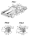
- a variety of moldings are used widely, such as front or rear window moldings, body side moldings, etc., for automobiles, which are generally composed of extruded synthetic resin material.
- Japanese Patent Application Laid-open Publication No. 61-135,824 discloses a windshield molding member which includes an upper segment to extend along an upper edge of a windshield plate, a pair of side segments to extend along side edges of the windshield plate, and a pair of corner segments connecting the upper and side segments into an integral component.
- the upper and side segments are composed of synthetic resin material extruded into respectively predetermined cross-sections which are basically similar but slightly different from each other. More particularly, the upper segment includes a main body which is provided with a first lip section to be engaged with the other surface of a windshield plate, a second lip section to be engaged with the outer surface of vehicle body panel, and a leg section to be inserted into a gap between the edge of the windshield plate and the body panel.
- the leg section has fins on both sides to be engaged with the periphery of the windshield plate and the body panel, respectively, so as to prevent undesirable withdrawal of the lip section out of the gap.
- the upper segment may have an ornamental film and a core element arranged in the main body and the leg section, respectively, depending upon ornamental and/or functional requirements.
- the side segment has a basic cross-section which is the same as that of the upper segment, as well as an additional section in the form of a ridge on the first lip section, which is adapted to define a weir or channel extending along a side edge of the windshield plate.
- the upper segment without ridge serves to realize a flush surface of the automobile body along the upper edge of the windshield plate, while the ridge on the side segment achieves the functions to guide rain water on the windshield plate to flow along the weir or channel, and to thereby prevent the rain water from flowing onto side windows across the side segment and neighboring body panel portion (or pillar) to disturb the driver's sight through the side windows.
- the die plate may have a single orifice or, as disclosed in e.g. Japanese patent Application Laid-open Publication Nos. 54-93,055; 57-185,133; 58-205,746; 59-59,426 and 60-116,423 the resin material may be extruded from a plurality of orifices closely arranged in a single die plate, and the extrusions subsequently adhered to each other.
- this process is for the manufacture of elongate articles with a single kind of cross-section only; in order to manufacture molding members or segments with mutually different cross-sections, it is necessary to prepare a plurality of exchangeable die plates.
- the exchange of the die plates requires troublesome and time-consuming manual operations, and also it is necessary to carry out a test-running extrusion after each exchange of the die plate, in order to confirm that the synthetic resin material can be stably extruded into a continuous body with a desired accuracy of the cross-section.
- the synthetic resin material as well as the ornamental film and the core element which have been extruded from the die plate during the test-running extrusion period, have to be disposed of as industrial waste materials.
- Alternate use of different die plates to produce different elongate articles of basically the same cross-section proved to be disadvantageous in many cases, particularly when a relatively small number of elongate articles of various cross-sections are to be produced in each production lot.
- a method of manufacturing a plurality of kinds of elongate articles having a cross-sectional portion which is common to all the kinds of the elongate articles to be manufactured, at least one kind of said elongate articles further having at least one additional cross-sectional portion said method characterised by the steps of: using a single extrusion die head including a die plate formed with a first orifice having a cross-section corresponding to that of said common cross-sectional portion of an elongate article, and also with at least one additional orifice having a cross-section corresponding to that of said additional cross-sectional portion of said at least one kind of elongate articles; extruding from said first orifice of said die plate a molten synthetic resin material to form a first continuous body corresponding to first elongate articles; and extruding from said first orifice and at least one additional orifice of said die plate synthetic resin materials in their molten states, and causing the extrude
- an apparatus for manufacturing a plurality of kinds of elongate articles having a cross-sectional portion which is common to all the kinds of the elongate articles to be manufactured, at least one kind of said elongate articles further having at least one additional cross-section portion said apparatus comprising: an extrusion die head including a die plate formed with a first orifice having a cross-section corresponding to that of said common cross-sectional portion of an elongate article, and also with at least one additional orifice having a cross-section corresponding to that of said additional cross-sectional portion of said at least one kind of elongate articles; and means for selecting and controlling first and second operational modes of the apparatus such that, in said first operational mode of the apparatus, synthetic resin material is extruded from said first orifice of said die plate to form a first continuous body corresponding to first elongate articles and, in said second operational mode of the apparatus, synthetic resin materials are extruded from said first orifice and at least
- the orifices in the die plate may be arranged close to each other.
- the present invention makes use of a single extrusion die head including a die plate formed with a first orifice and at least one additional orifice which are arranged close to each other.
- a first continuous body corresponding e.g. to the upper segments of a windshield molding member can be manufactured either by extruding molten synthetic resin material from the first orifice alone, or by extruding resin materials from both the first orifice and the additional orifice while preventing adhesion of the resin material from the first orifice with the resin material from the first orifice. In the latter case, the resin material from the additional orifice can be recovered and used again.
- a second continuous body corresponding e.g. to the side segments of the molding member can be manufactured by extruding resin materials from both the first orifice and the additional orifice and causing the extruded material to adhere with each other while they are still hot and in molten states.
- the present invention it is possible to manufacture a plurality of kinds of elongate articles with basically same and slightly different cross-sections, by using a single extrusion die plate with a first orifice and at least one additional orifice.
- the present invention thus allows a plurality of kinds of elongate articles to be manufactured continuously and economically, without requiring exchange of the die plate as well as a test-running extrusion after each exchange of the die plate.
- the invention allows different elongate articles of basically the same cross-section to be more readily and reliably manufactured in a continuous manner and with a higher productivity.
- the windshield molding member 5 includes an upper segment 7 to extend along an upper edge of the windshield plate 2, a pair of side segments 8 to extend along the side edges of the windshield plate 2, and a pair of corner segments 9 connecting the upper and side segments 7, 8 into an integral component.
- the upper and side segments 7, 8 are composed of appropriate synthetic resin material, such as ABS resin, acrylonitrile resin, polyvinylchloride resin, methylmethacrylate resin, ionomer resin, etc., extruded into respectively predetermined cross-sections which are basically same and slightly different from each other.
- appropriate synthetic resin material such as ABS resin, acrylonitrile resin, polyvinylchloride resin, methylmethacrylate resin, ionomer resin, etc.
- the upper segment 7 includes a main body 7a which is provided with a first lip section 7b to be engaged with the outer surface of a windshield plate 2, a second lip section 7c to be engaged with the outer surface of the vehicle body panel 10, and a leg section 7d to be inserted into a gap 11 between the edge of the windshield plate 2 and the body panel 10.
- the leg section has fins 7e, 7f on its both sides to be engaged with the periphery of the windshield plate 2 and the body panel 11, respectively, so as to prevent undesirable withdrawal of the leg section 7d out of the gap 10.
- the upper segment 7 has an ornamental film 12 and a core element 13 arranged in the main body 7a and the leg section 5d, respectively.
- the cross-section of the upper segment 7 is common to the side segments 8, and will thus be referred to as "common cross-section".
- the side segment 8 has a basic cross-sectional portion 14 with the above-mentioned common cross-section of the upper segment 7, as well as an "additional cross-sectional portion" in the form of a ridge 15 on the first lip section 7b.
- the ridge 15 defines a channel or weir 16 extending along a side edge of the windshield plate 2, whereby rain water on the windshield plate 2 can be guided along the ridge 15 and prevented from flowing onto the side windows 4 across the side segment 8 and the neighboring pillar of the vehicle body 1 to disturb the driver's sight through the side windows 4.
- the corner segment 9 for connecting the upper and side segments 7, 8 into an integral component is shown in Fig. 4, and may be composed of an appropriate synthetic resin material or metal sheet material.
- the corner segment 9 has an outer portion with a cross-section which gradually changes from that of the upper segment 7 to that of the side segment 8.
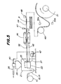
- Fig. 5 shows the schematic diagram of a production line which can be to carry out the method according to the present invention for continuously manufacturing the upper and side segments 7, 8 mentioned above.
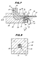
- the production line includes, as shown in Figs. 6 and 7, an extruder 21 with an extrusion die head 22 comprising an adapter 23 and a die plate 24 fixedly secured thereto.
- the extruder 21 is connected with a material supply pipe 25 and a hopper 26 for a synthetic resin material in the form of pellets.
- the extruder 21 serves to heat the resin material above its softening temperature, which is then fed to the die head 22 in a molten state.
- the extruder 21 has a passage 27 for discharging the resin material, which is connected to a pair of passages 28, 29 formed in the adaptor 23.
- the die plate 24 has a pair of orifices 30, 31 (Fig. 8) which are connected to the passages 28, 29, respectively, and arranged spaced from, but close to each other.
- the orifice 30 in the die plate 24 has a cross-sectional contour corresponding to that of the basic, common cross-sectional portion 14 of the upper and side molding segments 7, 8, and will be referred to as "common orifice”.
- the orifice 31, in turn, has a cross-sectional contour corresponding to that of the additional cross-sectional portion or ridge 15 of the side molding segments 8, and will be referred to as "additional orifice".
- the die head 22 is provided, on the discharge side of the die plate 24, with a stationary guide member 32 and a movable guide member 33 which is arranged opposite to and below the stationary guide member 32.
- the movable guide member is connected to an actuator, such as a hydraulic or pneumatic cylinder device 34, and can be moved toward and away from the stationary guide member 32.
- the stationary guide member 32 serves to guide the upper surface of the synthetic resin material 35 which has been extruded from the common orifice 30.
- the movable guide member 33 in turn, has a groove 36 with a smooth surface which serves to guide the synthetic resin material 37 extruded from the additional orifice 31.
- the movable guide member 33 as a whole, or at least the region of its groove 36, is composed of a metal material or a hard resin material which does not exhibit the tendency of adhesion with the extruded synthetic resin material 37.
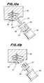
- the movable guide member 33 on its upper surface is provided with a frame 38 adjacent to the die plate 24, which supports a cutter blade 39 in the form of a metal wire, as particularly shown in Figs. 9a, 10a and 11.
- the synthetic resin material from the supply pipe 25 and the hopper 26 is heated by the extruder 21 above the softening temperature, and is fed to the die head 22 in a molten state, as shown at 40.
- the die head 22 is further fed with an ornamental film 12 and cores 13 from respective uncoilers 41, which are passed through predetermined locations of the orifice 30 for the common cross-sectional portion 14 of the segments 7, 8.
- the ornamental film 12 and the cores 13 are illustrated in Fig. 5 by a single solid line.
- the die plate 24 extrudes the synthetic resin materials 35, 37 for the common cross-sectional portion 14 and the additional cross-sectional portion 15 from the orifices 30, 31 in the die plate 24, respectively. Due to the independently of the orifices 30, 31, the synthetic resin materials 35, 37 as extruded are spaced from each other.
- the movable guide member 33 is maintained in its retracted position shown in Fig. 7, during the initial test-running period of extrusion, so that the two extruded synthetic resin materials 35, 37 are kept spaced from each other.
- the synthetic resin material 37 for the additional cross-sectional portion 15 advances downwardly by the gravity, as soon as it leaves the guide member 33, without being adhered to the synthetic resin material 35 for the common cross-sectional portion 14, and is collected by a collector 42 and returned, as reusable pellets, to the hopper 26 via a return pipe 43.
- a first step is carried out to initially manufacture the side segments 8 which include both the common cross-sectional portion 14 and the additional cross-sectional portion 15.
- the actuator 34 is put into operation to move the movable guide member 33 toward the stationary guide member 32.
- the cutter blade 39 supported by the frame 38 on the movable guide member 33 is advanced into and across the synthetic resin materials 37 for the additional cross-sectional portion 15, which has already been extruded from the additional orifice 31, to cut it away.
- a newly extruded synthetic resin material 37 is guided along the groove 36 in the movable guide member 33 and urged against the synthetic resin material 35 for the common cross-sectional portion 14 which, in turn, has been extruded from the common orifice 30 and guided and supported from its upper side by the stationary guide member 32.
- the extruded two synthetic resin materials 35, 37 are caused to immediately adhere with each other while they are still hot and in molten states, to form a continuous body 44 with a cross-section which corresponds to that of the side segment 8.
- the continuous body 44 in which the extruded synthetic resin materials 35, 37 are in adhesion with each other, is subjected to cooling and solidification in a cooling tank 45, hauled by a hauling device 46 and cut by a cutting device 47 into a predetermined length of a molding member side segment 8 while detecting the extruded length of the continuous body 44 by a sensor 48.
- the continuous body 44 may be passed through an idler roller 49 and position sensors 50a, 50b for detecting the supplied length and/or position of the continuous body 44 and may then be wound onto a drum 51, when it is desired to effect cutting of the continuous body 44 into side segments 8 at a later stage.
- a second step is carried out to manufacture the upper segments 7 which include only the common cross-sectional portion 14.
- the actuator 34 is retracted to move the movable guide member 33 away from the stationary guide member 32.
- the cutter blade 39 on the movable guide member 33 is moved across the synthetic resin material 37, which has already been extruded from the additional orifice 31, to cut it away.
- Fig. 7 and Figs. 10a and 10b the actuator 34 is retracted to move the movable guide member 33 away from the stationary guide member 32.
- the cutter blade 39 on the movable guide member 33 is moved across the synthetic resin material 37, which has already been extruded from the additional orifice 31, to cut it away.
- a newly extruded synthetic resin material 37 is guided along the groove 36 in the guide member 33, kept spaced from the synthetic resin material 35 for the common cross-sectional portion 14, and is received by the collector 42 after a downward movement by the gravity.
- the synthetic resin material 35 extruded from the common orifice 30 forms a continuous body 52 with the common cross-section which, like the continuous body 44, is transferred to successive work stations and cut into a predetermined length of the upper segment 7.
- the initial test-running extrusion was carried out with respect to the continuous body 52 corresponding to the upper segments 7 with the common cross-sectional portion 14 only.
- the test-running extrusion may be carried out with respect to the continuous body 44 which corresponds to the side segments 8 with the common cross-sectional portion 14 and the additional cross-sectional portion 15.
- the upper segments 7 and side segments 8 may be produced in the first and second steps, respectively, instead of producing the side segments 8 in the first step and the upper segments 7 in the second step as in the above-mentioned example.
- Fig. 13 shows another embodiment of the movable guide member 33 which is arranged adjacent to the extrusion die plate 24, and in opposition to the stationary guide member 32, for guiding the synthetic resin material 37 corresponding to the additional cross-sectional portion 15 of the side segment 8.
- the guide member 33 of this embodiment includes a frame 53 connected to the actuator 34, which supports a pair of rotatable guide rollers 54, 55 and a cutting blade 56 in the form of a metal wire.
- the guide rollers 54, 55 are provided, on their respective outer peripheral surfaces, with circumferential guide grooves 57, 58 and jointly serve to guide the extruded synthetic resin material 37 in their common tangential direction.
- the upper segment 7 is composed of a profiled main body 7a prepared by subjecting a metal strip to a roll forming operation, as well as a lip section 7b of an extruded synthetic resin material, which is to be brought into contact with the outer surface of a windshield plate 2, and which forms the common cross-sectional portion 14.
- a clip 17 is secured to the main body 7a, and is adapted to be engaged with a retainer 18 on the vehicle body panel 10 to retain the segment 7 in place.
- the side segment 8 also includes the common cross-sectional portion 14, and differs from the upper segment 7 in that it is provided with an additional cross-sectional portion 15 in the form of a ridge on the lip section 7b.
- the method according to the present invention can also be applied to manufacture automobile side molding members 6 as shown in Figs. 16 and 17.
- the side molding member 6 in Fig. 16 includes a main body 6a with a core strip 13 embedded therein, forming a common cross-sectional portion 14.
- the side molding member 6 in Fig. 17 includes, beside the common cross-sectional portion 14, an additional cross-sectional portion 15 formed of a plurality of longitudinally extending ornamental ridges.
- the two kinds of the side molding members 6 can be selectively used, for example according to the user's option or to the grade of the automobile.
- the common cross-sectional portion and the additional cross-sectional portion may be desirable to form with mutually different color, transparency and/or hardness.
- the ridge 15 of the side segments may be desirable for the ridge 15 of the side segments to have a hardness which is higher than that of the main body 7a in order to prevent deformation of the ridge 15.
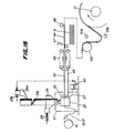
- Fig. 18 shows another embodiment of the production line which is substantially similar to that shown in Fig. 5, but which differs therefrom in that two extruder 21, 21a are associated with the extrusion die head 22.
- the production line of this embodiment can be used to manufacture upper and side segments 7, 8 of a windshield molding member 5, by extruding one or more kinds of synthetic resin materials into continuous bodies 44, 52 corresponding, respectively, to the common cross-sectional portion 14 and the additional cross-sectional portion 15 which are different in color, transparency and/or hardness from each other.
- the first extruder 21 is connected with the common orifice 30 in the die plate 24 through a passage 28, while the second extruder 21a is connected with the additional orifice 31 through a passage 29.
- the second extruder 21a has a hopper 26a which is connected to the collector 42 through the return pipe 46, and which is supplied with a synthetic resin material from its material supply pipe 25a.
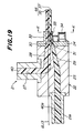
- the side segments 8 and upper segments 7 of a windshield molding member 5 can be manufactured in first and second steps, respectively, substantially in the manner described above with reference to Fig. 5.
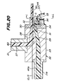
- the first step is shown in Fig. 19, and the second step is shown in Fig. 20.
- the first extruder 21, which serves to extrude the synthetic resin material 35 into the common cross-sectional portion 14, is maintained operative during the first and second steps.
- the second extruder 21a may be maintained inoperative during the second step, or during the formation of the upper segments 7 which correspond to the continuous body 52 without the additional cross-sectional portion 15.
- the additional orifice 31 in the die plate 24 need not be arranged below the common orifice 30; it may thus be arranged above or on one side of the common orifice 30.
- the second extruder 21a may be maintained operative during the second step.
- the production line shown in Fig. 18 features the provision of two extruders 21, 21a.
- the synthetic resin material to be supplied to the first extruder 21 may thus be different from the synthetic resin material to be supplied to the second extruder 21a, to realize the common cross-sectional portion 14 and the additional cross-sectional portion 15 which are different from each other in color, transparency and/or hardness.
- the two kinds of the synthetic resin materials should have an excellent cross-solubility or compatability.
- the common cross-sectional portion 14 and the additional cross-sectional portion 15 with mutually different color, transparency and/or hardness can be realized even when using a single kind of synthetic resin material, by an addition of different pigments to the synthetic resin material, and/or by an appropriate adjustment of the heating temperature or the like process conditions.
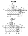
- the production lines shown in Figs. 5 and 18 may be modified so that it can be used to manufacture more than two kinds of cross-sections of the molding members or segments therefor. More particularly, as shown in Figs 21 to 26, the common cross-sectional portion 14 may have an ornamental film 12 which is completely embedded in the main body 7a and which can be optionally exposed outside by removing part of the surface material 12a of the main body 7a. By selectively removing the surface material 12a of the main body 7a in the upper and side segments 7, 8, it is possible to efficiently and economically manufacture four kinds of basically same and slightly different cross-sections with only one die plate. To this end, a trimming device 60 may be arranged adjacent to the die plate 24 and also to the movable guide member 33.
- the trimming device 60 includes a pair of rotatable trimming blades 61, and an actuator 62 which is adapted to move the trimming blades 61 toward and away from the continuous body 35 corresponding to the common cross-sectional portion 14.
- the actuator 62 may be composed of a hydraulic or pneumatic cylinder device with a piston rod which is connected to the common rotational shaft of the trimming blades 61.
- the method according to the present invention may be carried out in the following four steps.
- the continuous bodies 35, 37 corresponding to the common cross-sectional portion 14 and the additional cross-sectional portion 15 extruded from the die plate 24 are caused to adhere with each other substantially in the manner described with reference to the previous embodiments, to manufacture side segments 8 of a windshield molding member 5.
- the continuous body 35 as extruded has an ornamental film 12 completely embedded in the main body 7a.
- the ornamental film 12 is preferably composed of a transparent fluoride resin film layer with a poor tendency of adhesion to the surface material 12a to be removed, or an excellent separability from the surface material 12a, a suitably colored resin sheet or a metal deposition layer for the ornamental purpose, and a resin sheet with an excellent compatability with the synthetic resin material of the main body 7a, which are laminated with each other in the stated sequence from the outer surface side.
- the trimming blades 61 are maintained in the operative position in contact with the above-mentioned fluoride resin film to effect trimming of the surface material 12a of the main body 5a and expose the ornamental film 12.
- side segments 8 are manufactured with the surface material 12a of the main body removed and the ornamental film 12 exposed.
- the actuator 62 of the trimming device 60 is operated to retract its piston rod and disengage the trimming blades 61 from the continuous body 35 to stop the trimming of the surface material 12a of the main body 7a.
- side segments 8 are manufactured with the surface material 12a of the main body covering the ornamental film 12.
- the actuator 34 of the movable guide member 33 is operated to move the guide member 33 away from the stationary guide member 32.
- upper segments 7 are formed in the manner described with reference to the previous embodiments.
- the trimming blades 61 are maintained in the operative position to effect trimming of the surface material 12a of the main body 5a and expose the ornamental film 12.
- upper segments 8 are manufactured with the surface material 12a of the main body removed and the ornamental film 12 exposed.
- the actuator 62 of the trimming device 60 is operated to retract its piston rod and disengage the trimming blades 61 from the continuous body 35 to stop the trimming of the surface material of the main body 7a.
- upper segments 8 are manufactured with the surface material 12a of the main body covering the ornamental film 12.
- the supply of the ornamental film 12 is not necessary during the second and fourth steps, and the ornamental film 12 may be replaced by a less expensive core resin film which is the same in configuration as that of the ornamental film 12, and which is composed of a material exhibiting an excellent compatibility with the synthetic resin material of the main body 7a.
- Use of such a core resin film during the second and fourth steps serves to substantially reduce the production cost and, at the same time, to preserve a required shape stability of the continuous body 35.
- the present invention it is possible to manufacture a plurality of kinds of elongate articles with basically same and slightly different cross-sections, by using a single extrusion die plate with a common orifice and at least one additional orifice.
- the present invention allows a plurality of kinds of elongate articles to be manufactured continuously and economically, without requiring exchange of the die plates as well as a resultant test-running extrusion after each exchange of the die plate.
- the die plate may be formed with two or more additional orifices each associated with a movable guide member.
Priority Applications (1)
| Application Number | Priority Date | Filing Date | Title |
|---|---|---|---|
| DE68918858T DE68918858T2 (de) | 1989-08-09 | 1989-08-09 | Verfahren und Vorrichtung zur Herstellung von länglichen Gegenständen. |
Applications Claiming Priority (2)
| Application Number | Priority Date | Filing Date | Title |
|---|---|---|---|
| US07/390,413 US5112547A (en) | 1989-08-07 | 1989-08-07 | Method of making an elongate article |
| CA000607867A CA1330695C (fr) | 1989-08-07 | 1989-08-09 | Appareil servant a la fabrication d'articles allonges et methode connexe |
Publications (2)
| Publication Number | Publication Date |
|---|---|
| EP0412217A1 true EP0412217A1 (fr) | 1991-02-13 |
| EP0412217B1 EP0412217B1 (fr) | 1994-10-12 |
Family
ID=25672935
Family Applications (1)
| Application Number | Title | Priority Date | Filing Date |
|---|---|---|---|
| EP89308085A Expired - Lifetime EP0412217B1 (fr) | 1989-08-07 | 1989-08-09 | Procédé et dispositif pour la fabrication d'articles allongés |
Country Status (4)
| Country | Link |
|---|---|
| US (1) | US5112547A (fr) |
| EP (1) | EP0412217B1 (fr) |
| AU (1) | AU620286B2 (fr) |
| CA (1) | CA1330695C (fr) |
Cited By (6)
| Publication number | Priority date | Publication date | Assignee | Title |
|---|---|---|---|---|
| EP0501037A2 (fr) * | 1991-02-28 | 1992-09-02 | Kinugawa Rubber Ind. Co., Ltd. | Joint d'étanchéité et son procédé de fabrication |
| FR2683190A1 (fr) * | 1991-09-30 | 1993-05-07 | Tokai Kogyo Co Ltd | Profile pour pare-brise et son procede de fabrication. |
| GB2271371A (en) * | 1992-08-26 | 1994-04-13 | Tokai Kogyo Co Ltd | Windshield glass and weather strip and method of manufacturing same |
| FR2720677A1 (fr) * | 1994-06-07 | 1995-12-08 | Peugeot | Procédé et dispositif pour la réalisation par extrusion d'un joint à lèvre variable, notamment pour véhicule automobile, et joint ainsi obtenu. |
| EP0719637A2 (fr) * | 1994-12-27 | 1996-07-03 | Toyoda Gosei Co., Ltd. | Procédé pour décorer un article en caoutchouc extrudé |
| WO1997032710A1 (fr) * | 1996-03-04 | 1997-09-12 | Pacific Dunlop Limited | Composant de cable |
Families Citing this family (16)
| Publication number | Priority date | Publication date | Assignee | Title |
|---|---|---|---|---|
| AU618406B2 (en) * | 1989-09-26 | 1991-12-19 | Hashimoto Forming Industry Co. Limited | Method of, and apparatus for manufacturing elongate plastic articles |
| EP0482901B1 (fr) * | 1990-10-23 | 1996-09-18 | Tokai Kogyo Kabushiki Kaisha | Moulure pour pare-brise de véhicule et procédé pour sa fabrication |
| US5656223A (en) * | 1991-07-25 | 1997-08-12 | Tokai Kogyo Kabushiki Kaisha | Windshield molding for vehicles and the production method thereof |
| US6095586A (en) * | 1990-10-23 | 2000-08-01 | Tokai Kogyo Kabushiki Kaisha | Automobile windshield molding and the method of producing the same |
| US6196615B1 (en) | 1990-10-23 | 2001-03-06 | Tokai Kogyo Kabushiki Kaisha | Automobile windshield molding and the method of producing the same |
| US5257450A (en) * | 1991-03-29 | 1993-11-02 | Hashimoto Forming Industry Co., Ltd. | Automobile windshield molding member and method of manufacturing the same |
| JP2600511B2 (ja) * | 1991-03-29 | 1997-04-16 | 橋本フォーミング工業株式会社 | ウインドウモールディングおよびその製造方法 |
| US5507992A (en) * | 1991-07-25 | 1996-04-16 | Tokai Kogyo Kabushiki Kaisha | Windshield molding for vehicles and the production method thereof |
| US5447670A (en) * | 1993-04-28 | 1995-09-05 | Toyoda Gosei Co., Ltd. | Method of and apparatus for forming weather strip by extrusion |
| US5531047A (en) * | 1993-08-05 | 1996-07-02 | Ppg Industries, Inc. | Glazing unit having three or more glass sheets and having a low thermal edge, and method of making same |
| AU7546494A (en) * | 1993-09-03 | 1995-03-22 | Tokai Kogyo Kabushiki Kaisha | Method of production of elongated elastomer made of vulcanized rubber |
| US5792405A (en) * | 1996-08-02 | 1998-08-11 | Katayama Kogyo Kabushiki Kaisha | Machine and method for producing an automobile windshield molding |
| IT1290520B1 (it) * | 1997-04-03 | 1998-12-04 | Pirelli | Metodo ed apparato di estrusione per realizzare fasce battistrada per pneumatici di veicoli |
| JP3970792B2 (ja) * | 2003-03-28 | 2007-09-05 | 鬼怒川ゴム工業株式会社 | 押出成形方法および押出成形装置 |
| DE10322003A1 (de) * | 2003-05-16 | 2004-12-02 | Makroform Gmbh | Durch Coextrusion beschichtete Stegplatte ohne Triangeleffekt |
| DE102005012685A1 (de) * | 2005-03-18 | 2006-09-21 | Metzeler Automotive Profile Systems Gmbh | Verfahren zum Herstellen eines Dichtungsstranges, insbesondere für ein Kraftfahrzeug, und ein solcher Dichtungsstrang |
Citations (12)
| Publication number | Priority date | Publication date | Assignee | Title |
|---|---|---|---|---|
| FR1425435A (fr) * | 1964-12-07 | 1966-01-24 | Rhone Poulenc Sa | Filière d'extrusion à orifice variable |
| GB1444326A (en) * | 1974-05-16 | 1976-07-28 | Minigrip London Ltd | Apparatus for making sheets with interengageable closure elements |
| DE2921943A1 (de) * | 1979-05-30 | 1980-12-11 | Waskoenig & Walter Kabel Werk | Verfahren zum wechseln der einfaerbung extrudierter kabelumhuellungen |
| US4358334A (en) * | 1978-12-15 | 1982-11-09 | The Dow Chemical Co. | Forming an integral closure for a thermoplastic container |
| EP0081093A1 (fr) * | 1981-12-05 | 1983-06-15 | Continental Aktiengesellschaft | Extrudeuse |
| WO1984001741A1 (fr) * | 1982-11-03 | 1984-05-10 | Baxter Travenol Lab | Articles thermoplastiques en couches et leur procede de formation |
| US4531326A (en) * | 1983-01-06 | 1985-07-30 | S.A.I.A.G. S.P.A. | Extruded weather strip for motor vehicle bodies and an extrusion head for forming the weather strip |
| EP0158919A2 (fr) * | 1984-04-14 | 1985-10-23 | BASF Aktiengesellschaft | Procédé et dispositif pour produire des corps creux moulés par soufflage en matières synthétiques |
| FR2579927A1 (fr) * | 1985-04-03 | 1986-10-10 | Saiag Spa | |
| EP0270337A2 (fr) * | 1986-12-01 | 1988-06-08 | Hashimoto Forming Industry Co Ltd | Elément de moulure et procédé de fabrication |
| EP0294337A1 (fr) * | 1987-05-11 | 1988-12-07 | S.A.I.A.G. S.p.A. | Extrudat à rigidité variable obtenu par extrusion continue et procédé et dispositif pour fabriquer cet extrudat |
| US4826423A (en) * | 1987-08-19 | 1989-05-02 | Chevron Research Company | Construction of thermoplastic tubes with tubular ribs by helical winding upon a mandrel |
Family Cites Families (11)
| Publication number | Priority date | Publication date | Assignee | Title |
|---|---|---|---|---|
| US3769380A (en) * | 1971-05-03 | 1973-10-30 | Cosden Oil & Chem Co | Method for extruding synthetic thermoplastic sheet material having a variegated colored pattern |
| JPS5493055A (en) * | 1977-12-30 | 1979-07-23 | Matsushita Electric Works Ltd | Patterning of hollow molded article |
| US4248824A (en) * | 1979-01-24 | 1981-02-03 | Alcan Aluminum Corporation | Method and apparatus for striping extruded polymer products |
| JPS57185133A (en) * | 1981-05-09 | 1982-11-15 | Toyoda Gosei Co Ltd | Manufacture of extrudate with surface gloss |
| JPS58116140A (ja) * | 1981-12-29 | 1983-07-11 | Toyoda Gosei Co Ltd | 表面平滑性を有する合成樹脂押出成形品の製造方法 |
| JPS58205746A (ja) * | 1982-05-26 | 1983-11-30 | Hashimoto Forming Co Ltd | 合成樹脂製押出モ−ルデイングの製造方法 |
| JPS5959426A (ja) * | 1982-09-30 | 1984-04-05 | Toyoda Gosei Co Ltd | 樹脂・金属複合モ−ルの製造方法 |
| JPS60116423A (ja) * | 1983-11-30 | 1985-06-22 | Hashimoto Forming Co Ltd | 樹脂部を有する金属モ−ルデイングの製造方法 |
| JPS6099633A (ja) * | 1984-10-03 | 1985-06-03 | Toyoda Gosei Co Ltd | 表面光沢押出品の製造方法 |
| JPS61135824A (ja) * | 1984-12-05 | 1986-06-23 | Kinugawa Rubber Ind Co Ltd | 車両用ウインドモ−ル |
| JPH01195032A (ja) * | 1988-01-29 | 1989-08-04 | Hashimoto Forming Ind Co Ltd | ウインドウモールディングの製造方法 |
-
1989
- 1989-08-07 AU AU39353/89A patent/AU620286B2/en not_active Ceased
- 1989-08-07 US US07/390,413 patent/US5112547A/en not_active Expired - Lifetime
- 1989-08-09 EP EP89308085A patent/EP0412217B1/fr not_active Expired - Lifetime
- 1989-08-09 CA CA000607867A patent/CA1330695C/fr not_active Expired - Fee Related
Patent Citations (12)
| Publication number | Priority date | Publication date | Assignee | Title |
|---|---|---|---|---|
| FR1425435A (fr) * | 1964-12-07 | 1966-01-24 | Rhone Poulenc Sa | Filière d'extrusion à orifice variable |
| GB1444326A (en) * | 1974-05-16 | 1976-07-28 | Minigrip London Ltd | Apparatus for making sheets with interengageable closure elements |
| US4358334A (en) * | 1978-12-15 | 1982-11-09 | The Dow Chemical Co. | Forming an integral closure for a thermoplastic container |
| DE2921943A1 (de) * | 1979-05-30 | 1980-12-11 | Waskoenig & Walter Kabel Werk | Verfahren zum wechseln der einfaerbung extrudierter kabelumhuellungen |
| EP0081093A1 (fr) * | 1981-12-05 | 1983-06-15 | Continental Aktiengesellschaft | Extrudeuse |
| WO1984001741A1 (fr) * | 1982-11-03 | 1984-05-10 | Baxter Travenol Lab | Articles thermoplastiques en couches et leur procede de formation |
| US4531326A (en) * | 1983-01-06 | 1985-07-30 | S.A.I.A.G. S.P.A. | Extruded weather strip for motor vehicle bodies and an extrusion head for forming the weather strip |
| EP0158919A2 (fr) * | 1984-04-14 | 1985-10-23 | BASF Aktiengesellschaft | Procédé et dispositif pour produire des corps creux moulés par soufflage en matières synthétiques |
| FR2579927A1 (fr) * | 1985-04-03 | 1986-10-10 | Saiag Spa | |
| EP0270337A2 (fr) * | 1986-12-01 | 1988-06-08 | Hashimoto Forming Industry Co Ltd | Elément de moulure et procédé de fabrication |
| EP0294337A1 (fr) * | 1987-05-11 | 1988-12-07 | S.A.I.A.G. S.p.A. | Extrudat à rigidité variable obtenu par extrusion continue et procédé et dispositif pour fabriquer cet extrudat |
| US4826423A (en) * | 1987-08-19 | 1989-05-02 | Chevron Research Company | Construction of thermoplastic tubes with tubular ribs by helical winding upon a mandrel |
Cited By (11)
| Publication number | Priority date | Publication date | Assignee | Title |
|---|---|---|---|---|
| EP0501037A2 (fr) * | 1991-02-28 | 1992-09-02 | Kinugawa Rubber Ind. Co., Ltd. | Joint d'étanchéité et son procédé de fabrication |
| EP0501037A3 (en) * | 1991-02-28 | 1993-02-24 | Kinugawa Rubber Ind. Co., Ltd. | Weatherstrip and a manufacturing process therefor |
| FR2683190A1 (fr) * | 1991-09-30 | 1993-05-07 | Tokai Kogyo Co Ltd | Profile pour pare-brise et son procede de fabrication. |
| GB2271371A (en) * | 1992-08-26 | 1994-04-13 | Tokai Kogyo Co Ltd | Windshield glass and weather strip and method of manufacturing same |
| GB2271371B (en) * | 1992-08-26 | 1996-01-03 | Tokai Kogyo Co Ltd | Windshield glass and weather strip and method of manufacturing same |
| FR2720677A1 (fr) * | 1994-06-07 | 1995-12-08 | Peugeot | Procédé et dispositif pour la réalisation par extrusion d'un joint à lèvre variable, notamment pour véhicule automobile, et joint ainsi obtenu. |
| EP0686475A1 (fr) * | 1994-06-07 | 1995-12-13 | Automobiles Peugeot | Procédé et dispositif pour la réalisation par extrusion d'un joint à lèvre variable, notamment pour véhicule automobile, et joint ainsi obtenu |
| EP0719637A2 (fr) * | 1994-12-27 | 1996-07-03 | Toyoda Gosei Co., Ltd. | Procédé pour décorer un article en caoutchouc extrudé |
| EP0719637A3 (fr) * | 1994-12-27 | 1996-11-27 | Toyoda Gosei Kk | Procédé pour décorer un article en caoutchouc extrudé |
| US5753063A (en) * | 1994-12-27 | 1998-05-19 | Toyoda Gosei Co., Ltd. | Method of decorating rubber extruded product |
| WO1997032710A1 (fr) * | 1996-03-04 | 1997-09-12 | Pacific Dunlop Limited | Composant de cable |
Also Published As
| Publication number | Publication date |
|---|---|
| AU620286B2 (en) | 1992-02-13 |
| EP0412217B1 (fr) | 1994-10-12 |
| AU3935389A (en) | 1991-02-07 |
| CA1330695C (fr) | 1994-07-19 |
| US5112547A (en) | 1992-05-12 |
Similar Documents
| Publication | Publication Date | Title |
|---|---|---|
| EP0412217B1 (fr) | Procédé et dispositif pour la fabrication d'articles allongés | |
| AU593991B2 (en) | Method of producing molding members | |
| US5061335A (en) | Method of, and apparatus for manufacturing elongate plastic articles | |
| US5028460A (en) | Molding member and method of producing same | |
| US4765936A (en) | Method for the manufacture of a weather strip for motor vehicles | |
| EP0123208B1 (fr) | Profilé, notamment pour véhicules, son procédé de fabrication ainsi que le dispositif de mise en oeuvre du procédé | |
| US5104173A (en) | Window molding member for automobiles, and method of manufacturing the same | |
| DE3912687C2 (fr) | ||
| EP0818299B1 (fr) | Element composite allonge dont la section transversale varie longitudinalement, procede et appareil pour sa fabrication | |
| US5310236A (en) | Molding member for automobile window plate | |
| US5203946A (en) | Method of, and apparatus for manufacturing elongate plastic articles | |
| US20050184415A1 (en) | Method for producing extruded products | |
| CA2001181C (fr) | Moulures de fenetres d'automobiles et methode de fabrication connexe | |
| JP2576565B2 (ja) | モールディングの製造方法 | |
| CA1322645C (fr) | Methode et appariel de fabrication d'articles de plastique de forme allongee | |
| JP2560394B2 (ja) | モールディングの製造方法 | |
| JP2639086B2 (ja) | 樹脂成形品の製造方法 | |
| JPS63242526A (ja) | モ−ルデイングの製造方法 | |
| EP3651977B1 (fr) | Dispositif destiné à être utilisé dans la rugosification d'une bande de roulement profilée destinée à un rechapage à froid | |
| JP3605857B2 (ja) | リップを有する長尺トリム材、その製造方法および製造装置 | |
| JPH11151744A (ja) | 押出成形品の製造方法および装置 | |
| DE60108406T2 (de) | Verfahren zur formung von zierleisten für kraftfahrzeuge aus extrudiertem thermoplastischem material | |
| JPH0211312A (ja) | 樹脂成形品の製造方法 | |
| JP2576565C (fr) | ||
| DE2757888A1 (de) | Verfahren und vorrichtung zum herstellen von band- und/oder leistenfoermigen erzeugnissen |
Legal Events
| Date | Code | Title | Description |
|---|---|---|---|
| PUAI | Public reference made under article 153(3) epc to a published international application that has entered the european phase |
Free format text: ORIGINAL CODE: 0009012 |
|
| AK | Designated contracting states |
Kind code of ref document: A1 Designated state(s): DE FR GB IT |
|
| 17P | Request for examination filed |
Effective date: 19910103 |
|
| 17Q | First examination report despatched |
Effective date: 19920701 |
|
| GRAA | (expected) grant |
Free format text: ORIGINAL CODE: 0009210 |
|
| AK | Designated contracting states |
Kind code of ref document: B1 Designated state(s): DE FR GB IT |
|
| REF | Corresponds to: |
Ref document number: 68918858 Country of ref document: DE Date of ref document: 19941117 |
|
| ITF | It: translation for a ep patent filed |
Owner name: PROPRIA PROTEZIONE PROPR. IND. |
|
| ET | Fr: translation filed | ||
| PLBE | No opposition filed within time limit |
Free format text: ORIGINAL CODE: 0009261 |
|
| STAA | Information on the status of an ep patent application or granted ep patent |
Free format text: STATUS: NO OPPOSITION FILED WITHIN TIME LIMIT |
|
| 26N | No opposition filed | ||
| REG | Reference to a national code |
Ref country code: GB Ref legal event code: IF02 |
|
| PGFP | Annual fee paid to national office [announced via postgrant information from national office to epo] |
Ref country code: DE Payment date: 20080821 Year of fee payment: 20 |
|
| PGFP | Annual fee paid to national office [announced via postgrant information from national office to epo] |
Ref country code: IT Payment date: 20080827 Year of fee payment: 20 Ref country code: FR Payment date: 20080818 Year of fee payment: 20 |
|
| PGFP | Annual fee paid to national office [announced via postgrant information from national office to epo] |
Ref country code: GB Payment date: 20080820 Year of fee payment: 20 |
|
| PG25 | Lapsed in a contracting state [announced via postgrant information from national office to epo] |
Ref country code: GB Free format text: LAPSE BECAUSE OF EXPIRATION OF PROTECTION Effective date: 20090808 |