EP0411535B1 - Laser-Arbeitsmaschine zum Schneiden und Schweissen - Google Patents
Laser-Arbeitsmaschine zum Schneiden und Schweissen Download PDFInfo
- Publication number
- EP0411535B1 EP0411535B1 EP90114588A EP90114588A EP0411535B1 EP 0411535 B1 EP0411535 B1 EP 0411535B1 EP 90114588 A EP90114588 A EP 90114588A EP 90114588 A EP90114588 A EP 90114588A EP 0411535 B1 EP0411535 B1 EP 0411535B1
- Authority
- EP
- European Patent Office
- Prior art keywords
- nozzle
- machine
- series
- teeth
- laser head
- Prior art date
- Legal status (The legal status is an assumption and is not a legal conclusion. Google has not performed a legal analysis and makes no representation as to the accuracy of the status listed.)
- Expired - Lifetime
Links
Images


Classifications
-
- B—PERFORMING OPERATIONS; TRANSPORTING
- B23—MACHINE TOOLS; METAL-WORKING NOT OTHERWISE PROVIDED FOR
- B23K—SOLDERING OR UNSOLDERING; WELDING; CLADDING OR PLATING BY SOLDERING OR WELDING; CUTTING BY APPLYING HEAT LOCALLY, e.g. FLAME CUTTING; WORKING BY LASER BEAM
- B23K26/00—Working by laser beam, e.g. welding, cutting or boring
- B23K26/14—Working by laser beam, e.g. welding, cutting or boring using a fluid stream, e.g. a jet of gas, in conjunction with the laser beam; Nozzles therefor
- B23K26/1462—Nozzles; Features related to nozzles
- B23K26/1464—Supply to, or discharge from, nozzles of media, e.g. gas, powder, wire
- B23K26/1476—Features inside the nozzle for feeding the fluid stream through the nozzle
-
- B—PERFORMING OPERATIONS; TRANSPORTING
- B23—MACHINE TOOLS; METAL-WORKING NOT OTHERWISE PROVIDED FOR
- B23K—SOLDERING OR UNSOLDERING; WELDING; CLADDING OR PLATING BY SOLDERING OR WELDING; CUTTING BY APPLYING HEAT LOCALLY, e.g. FLAME CUTTING; WORKING BY LASER BEAM
- B23K26/00—Working by laser beam, e.g. welding, cutting or boring
- B23K26/14—Working by laser beam, e.g. welding, cutting or boring using a fluid stream, e.g. a jet of gas, in conjunction with the laser beam; Nozzles therefor
- B23K26/1462—Nozzles; Features related to nozzles
- B23K26/1482—Detachable nozzles, e.g. exchangeable or provided with breakaway lines
-
- Y—GENERAL TAGGING OF NEW TECHNOLOGICAL DEVELOPMENTS; GENERAL TAGGING OF CROSS-SECTIONAL TECHNOLOGIES SPANNING OVER SEVERAL SECTIONS OF THE IPC; TECHNICAL SUBJECTS COVERED BY FORMER USPC CROSS-REFERENCE ART COLLECTIONS [XRACs] AND DIGESTS
- Y10—TECHNICAL SUBJECTS COVERED BY FORMER USPC
- Y10T—TECHNICAL SUBJECTS COVERED BY FORMER US CLASSIFICATION
- Y10T483/00—Tool changing
- Y10T483/17—Tool changing including machine tool or component
Definitions
- the present invention relates to a laser machine, in particular for both cutting and welding, according to the preamble of claim 1.
- the aim of the present invention is to provide a laser machine of the aforementioned type designed to perform both cutting and welding operations with no need for changing the laser head or at any rate with no need for prolonged stoppage of the machine for manual retooling, said retooling, if necessary, being performed automatically by the machine itself in a reliable manner.
- a laser machine for performing mechanical operations, in particular, cutting and welding as defined in Claim 1.
- Number 1 in Fig.s 1, 2 and 3 indicates a laser machine for cutting or welding a workpiece 2 on a suitably equipped worktable 3 located inside a work volume 5 defined by structure 4.
- Machine 1 is designed to support a laser head 6 inside work volume 5, and to enable the same to travel in relation to workpiece 2 and table 3 along any continuous programmable trajectory.
- laser head 6 is supported in mobile manner on a gantry type structure 4 comprising a device 7 for moving laser head 6 within work volume 5 along three cartesian axes, e.g.
- machine 1 also comprises a first powered coupling 14 at the bottom of column 10, and a second powered coupling 15 supported laterally on coupling 14. Said couplings 14 and 15 enable rotation of laser head 6 about the longitudinal axis of column 10, and about an axis 16 perpendicular to the longitudinal axis of column 10 and parallel to the axis along which carriage 12 travels.
- Laser head 6 is also preferably secured to coupling 15 by a powered slide 18 enabling adaptive movement of head 6 in relation to workpiece 2 along the axis of symmetry of head 6, however oriented in a plane perpendicular to axis 16.
- Mobile elements 9, 12, 10, 14, 15 and 18 are all controlled by a known numerical control (not shown).
- Laser head 6 is designed to receive in known manner (in the non-limiting example shown, by means of a known optical system (not shown) supported on structure 4) a laser beam 20 produced by known equipment (not shown), and to direct said beam 20 on to workpiece 2 together with a stream of gas 21 (shown schematically by the arrows) the nature of which depends on the type of operation (cutting or welding) being performed.
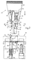
- laser head 6 comprises a nozzle 24 (shown in detail in Fig.s 2 and 3) through which beam 20 and stream 21 travel.
- Said stream 21 will be of oxygen or a similar oxidizing gas for cutting operations, or an inert gas such as argon or nitrogen for welding operations.
- Said stream of gas 21 is supplied to nozzle 24 along a pipe 25 and, according to the present invention, machine 1 comprises a servovalve 26 (controlled by a known electronic system (not shown) governing machine 1 as a whole) for selectively connecting pipe 25 to a pipe 27 supplying a first type of gas, e.g. oxidizing gas, or to a pipe 28 supplying a second type of gas, e.g. inert gas.
- Both pipes 27 and 28 are connected to appropriate pressure sources, e.g. pressurized tanks (not shown).
- Nozzle 24 comprises a top portion 30 connected to laser head 6, and a bottom end portion defined, according to the present invention, by a tip 31 designed according to the type of operation being performed and, generally speaking, the type of workpiece 2.
- Machine 1 comprises at least two tips 31 of different length and internal geometry, and selectively connectable to top portion 30 for defining the bottom portion of nozzle 24 best suited geometrically to the type of operation in question.
- the same laser head 6 may thus be employed for both cutting and welding operations by selecting, in addition to the most suitable tip 31, also the type of gas required by means of valve 26.
- the same laser head 6 may be employed for performing the same or different operations on different workpieces or portions of the same piece requiring a specific nozzle design, thus enabling the operation to be performed under the best possible conditions in a highly disturbed environment typical of laser processing (and characterised by high temperature, fumes and splash), while at the same time ensuring perfect optical, mechanical and flow concentricity of the pressurized gas.
- machine 1 for meeting the above requirements and automatically changing tips 31 on top portion 30, machine 1 according to the present invention comprises a nozzle refitting station 33 located inside work volume 5 and readily accessible by laser head 6 subsequent to displacement of the same by device 7.
- Station 33 may be installed in fixed manner inside work volume 5 (as shown in Fig.1) or, according to a variation not shown, may be installed so as to move selectively, like worktable 3, in and out of work volume 5.
- Station 33 presents at least two identical supporting devices 34 (only one of which is shown in Fig.1 and in detail in Fig.s 2 and 3) arranged, for example, side by side and each designed to support a standby tip 31.
- nozzle 24 and devices 34 present releasable means for gripping and securing tips 31 integral with nozzle 24 or one of devices 34; as well as means for selectively connecting/disconnecting said gripping means as required. Tips 31 may thus be changed by simply moving head 6 up to an empty device 34 in station 33; releasing tip 31 on to said device 34; moving head 6 over to the second device 34 supporting the other tip 31; and withdrawing said other tip 31, thus leaving said second device 34 empty for receiving back the withdrawn tip 31.
- Nozzle 24, and consequently also component elements 30 and 31, must also be designed to function as a capacitive sensor, for controlling adaptive displacement by slide 18 and so maintaining nozzle 24 at the same distance from the surface of workpieces 2 presenting minor surface defects, such as puckering caused by local distortion of workpieces 2 of relatively thin sheet metal.
- connecting portion 30 presents an external inductor 36 protected by a cap 37 and connected, for example, to a known resonant LC circuit (not shown) in turn connected to the electronic system controlling machine 1. Provision must therefore be made for ensuring optimum contact of elements 30 and 31, and connection of the same for sufficiently reproducing the electrical characteristics of nozzle 24 as a whole whenever the same tip 31 is removed and replaced.
- tips 31 are selectively connectable to element 30 by means of respective bayonet connectors 40 and 41 connected/disconnected by a system on machine 1 consisting of means enabling selective rotation and relative travel of nozzle 24 and devices 34.
- station 33 may present a motor 43 for selectively rotating supporting devices 34 about an axis parallel to the axis of symmetry of nozzle 24 when this is positioned facing and coaxial with one of devices 34 by means of three-axis positioning device 7. In this case, relative travel is achieved by device 7, but it may also be achieved by motor 43 moving devices 34.
- relative displacement for connecting/disconnecting connectors 40 and 41 is controlled directly by the system governing head 6, and using, in addition to device 7, also rotary couplings 14 and 15, i.e. the two additional numerical control axes provided on machine 1 according to the present invention and which are absent on most standard robot handling devices.
- each tip 31 presents a first and second series of external radial tabs 45 and 46, both equally spaced in a ring.
- Tabs 45 are designed to cooperate with a series of respective L-shaped teeth 47 projecting frontwards and equally spaced in a ring about the bottom end 48 of portion 30 of nozzle 24, preferably secured to portion 30 in removable manner by means of a threaded coupling projecting from cap 37.
- Tabs 46 are designe to cooperate with a second series of respective L-shaped teeth 49 similar to 47 and equally spaced in a ring inside a seat 50 on each supporting device 34 in station 33.
- End 48 supports a ring 52 designed to slide parallel to teeth 47 and against the action of elastic means defined by a helical spring 51 housed inside cap 37.
- Ring 52 comprises a series of axial tabs 53 (only one of which is shown in Fig.s 2 and 3) equally spaced in a ring so as to slide between adjacent teeth 47; and an annular shoulder 54 designed to contact edge 55 of seat 50 on each supporting device 34.
- Spring 51 which is inserted between ring 52 and a shoulder 56, normally maintains ring 52 in the extracted position contacting a shoulder 57 formed on end 48 at the base of teeth 47, and wherein tabs 53 are inserted between and substantially over the full height of teeth 47.
- a pin 59 designed to slide axially between and parallel to adjacent teeth 49 against the action of a helical spring 60 housed inside a recess 61 formed at the base of seat 50 and closed by a threaded cap 62.
- pin 59 cooperates head-on with a pin 64 housed, in sliding manner and projecting from edge 55, inside a hole 65 formed adjacent to seat 50.
- Said pin 64 (Fig.3) cooperates frontally with a shoulder surface 66 on portion 30 of nozzle 24, designed to receive interchangeable tip 31 and, in the example shown, defined by the front surface of cap 37.
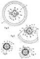
- tabs 45 and 46 of each tip 31 are four in number, and so shaped and arranged as to form a Maltese cross (plan view). To ensure a constant angular position of tip 31 in relation to connecting portion 30, and so guarantee the repeatability of the electromagnetic characteristics of nozzle 24 as ta whole, each series of tabs 45 and 46 comprises a respective smaller tab 45 a and 46 a . Similarly, each series of teeth 47 and 49 comprises a tooth having lateral internal check pin numbered 77 and 79 respectively. Finally, it should be noted that, whereas tabs 45 and 46 present the same angular position, teeth 47 and 49 are angularly offset by an amount equal to the tab pitch, in the example shown, by 45°.
- Machine 1 as described above operates as follows.
- station 33 supports, for example, two different tips 31, one for welding and the other for cutting, and each supported on a device 34; head 6 presents only portion 30 of nozzle 24; tabs 46 are engaged beneath teeth 49; and pin 79 and pin 59, which is maintained by spring 60 in the extracted position between two teeth 49, prevent rotation of tips 31 by virtue of arresting tabs 46.
- machine 1 moves head 6 up to one of devices 34 to withdraw the tip 31 required for the operation in question.
- Head 6 is positioned with portion 30 coaxial with tip 31 by the numerical control positioning systems on machine 1, in that station 33 is located inside work volume 5 and its coordinates memorised in the electronic control system governing machine 1.
- withdrawal is effected by traversing and relatively rotating, in the appropriate direction, tip 31 on device 34 and nozzle portion 30.
- This may be effected by rotating and traversing device 34 or, as in the example shown, using the powered head control devices (device 7 and rotary couplings 14 and 15), i.e. by maintaining device 34 stationary and moving only nozzle portion 30.
- head 6 is lowered for inserting projecting end 48 inside seat 50.
- nozzle 24 is simply set to the Fig.2 position and lowered towards devices 34 for inserting tip 31 inside seat 50. As in the previous case, downward movement of nozzle 24 results in withdrawal of pin 59 and ring 52, thus positioning nozzle 24 and device 34 as shown in Fig.3. At this point, portion 30 is rotated in the opposite direction, as shown by the arrows in Fig.s 4 and 7.
- tip 31, which is rotated by end portion 48 by virtue of pin 77 cooperating with tab 45 a (Fig.7) causes tabs 46 to engage teeth 49 (Fig.4), subsequent to which, tab 46 a contacts pin 79, thus preventing rotation of tip 31. Further 45° rotation of end portion 48 therefore releases tabs 45 from teeth 47 (Fig.6).
- machine 1 provides for switching fully automatically, and without stopping the machine, from welding to cutting operations or vice versa, as well as for adapting the geometry of the nozzle to that of the workpiece (or portions of the same) within the same operation.
- Machine 1 according to the present invention therefore provides for a high degree of versatility combined with low cost and a high degree of reliability.
Landscapes
- Physics & Mathematics (AREA)
- Optics & Photonics (AREA)
- Engineering & Computer Science (AREA)
- Plasma & Fusion (AREA)
- Mechanical Engineering (AREA)
- Laser Beam Processing (AREA)
Claims (9)
- Laser-Arbeitsmaschine zur Durchführung mechanischer Operationen, speziell zum Schneiden und Schweißen, wobei die Arbeitsmaschine folgende Einrichtungen umfaßt: einen Laserkopf (6) mit einer Düse (24), die einen Laserstrahl und einen Strom von für die durchgeführte Operation geeignetem Gas liefert und einen entfernbaren Endteil (31) aufweist, der in Abhängigkeit von der Art der durchzuführenden Operation konstruiert ist; eine Einrichtung (4) zum Bewegen des Laserkopfs (6) relativ im Raum innerhalb eines gegebenen Arbeitsraums (5) in Bezug zu wenigstens einem Werkstück (2); und eine Einrichtung zum selektiven und automatischen Wechseln des entfernbaren Endteils (31) der Düse (24);
dadurch gekennzeichnet, daß diese Einrichtungen folgende Teile umfassen:(i) eine Düsen-Tauschfassung-Station (33), die vom Kopf (6) unabhängig ist und innerhalb des Arbeitsraums angeordnet werden kann, mit wenigstens zwei Tragvorrichtungen (34) für jeweilige Düsenspitzen (31) unterschiedlicher Konstruktion, die jedoch beide selektiv zu einem Zustand integral mit der Düse (24) anbringbar sind, um deren entfernbaren Endteil zu ergeben;(ii) erste Bajonettverbinder (40) zum selektiven Verbinden der Düsenspitzen (31) mit der Düse (24) und zweite Bajonettverbinder (41) zum selektiven Verbinden der Düsenspitzen (31) mit jeweils einer der Tragvorrichtungen (34) der Tauschfassung-Station;(iii) eine Einrichtung (77, 79; 53, 47; 59, 49) zum selektiven lösbaren winkelmäßigen Verbinden der Düsenspitzen (31) mit der Düse (24) bzw. mit der Tragvorrichtung (34) zum Herstellen einer winkelmäßigen gegenseitigen Starre der Düsenspitzen (31) mit jenen in einer einzigen vorgegebenen Winkelrichtung; und(iv) eine Steuereinrichtung (4, 14, 15, 43) zum Verdrehen und zur relativen Querbewegung der Düse (24) und der Tragvorrichtungen (34) in die vorgegebene Winkelrichtung. - Arbeitsmaschine nach Anspruch 1, dadurch gekennzeichnet, daß die Steuereinrichtung wenigstens einen Motor (43) zum selektiven Verdrehen der Tragvorrichtungen (34) um eine Achse parallel zur Symmetrieachse der Düse (24) umfaßt.
- Arbeitsmaschine nach Anspruch 1, dadurch gekennzeichnet, daß die Steuereinrichtung die Einrichtung zum Bewegen des Laserkopfs (6) innerhalb des Arbeitsraums umfaßt; wobei diese Einrichtung eine Vorrichtung (7) zum Bewegen des Laserkopfs (6) entlang drei kartesischen Achsen und jeweilige angetriebene Kupplungen (14, 15) zum Drehen des Laserkopfs (6) um zwei aufeinander senkrechte Achsen, die parallel zu zwei der drei kartesischen Achsen liegen, aufweist.
- Arbeitsmaschine nach Anspruch 2 oder 3, dadurch gekennzeichnet, daß jede Spitze (31) eine erste und eine zweite Reihe von äußeren radialen Vorsprüngen (45, 46) aufweist; daß die Vorsprünge in jeder dieser Reihen in gleichmäßigen Abständen in einem Ring angeordnet sind und unterhalb einer ersten und einer zweiten Reihe von L-förmigen Zähnen (47, 49) zusammenwirken, die nach vorne und jeweils in gleichen Abständen in einem Ring um einen Teil (30), der die Düse (24) mit dem Laserkopf (6) verbindet, und in einen Sitz (50) an jeder Tragvorrichtung (34) der Station (33) vorstehen.
- Arbeitsmaschine nach Anspruch 4, dadurch gekennzeichnet, daß der die Düse (24) mit dem Laserkopf (6) verbindende Teil (30) einen Ring (52) trägt, der parallel zur ersten Reihe von Zähnen (47) entgegen der Wirkung einer elastischen Einrichtung (51) gleitet und eine Reihe von axialen Vorsprüngen (53) umfaßt, die unter gleichmäßigen Abständen in einem Ring angeordnet sind und jeweils dazu konstruiert sind, zwischen benachbarten Zähnen (47) in der ersten Reihe zu gleiten; und eine ringförmige Schulter (54) trägt, die dazu konstruiert ist, den Rand (55) des Sitzes (50) auf jeder der Tragvorrichtungen (34) anschließend an die relative Verschiebung der Tragvorrichtung (34) in Bezug zur Düse (24) zu berühren und so den Ring (52) um einen ausreichenden Betrag zurückzuschieben, um ein Angreifen der Zähne (47) an dem verbindenden Teil (30) der Düse (24) und der ersten Reihe von Vorsprüngen (45) an dieser Spitze (31) zu ermöglichen.
- Arbeitsmaschine nach Anspruch 4 oder 5, dadurch gekennzeichnet, daß sich innerhalb jedes Sitzes (50) und zwischen zweien der Zähne (49) in der zweiten Reihe ein Stift (59) befindet, der dazu konstruiert ist, axial parallel zu den Zähnen (49) entgegen der Wirkung einer zweiten elastischen Einrichtung (60) zu gleiten, und der am entgegengesetzten Ende mit einem gleitenden Stift (64) kooperiert, der seinerseits anschließend an die relative Verschiebung der Düse (24) in Bezug zum Sitz (50) frontal mit einer Schulterfläche (66) des verbindenden Teils (30) der Düse (24) zusammenwirkt, um so den Stift um einen ausreichenden Betrag zurückzuschieben, um ein Angreifen der Zähne (49) am Sitz (50) an der zweiten Reihe von Vorsprüngen (46) an der Spitze (31) zu ermöglichen.
- Arbeitsmaschine nach Anspruch 5 oder 6, dadurch gekennzeichnet, daß die Vorsprünge in der ersten und in der zweiten Reihe so angeordnet sind, daß sie ein Malteserkreuz bilden; wobei jede der Reihen von Vorsprüngen einen kleineren Vorsprung (45a, 46a) umfaßt und jede der Reihen von Zähnen einen Zahn mit einem inneren seitlichen Verriegelungsstift (77, 79) aufweist.
- Arbeitsmaschine nach Anspruch 7, dadurch gekennzeichnet, daß der verbindende Teil (30) der Düse (24) einen externen Induktor (36) aufweist, der ermöglicht, daß die Düse (24) als kapazitiver Sensor wirkt; wobei der Laserkopf (6) an einem angetriebenen Schlitten (18) montiert ist, der eine adaptive Bewegung des Laserkopfs (6) entlang seiner Symmetrieachse ermöglicht.
- Arbeitsmaschine nach einem der vorhergehenden Ansprüche, dadurch gekennzeichnet, daß sie ein Ventil (26) zum selektiven Anschließen eines Rohrs (25), das ein Strömungsmittel an die Düse (24) liefert, an wenigstens eine erste und eine zweite Rohrleitung (27, 28), die ein erstes und ein zweites Gas liefern, umfaßt.
Applications Claiming Priority (2)
| Application Number | Priority Date | Filing Date | Title |
|---|---|---|---|
| IT8967654A IT1233073B (it) | 1989-08-01 | 1989-08-01 | Macchina laser per l effettuazione di lavorazioni di taglio e saldatu ra |
| IT6765489 | 1989-08-01 |
Publications (3)
| Publication Number | Publication Date |
|---|---|
| EP0411535A2 EP0411535A2 (de) | 1991-02-06 |
| EP0411535A3 EP0411535A3 (en) | 1991-03-27 |
| EP0411535B1 true EP0411535B1 (de) | 1994-04-20 |
Family
ID=11304256
Family Applications (1)
| Application Number | Title | Priority Date | Filing Date |
|---|---|---|---|
| EP90114588A Expired - Lifetime EP0411535B1 (de) | 1989-08-01 | 1990-07-30 | Laser-Arbeitsmaschine zum Schneiden und Schweissen |
Country Status (4)
| Country | Link |
|---|---|
| US (1) | US5101089A (de) |
| EP (1) | EP0411535B1 (de) |
| DE (1) | DE69008265T2 (de) |
| IT (1) | IT1233073B (de) |
Families Citing this family (14)
| Publication number | Priority date | Publication date | Assignee | Title |
|---|---|---|---|---|
| DE19944484C1 (de) | 1999-09-16 | 2001-04-19 | Precitec Gmbh | Wechselvorrichtung für einen Linsenhalter eines Anschlusskopfs zur Bearbeitung eines Werkstücks mittels eines Laserstrahls |
| DE10056330C1 (de) * | 1999-09-16 | 2002-03-07 | Precitec Kg | Wechselvorrichtung für einen Linsenhalter eines Anschlußkopfs zur Bearbeitung eines Werkstücks mittels eines Laserstrahls |
| EP1459835B1 (de) | 2003-03-15 | 2013-04-24 | TRUMPF Werkzeugmaschinen GmbH + Co. KG | Laserbearbeitungsverfahren mit einem Laserbearbeitungskopf zum Laserschneiden und zum Laserschweissen |
| DE50312360D1 (de) * | 2003-08-09 | 2010-03-11 | Trumpf Werkzeugmaschinen Gmbh | Laserbearbeitungsdüsenkupplung |
| US7141758B2 (en) * | 2003-10-01 | 2006-11-28 | Trumpf, Inc. | Laser processing installation with readily accessible cutting unit |
| DE202004021568U1 (de) * | 2004-10-20 | 2009-04-23 | Robot-Technology Gmbh | Roboter |
| EP1905530B1 (de) * | 2006-09-29 | 2013-06-05 | TRUMPF Werkzeugmaschinen GmbH + Co. KG | Laserbearbeitungskopf mit einer Dichtungsanordnung |
| EP2020541B1 (de) * | 2007-08-01 | 2010-01-13 | Carl Freudenberg KG | Verfahren zur Herstellung eines Dichtrings |
| US8373085B2 (en) * | 2009-05-28 | 2013-02-12 | The Viking Corporation | Pipe fabrication equipment |
| US9492990B2 (en) * | 2011-11-08 | 2016-11-15 | Picosys Incorporated | Room temperature glass-to-glass, glass-to-plastic and glass-to-ceramic/semiconductor bonding |
| JP6904810B2 (ja) * | 2017-06-29 | 2021-07-21 | コマツ産機株式会社 | レーザ加工機 |
| EP3693125B1 (de) * | 2017-10-06 | 2022-02-09 | Amada Holdings Co., Ltd. | Laserverarbeitungsverfahren und -vorrichtung |
| JP6577110B2 (ja) | 2017-10-06 | 2019-09-18 | 株式会社アマダホールディングス | レーザ加工方法及びレーザ加工装置 |
| DE102024126772A1 (de) * | 2024-09-17 | 2026-03-19 | Kjellberg-Stiftung, rechtsfähige Stiftung des bürgerlichen Rechts | Bearbeitungskopf zur thermischen und/oder mechanischen Bearbeitung von Werkstücken, Anordnung mit demselben sowie Verfahren zum Verbinden und Trennen eines vorderen und eines hinteren Teils eines Bearbeitungskopfes |
Family Cites Families (9)
| Publication number | Priority date | Publication date | Assignee | Title |
|---|---|---|---|---|
| US4031351A (en) * | 1972-10-25 | 1977-06-21 | Groupement Atomique Alsacienne Atlantique | High energy laser beam cutting method and apparatus |
| JPS5924582A (ja) * | 1982-08-02 | 1984-02-08 | Osaka Denki Kk | 自動溶接機におけるガスノズル交換方法及びその装置 |
| DE3410913A1 (de) * | 1984-03-24 | 1985-10-03 | Trumpf GmbH & Co, 7257 Ditzingen | Werkzeugmaschine zur mechanischen und laserstrahl-bearbeitung eines werkstuecks |
| US4836706A (en) * | 1985-02-08 | 1989-06-06 | Rogers Tool Works, Inc. | Quick change tool holder |
| DK168593B1 (da) * | 1985-05-09 | 1994-05-02 | Aga Ab | Fremgangsmåde ved laserskæring af metalliske emner |
| US4661680A (en) * | 1985-06-28 | 1987-04-28 | Westinghouse Electric Corp. | End-of-arm tooling carousel apparatus for use with a robot |
| IT1196856B (it) * | 1986-12-19 | 1988-11-25 | Fiat Auto Spa | Procedimento di lavorazione di grandi stampi in ghisa particolarmente per lo stampaggio di lamiere di veicoli ed attrezzature per la sua realizzazione |
| DE3735598A1 (de) * | 1987-10-21 | 1989-05-11 | Messer Griesheim Gmbh | Verfahren und einrichtung zum automatischen wechseln von schneidduesen |
| US4782496A (en) * | 1987-11-05 | 1988-11-01 | United Technologies Corporation | Breakaway nozzle for a laser processing machine |
-
1989
- 1989-08-01 IT IT8967654A patent/IT1233073B/it active
-
1990
- 1990-07-30 EP EP90114588A patent/EP0411535B1/de not_active Expired - Lifetime
- 1990-07-30 US US07/559,054 patent/US5101089A/en not_active Expired - Fee Related
- 1990-07-30 DE DE69008265T patent/DE69008265T2/de not_active Expired - Fee Related
Also Published As
| Publication number | Publication date |
|---|---|
| DE69008265T2 (de) | 1994-08-11 |
| DE69008265D1 (de) | 1994-05-26 |
| IT8967654A0 (it) | 1989-08-01 |
| EP0411535A2 (de) | 1991-02-06 |
| EP0411535A3 (en) | 1991-03-27 |
| US5101089A (en) | 1992-03-31 |
| IT1233073B (it) | 1992-03-14 |
Similar Documents
| Publication | Publication Date | Title |
|---|---|---|
| US5101089A (en) | Laser machine for cutting and welding | |
| US7013544B2 (en) | Machine tool and pallet changer for machine tool | |
| CA1197081A (en) | Workpiece storage and shuttle apparatus | |
| EP3733341B1 (de) | Werkzeugmagazin einer werkzeugmaschine | |
| EP3907038B1 (de) | Werkzeugmaschine und verfahren zu deren betrieb | |
| CN113508006A (zh) | 自动刀具更换装置与其的控制方法以及包含其的机床 | |
| US20230201941A1 (en) | Wire Electrical Discharge Machine | |
| WO2013089860A1 (en) | Method and apparatus cutting a mill plate | |
| EP0093575A2 (de) | Verfahren zum Betreiben einer Werkzeugmaschine | |
| EP1673198B1 (de) | Laserbearbeitungsanlage mit c-förmigem rahmen und laserschneidgerät mit ruhestellung | |
| US12623302B2 (en) | Machine tool | |
| US12403562B2 (en) | Cooling lubricant nozzle carrier for a grinding machine, grind-ing machine having such a cooling lubricant nozzle carrier, and method for operating a cooling lubricant nozzle carrier | |
| JP2968814B2 (ja) | 型彫放電加工機の加工槽装置 | |
| KR20210129478A (ko) | 공작기계의 스핀들 클램핑 장치 | |
| US12257660B2 (en) | Machine tool cable protection device | |
| KR102874754B1 (ko) | 공작기계의 가공 제어장치 및 이의 제어방법 | |
| JP2002178186A (ja) | レーザ加工システム及びこのレーザ加工システムを用いたレーザ加工方法 | |
| EP1759804A1 (de) | Laser-Bearbeitungsmaschine mit einer eine Düse polierenden Einrichtung | |
| KR20220142222A (ko) | 공작기계의 공구 거치장치 | |
| JPS57135734A (en) | Numerically controlled cutting machine for glass plate | |
| JP3156248B2 (ja) | ワイヤ放電加工機と細穴放電加工機に適用できる加工台装置 | |
| GB2135604A (en) | Machine tool workpiece storage to worktable shuttle apparatus | |
| CN220698324U (zh) | 一种自动cnc加工设备 | |
| JPH0748356Y2 (ja) | 工具交換装置 | |
| JP2844488B2 (ja) | フレキシブルマニファクチャリングシステムに使用可能なパレット |
Legal Events
| Date | Code | Title | Description |
|---|---|---|---|
| PUAI | Public reference made under article 153(3) epc to a published international application that has entered the european phase |
Free format text: ORIGINAL CODE: 0009012 |
|
| AK | Designated contracting states |
Kind code of ref document: A2 Designated state(s): BE CH DE ES FR GB IT LI NL SE |
|
| PUAL | Search report despatched |
Free format text: ORIGINAL CODE: 0009013 |
|
| AK | Designated contracting states |
Kind code of ref document: A3 Designated state(s): BE CH DE ES FR GB IT LI NL SE |
|
| 17P | Request for examination filed |
Effective date: 19910918 |
|
| 17Q | First examination report despatched |
Effective date: 19920514 |
|
| GRAA | (expected) grant |
Free format text: ORIGINAL CODE: 0009210 |
|
| AK | Designated contracting states |
Kind code of ref document: B1 Designated state(s): BE CH DE ES FR GB IT LI NL SE |
|
| PG25 | Lapsed in a contracting state [announced via postgrant information from national office to epo] |
Ref country code: IT Free format text: LAPSE BECAUSE OF FAILURE TO SUBMIT A TRANSLATION OF THE DESCRIPTION OR TO PAY THE FEE WITHIN THE PRE;WARNING: LAPSES OF ITALIAN PATENTS WITH EFFECTIVE DATE BEFORE 2007 MAY HAVE OCCURRED AT ANY TIME BEFORE 2007. THE CORRECT EFFECTIVE DATE MAY BE DIFFERENT FROM THE ONE RECORDED.SCRIBED TIME-LIMIT Effective date: 19940420 Ref country code: SE Free format text: THE PATENT HAS BEEN ANNULLED BY A DECISION OF A NATIONAL AUTHORITY Effective date: 19940420 Ref country code: CH Effective date: 19940420 Ref country code: NL Effective date: 19940420 Ref country code: ES Free format text: THE PATENT HAS BEEN ANNULLED BY A DECISION OF A NATIONAL AUTHORITY Effective date: 19940420 Ref country code: LI Effective date: 19940420 Ref country code: BE Effective date: 19940420 |
|
| REF | Corresponds to: |
Ref document number: 69008265 Country of ref document: DE Date of ref document: 19940526 |
|
| ET | Fr: translation filed | ||
| PGFP | Annual fee paid to national office [announced via postgrant information from national office to epo] |
Ref country code: GB Payment date: 19940714 Year of fee payment: 5 |
|
| PGFP | Annual fee paid to national office [announced via postgrant information from national office to epo] |
Ref country code: DE Payment date: 19940716 Year of fee payment: 5 |
|
| PGFP | Annual fee paid to national office [announced via postgrant information from national office to epo] |
Ref country code: FR Payment date: 19940718 Year of fee payment: 5 |
|
| REG | Reference to a national code |
Ref country code: CH Ref legal event code: PL |
|
| NLV1 | Nl: lapsed or annulled due to failure to fulfill the requirements of art. 29p and 29m of the patents act | ||
| PLBE | No opposition filed within time limit |
Free format text: ORIGINAL CODE: 0009261 |
|
| STAA | Information on the status of an ep patent application or granted ep patent |
Free format text: STATUS: NO OPPOSITION FILED WITHIN TIME LIMIT |
|
| 26N | No opposition filed | ||
| PG25 | Lapsed in a contracting state [announced via postgrant information from national office to epo] |
Ref country code: GB Effective date: 19950730 |
|
| GBPC | Gb: european patent ceased through non-payment of renewal fee |
Effective date: 19950730 |
|
| PG25 | Lapsed in a contracting state [announced via postgrant information from national office to epo] |
Ref country code: DE Effective date: 19960402 |
|
| PG25 | Lapsed in a contracting state [announced via postgrant information from national office to epo] |
Ref country code: FR Effective date: 19960430 |
|
| REG | Reference to a national code |
Ref country code: FR Ref legal event code: ST |
|
| REG | Reference to a national code |
Ref country code: FR Ref legal event code: ST |
|
| REG | Reference to a national code |
Ref country code: FR Ref legal event code: ST |