EP0410484A1 - Procédé pour adapter l'intensité lumineuse totale à l'intensité lumineuse extérieure - Google Patents
Procédé pour adapter l'intensité lumineuse totale à l'intensité lumineuse extérieure Download PDFInfo
- Publication number
- EP0410484A1 EP0410484A1 EP90114487A EP90114487A EP0410484A1 EP 0410484 A1 EP0410484 A1 EP 0410484A1 EP 90114487 A EP90114487 A EP 90114487A EP 90114487 A EP90114487 A EP 90114487A EP 0410484 A1 EP0410484 A1 EP 0410484A1
- Authority
- EP
- European Patent Office
- Prior art keywords
- light
- light intensity
- room
- outside
- function
- Prior art date
- Legal status (The legal status is an assumption and is not a legal conclusion. Google has not performed a legal analysis and makes no representation as to the accuracy of the status listed.)
- Granted
Links
Images

Classifications
-
- H—ELECTRICITY
- H05—ELECTRIC TECHNIQUES NOT OTHERWISE PROVIDED FOR
- H05B—ELECTRIC HEATING; ELECTRIC LIGHT SOURCES NOT OTHERWISE PROVIDED FOR; CIRCUIT ARRANGEMENTS FOR ELECTRIC LIGHT SOURCES, IN GENERAL
- H05B41/00—Circuit arrangements or apparatus for igniting or operating discharge lamps
- H05B41/14—Circuit arrangements
- H05B41/36—Controlling
- H05B41/38—Controlling the intensity of light
- H05B41/39—Controlling the intensity of light continuously
- H05B41/392—Controlling the intensity of light continuously using semiconductor devices, e.g. thyristor
- H05B41/3921—Controlling the intensity of light continuously using semiconductor devices, e.g. thyristor with possibility of light intensity variations
- H05B41/3922—Controlling the intensity of light continuously using semiconductor devices, e.g. thyristor with possibility of light intensity variations and measurement of the incident light
-
- H—ELECTRICITY
- H05—ELECTRIC TECHNIQUES NOT OTHERWISE PROVIDED FOR
- H05B—ELECTRIC HEATING; ELECTRIC LIGHT SOURCES NOT OTHERWISE PROVIDED FOR; CIRCUIT ARRANGEMENTS FOR ELECTRIC LIGHT SOURCES, IN GENERAL
- H05B39/00—Circuit arrangements or apparatus for operating incandescent light sources
- H05B39/04—Controlling
- H05B39/041—Controlling the light-intensity of the source
- H05B39/042—Controlling the light-intensity of the source by measuring the incident light
Definitions
- the invention relates to a method for adapting the luminous intensity of the total light according to the preamble of claim 1.
- Methods of this type are used to compensate for fluctuations in light intensity in a room caused by changing outside light.
- an outside light sensor is arranged outside the room to be illuminated.
- An external light-dependent control of the light intensity of the interior light takes place in opposite directions; with decreasing outside light, the interior light of the room is controlled brighter.
- a light-sensitive sensor part is connected to a control part, which in turn controls a dimmer circuit part.
- the dimmer circuit part controls light sources arranged in the room, which generate a dimmed light level.
- the light-sensitive sensor part is arranged so that it cannot detect the dimmed light level of the light sources.
- the light sources are controlled in accordance with a linear, opposing dependence of the dimmed light level on the sensed sensor signal. The inclination of this function, which defines the dependence, is set by a gradient factor.
- the setting is made at any time of day when the lighting arrangement is started up.
- Such a method has the disadvantage that not only the dimmed light level present at the time of the adjustment is changed with the setting of the slope of the linear function, but also the dimmed light levels assigned to all other light intensities of the outside light are changed.
- the invention is based on the object of specifying a method and a circuit arrangement in which there are refined setting options for adapting the light intensity in a room.
- the object is achieved in a method of the type mentioned at the outset in that the dependency function is determined by a plurality of function values which can be set independently of one another and in that each function value can be changed independently of other function values.
- the invention makes use of the consideration that an individual lighting requirement is not met by specifying a single parameter of the function, for example the slope or the parallel displacement, but that this can only be met by specifying the function individually or in sections.
- the invention makes use of the knowledge that even a complicated dependency of the light intensity of the interior light on the light intensity of the exterior light, the total light or the time can be determined independently by relatively few Lets define function values. Thus, with individual ease of use, all individual lighting requirements are taken into account.
- Claim 6 is directed to the adaptation of the structural illumination of a room, which can not only be dependent on the outside light intensity but also on the direction of the daylight. According to the invention, the distribution of the light intensity in the room can be adjusted depending on the daylight, so that a certain, if necessary, uneven light distribution can be realized in the room.
- An observer present in a room perceives the sum of the luminous intensity of the incident external light E ' i and the artificially generated internal light E k as the total luminous intensity of the summed light E i .
- the person present in the room can now, according to the characterizing part of claim 1, on the one hand at any time of the day and on the other hand at any light ratio a corresponding light intensity of the interior light and thus the light intensity of the total light. that is, choose the interior brightness without the person itself being burdened with the actual function of the dependency. According to the invention, this function is determined by selecting individual points.
- the invention is explained in more detail below on the basis of exemplary embodiments.
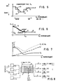
- FIG. 1 shows an exemplary embodiment of the invention with an outside light sensor 1, a dimmer circuit part 3 and light sources 5, 6, 7 which can be connected to this.
- the dimmer circuit part 3 has a control circuit part 2, a non-volatile read / write memory 8 and a plurality of dimmers 4, only one of which is shown to explain the mode of operation.
- Several lighting units can be provided in one room, each of which is controlled by the outside light (common outside light sensor) according to a different function.
- the different functions are stored in the preferably shared read / write memory 8.
- the outside light sensor 1 emits a light intensity-dependent control signal to the control circuit part 2, which in turn emits a predetermined phase control signal to the dimmer 4 according to defined values 11 in the memory 8, as a result of which the light intensity of the light sources 5, 6, 7 is set.
- Filament lamps 5, gas discharge lamps 6 or arc lamps 7 can be used as light sources, for example.
- electronic ballasts electronic ballasts
- the dimming function of which can be varied by varying their output frequency and / or their output duty cycle.
- FIG. 2 shows with curve shape a) a linearly falling light intensity of the interior light with increasing light intensity of the exterior light.
- a person present in the room can adjust a total luminous intensity E i by adjusting the slope or shift of the function a) in E k or in E a direction, which is constant, for example.
- a light intensity curve of the interior light according to curve c) is selected, there is also an area with increasing exterior brightness E a in which the intensity of the interior light E k is approximately proportional (concurrent) to the intensity of the exterior light E a .
- the double arrows marked on the functions a), b), c), c1), c2), c3) indicate a possibility of moving and changing them to adapt the desired function sequences. If individual points of the function curve c) or of the function curves c1), c2) or c3) are defined individually and independently of one another and stored in the memory 8, then a precise repeatability of a function once defined is possible.
- FIGS. 2, 3 and 6 are drawn continuously and continuously, one point-by-point storage and complete definition would require an infinite number of points. If, according to FIG. 5, a desired dependency ratio is now defined by a finite number of values 11, an interpolation to be determined beforehand specifies how the continuous function course controlling the light intensity is generated.
- FIG. 4 shows a light intensity function curve as a function of the time of day.
- the light intensity of the interior light E k and the times at which the desired and preset light intensities of the interior light are switched on can be recognized by the step-like function.
- An observer in a room now has the visual impression of outside light coming in through glass surfaces and the time-dependent controlled lamp light. For a specific day and a given weather ratio creates the individually desired room brightness or light intensity.
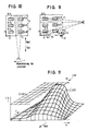
- FIG. 6 shows a special case of a light intensity curve E k of the interior light with a constant minimum.
- a light intensity curve as shown, would already be satisfactorily approachable with five values 12 in the case of linear interpolation.
- the lamp light intensity is basically (rough setting) controlled in a time-dependent manner, ie certain light levels are assigned basic light intensities, the fine adjustment in the direction of the double arrows in FIG. 4 is controlled by the light intensity of the outside light.
- the two dependencies can be interchanged, the basic light intensity is specified depending on the outside light, the fine influence on the light intensity E k takes place depending on the time. This results in a simplified possibility for an operator to influence.
- FIG. 8 shows a further exemplary embodiment of the invention with an outside light sensor 1-1, a dimmer circuit part 3 and a plurality of light sources 5-1, 5-2, 5-3 and 5-4 which can be connected to this.
- the dimmer circuit part 3 has a control circuit part 2, a non-volatile read-write memory 8 and a plurality of dimmers 4-1, 4-2, 4-3 and 4-4.
- the control circuit part 2 is supplied with a control signal emitted by the outside light sensor 1-1 and each connectable light source, for example 5-4, is provided by a dimmer, for example wise 4-4, controlled.
- the control circuit part 2 is in one piece here, but can be designed in four parts for the control of the four dimmers 4-1, 4-2, 4-3, 4-4; these four control circuit parts are then controlled by a single outside light sensor 1-1 parallel to the input. Furthermore, a plurality of dimmer circuit parts 3-1, 3-2, 3-3 and 3-4 can also be used to control each of an interior light generator according to FIG. 1, the control signal emitted there by the exterior light sensor 1 being supplied to the plurality of dimmer circuit parts in parallel with the input. It goes without saying that the restriction to four dimmers or four dimmer circuit parts here is only of an exemplary nature; any number of dimmer circuit parts or dimmers with a corresponding number of interior light generators can be used.
- the non-volatile read-write memory 8 contains a multiplicity of values 11, 12 which define a plurality of functions c1, c2, c2, c4, c5 which can be changed independently of one another.
- the control signal which the outside light sensor 1-1 emits and which is supplied to the control circuit part (s) 2, 2-1, 2-2, 2-3, and 2-4 depending on four, the Variety of values 11, 12 defined different functions supplied to the four dimmers 4-1, 4-2, 4-3, 4-4 different predetermined phase control signals.
- the different functions for the control of the respective dimmer or interior light generator are stored together in the one non-volatile read / write memory 8.
- the multiple functions allow independent control of the interior light generators that can be installed in a room at different locations 5-1, 5-2, 5-3 or 5-4.
- All the control circuit parts 2-1, 2-2, 2-3, 2-4 which control the dimmers 4-1, 4-2, 4-3 or 4-4 receive the same light-intensity-dependent signal from the outside light sensor 1-1.
- a variant of the embodiment of FIG. 8 is that instead of the one outside light sensor 1-1, several outside light sensors, in the present case four outside light sensors 1-1, 1-2, 1-3 and 1-4, the four control circuit parts 2-1, Control 2-2, 2-3 or 2-4.
- An outside light sensor, for example 1-2 controls a control shading part, for example 2-2.
- Such a multidimensional arrangement can also be implemented by means of several different dimmer circuit parts 3-1, 3-2, 3-3 or 3-4.
- one dimmer circuit part, for example 3-1 is controlled by an outside light sensor, for example 1-1.
- the light intensity of the interior light can be influenced by the circuit arrangement according to FIG. 8 in the same way as, for example was shown in Figure 5.
- the nonlinearities occurring in the dimmer 4 ie the dependence of the light intensity of the interior light level on the ignition angle ⁇ (mains voltage phase gating angle) of the dimmer or the output frequency of an electronic ballast (EVG), were not mentioned in particular for the sake of clarity. However, these are taken into account by the control circuit part 2 when calculating, storing and changing light intensity values in the memory 8.
- FIGS. 9 and 10 each show the same room which has windows F1, F2 and F3, through which outside light E a can fall into said room E i '. At the same time, cardinal points are shown. Windows F1 and F2 are on the east side, window F3 is on the south side.
- six interior light generators (artificial light generators) 6-5, 6-6, 6-7, 6-8, 6-9 and 6-10 are attached to the ceiling in a symmetrical arrangement.
- a pair of sensors 1-5 and 1-6 is arranged in the southeast corner in FIG. 9, by means of which both the outside light intensity E a and its direction can be detected.
- FIG. 8 An x / y coordinate system is shown in the southwest corner, which illustrates the spatial dependence in space and corresponds to the x / y coordinate system of FIG. 11.
- six independently controllable dimmer circuit parts 4-5, 4-6, .... 4-10 are therefore to be provided.
- two independent exterior light sensors 1-5, 1-6 the first of which is in the east direction and the last one direction south oriented in, is provided, so a common control circuit part 2 can be provided, which from the outside direction of light and the external light luminance E a brightness values E k depending from the memory 8 individually supplies the six dimmer circuit parts for the six dimmer circuit parts. 4
- gas discharge lamps 6 are shown in FIGS. 9 and 10, as are preferably used for ceiling-mounted individual lighting or light band applications with frequency-controlled electronic ballasts (EVG).
- EDG electronic ballasts
- an additional interior light illumination (artificial light) E k (x, y) can now be generated in the room depending on the light intensity and the light direction in amplitude E k and location dependence x, y is chosen such that it complements the respective light E i ′ forms.
- the light 6-6 and the lamp 6-9 would have to be switched on or the brightness increased, for example, in the case of the incident light, the remaining four lamps could be switched off or reduced (dimmed) to a lower brightness value.
- This enables uniform daytime and season-independent room lighting E i (x, y) and saves energy at the same time.
- FIG. 11 shows the spatial dependence of the room brightness E i '(x, y).
- the cardinal direction drawn in this way forms the orientation such that the maximum of the interior light intensity E i 'is at the window F3 and this light intensity falls to the inside of the room both to the side and to the depth of the room.
- Figure 11 shows the location-dependent interior light intensity as a curved characteristic surface. If one wishes the aforementioned constant room brightness E i (x, y), which is essentially independent of location and thus guarantees an equal light level at every location in the room, the interior light generator arranged in the room, the location-dependent difference between E i (x, y) and E i ′ (x, y) are applied. This can be imagined with reference to FIG.
- the space between the (predetermined) E i characteristic surface or plane (light intensity distribution) and the incident outside light intensity distribution E i ' is supplemented by a location-dependent artificial light intensity distribution E k (x, y).
- the control circuit according to FIG. 8 is of great value since not only light generators can be switched on and off, but also any intermediate levels of light intensities can be generated depending on the location.
- the artificial light intensity distribution E k (x, y) required to supplement the incident outside light can be determined by specifying the point at points.
- function values 11 which, as explained in FIG. 5, can also define control characteristic curves (functions), set control surfaces (characteristic surfaces).
- Each dimmer circuit part 4-5, 4-6, ??, 4-10 which controls one of the interior light generators shown, receives its (light intensity) command variable individually from a control circuit part 2.
- This can also be a phase angle ⁇ if incandescent lamps with upstream dimmers are used.
- the respective individual reference variable is shown, for example, from the incident light on the two Outdoor light sensors 1-5 and 1-6 calculated.
- sensors can also be used. When using multiple outside light sensors, each outside light sensor is assigned a limited angular range within which it detects the light intensity (depending on the direction of the outside light). The respective recorded angular ranges per sensor directly or slightly overlap one another, so that a 270 ° detection (only north) is obtained.
- the elevation angle can also be included with the detected azimuth angle ranges, this corresponds to the seasonal steepness of the incidence of light. In the case of complete window fronts, the depth of the incident light changes here, this can be compensated for by the control according to FIG. 8.
- each of these interior light generators 6-5 is assigned an individual control characteristic area (artificial light intensity distribution) E k (x, y).
- E k artificial light intensity distribution
- amplitude values 11 for each interior light generator.
- a light intensity value for each interior light generator is determined individually on the basis of its characteristic characteristic surface and transmitted to the respective dimmer circuit part 4 as a phase angle, frequency value or desired luminance value.
- the respective individual characteristic surfaces thus form two-dimensional (curved) luminous intensity distributions which can be adapted to room conditions and window sizes or number of windows by changing their base values 11.
- a few interpolation points 11 are sufficient for the definition of a two-dimensional characteristic surface if the interpolation between the discrete interpolation points explained at the beginning is used.
- an essentially constant (overall) interior light intensity distribution E i (x, y) was mentioned as advantageous for office spaces or open-plan offices.
- the circuit arrangement according to FIG. 8 compensates for the outside light influences.
- the two external light sensors 1-5 and 1-6 shown in FIG. 9 are only arranged there by way of example in the southeast corner of the building or room; other attachment options and joint mounting on a roof of a building can also be used for the invention.
Landscapes
- Circuit Arrangement For Electric Light Sources In General (AREA)
- Radio Relay Systems (AREA)
- Mobile Radio Communication Systems (AREA)
- Polishing Bodies And Polishing Tools (AREA)
- Lighting Device Outwards From Vehicle And Optical Signal (AREA)
- Led Device Packages (AREA)
Priority Applications (1)
| Application Number | Priority Date | Filing Date | Title |
|---|---|---|---|
| AT9090114487T ATE104824T1 (de) | 1989-07-28 | 1990-07-27 | Verfahren zur anpassung der lichtstaerke des summenlichts an das aussenlicht. |
Applications Claiming Priority (2)
| Application Number | Priority Date | Filing Date | Title |
|---|---|---|---|
| DE3925151A DE3925151A1 (de) | 1989-07-28 | 1989-07-28 | Verfahren zur anpassung der lichtstaerke des summenlichts an das aussenlicht |
| DE3925151 | 1989-07-28 |
Publications (2)
| Publication Number | Publication Date |
|---|---|
| EP0410484A1 true EP0410484A1 (fr) | 1991-01-30 |
| EP0410484B1 EP0410484B1 (fr) | 1994-04-20 |
Family
ID=6386120
Family Applications (1)
| Application Number | Title | Priority Date | Filing Date |
|---|---|---|---|
| EP90114487A Expired - Lifetime EP0410484B1 (fr) | 1989-07-28 | 1990-07-27 | Procédé pour adapter l'intensité lumineuse totale à l'intensité lumineuse extérieure |
Country Status (8)
| Country | Link |
|---|---|
| US (1) | US5250799A (fr) |
| EP (1) | EP0410484B1 (fr) |
| JP (1) | JP2974408B2 (fr) |
| AT (1) | ATE104824T1 (fr) |
| DE (2) | DE3925151A1 (fr) |
| FI (1) | FI101586B1 (fr) |
| NO (1) | NO302090B1 (fr) |
| WO (1) | WO1991002441A1 (fr) |
Cited By (14)
| Publication number | Priority date | Publication date | Assignee | Title |
|---|---|---|---|---|
| EP0521818A1 (fr) * | 1991-07-03 | 1993-01-07 | Somfy | Installation de commande du niveau d'éclairement d'un local |
| EP0652690A1 (fr) * | 1993-11-09 | 1995-05-10 | Laboratoires D'electronique Philips S.A.S. | Dispositif de commande automatique d'éclairage |
| EP0659035A1 (fr) * | 1993-12-16 | 1995-06-21 | ZUMTOBEL LICHT GmbH | Procédé de réglage de l'éclairage global dans un local, installation mettant en oeuvre ce procédé |
| WO1995023363A1 (fr) * | 1994-02-24 | 1995-08-31 | Energy Management Team Ag | Procede et dispositif permettant de traiter des variables mesurees |
| US5648656A (en) * | 1994-11-11 | 1997-07-15 | U.S. Philips Corporation | System to optimize artificial lighting levels with increasing daylight level |
| WO1998039951A1 (fr) * | 1997-03-04 | 1998-09-11 | Tridonic Bauelemente Gmbh | Ballast electronique |
| EP0871105A1 (fr) * | 1997-04-12 | 1998-10-14 | TRILUX-LENZE GmbH & Co. KG | Système d'éclairage |
| EP0902604A2 (fr) * | 1997-09-05 | 1999-03-17 | Zumtobel Staff GmbH | Système d'éclairage |
| EP0987927A2 (fr) * | 1998-09-16 | 2000-03-22 | Siemens Aktiengesellschaft | Procédé pour maintenir l'intensité lumineuse constante |
| WO2000032015A1 (fr) * | 1998-11-24 | 2000-06-02 | Ensol, Llc | Dispositif de mesure et de renforcement de la lumiere naturelle |
| US6094016A (en) * | 1997-03-04 | 2000-07-25 | Tridonic Bauelemente Gmbh | Electronic ballast |
| EP1164820A1 (fr) * | 1999-08-09 | 2001-12-19 | Ushio Denki Kabushiki Kaisya | Dispositif a lampes de decharge avec barriere dielectrique |
| EP1289345A1 (fr) * | 2001-08-17 | 2003-03-05 | Luxmate Controls GmbH | Procédé et dispositif d'éclairage d' un local illuminé par la lumière du jour et par de la lumière artificielle |
| DE102012203308A1 (de) * | 2012-03-02 | 2013-09-05 | Zumtobel Lighting Gmbh | System und Verfahren zur Lichtsteuerung in Gebäuden |
Families Citing this family (24)
| Publication number | Priority date | Publication date | Assignee | Title |
|---|---|---|---|---|
| DE4320682C1 (de) * | 1993-06-22 | 1995-01-26 | Siemens Ag | Verfahren und Schaltungsanordnung zur Regelung der Beleuchtung eines Raumes |
| CN1150882A (zh) * | 1995-03-10 | 1997-05-28 | 菲利浦电子有限公司 | 在日光级影响下控制人造光色温的照明系统 |
| DE29512834U1 (de) * | 1995-08-09 | 1996-12-12 | Gez Ges Elekt Zugausruest | Beleuchtungseinrichtung |
| US5812422A (en) * | 1995-09-07 | 1998-09-22 | Philips Electronics North America Corporation | Computer software for optimizing energy efficiency of a lighting system for a target energy consumption level |
| DE19622253A1 (de) * | 1996-02-29 | 1997-09-04 | Zumtobel Licht | Verfahren und Vorrichtung zur Steuerung einer Abblendeinrichtung |
| DE19708791C5 (de) * | 1997-03-04 | 2004-12-30 | Tridonicatco Gmbh & Co. Kg | Steuerschaltung und elektronisches Vorschaltgerät mit einer derartigen Steuerschaltung |
| DE29706521U1 (de) * | 1997-04-11 | 1998-08-13 | Trilux Lenze Gmbh & Co Kg | Beleuchtungs-Steuereinrichtung |
| US6084231A (en) * | 1997-12-22 | 2000-07-04 | Popat; Pradeep P. | Closed-loop, daylight-sensing, automatic window-covering system insensitive to radiant spectrum produced by gaseous-discharge lamps |
| US6285134B1 (en) * | 1998-10-05 | 2001-09-04 | Matsushita Electric Industrial Co., Ltd. | Light irradiation method for varying a perceived brightness |
| ES2293214T3 (es) * | 2003-02-14 | 2008-03-16 | Koninklijke Philips Electronics N.V. | Metodo para controlar parametros de iluminacion, dispositivo de control, sistema de iluminacion. |
| EP2023284A4 (fr) * | 2006-05-23 | 2011-05-11 | Glory Kogyo Kk | Dispositif, procede et programme d'authentification de visage |
| WO2012125418A1 (fr) * | 2011-03-11 | 2012-09-20 | Lutron Electronics Co., Inc. | Procédé de commande d'un traitement de fenêtre motorisé pour économiser de l'énergie |
| US8759734B2 (en) * | 2012-02-23 | 2014-06-24 | Redwood Systems, Inc. | Directional sensors for auto-commissioning lighting systems |
| JP2015534701A (ja) | 2012-08-28 | 2015-12-03 | デロス リビング エルエルシーDelos Living Llc | 居住環境に関連するウェルネスを増進するためのシステム、方法、及び物品 |
| JP2014203629A (ja) * | 2013-04-03 | 2014-10-27 | パイオニア株式会社 | 照明装置 |
| JP6281313B2 (ja) * | 2014-02-24 | 2018-02-21 | 株式会社リコー | 画像投射装置 |
| MX2016011107A (es) | 2014-02-28 | 2017-02-17 | Delos Living Llc | Sistemas, metodos y articulos para mejorar el bienestar asociado con ambientes habitables. |
| AU2016202287B2 (en) | 2015-01-13 | 2021-04-01 | Delos Living Llc | Systems, methods and articles for monitoring and enhancing human wellness |
| US11338107B2 (en) | 2016-08-24 | 2022-05-24 | Delos Living Llc | Systems, methods and articles for enhancing wellness associated with habitable environments |
| DE102016120672B4 (de) * | 2016-10-28 | 2018-07-19 | Heraeus Noblelight Gmbh | Lampensystem mit einer Gasentladungslampe und dafür angepasstes Betriebsverfahren |
| US11668481B2 (en) | 2017-08-30 | 2023-06-06 | Delos Living Llc | Systems, methods and articles for assessing and/or improving health and well-being |
| EP3850458A4 (fr) | 2018-09-14 | 2022-06-08 | Delos Living, LLC | Systèmes et procédés d'assainissement d'air |
| US11844163B2 (en) | 2019-02-26 | 2023-12-12 | Delos Living Llc | Method and apparatus for lighting in an office environment |
| WO2020198183A1 (fr) | 2019-03-25 | 2020-10-01 | Delos Living Llc | Systèmes et procédés de surveillance acoustique |
Citations (3)
| Publication number | Priority date | Publication date | Assignee | Title |
|---|---|---|---|---|
| FR2174679A1 (fr) * | 1972-03-07 | 1973-10-19 | Trouvin Guy | |
| US4233545A (en) * | 1978-09-18 | 1980-11-11 | Webster Lee R | Automatic lighting control system |
| US4701669A (en) * | 1984-05-14 | 1987-10-20 | Honeywell Inc. | Compensated light sensor system |
Family Cites Families (5)
| Publication number | Priority date | Publication date | Assignee | Title |
|---|---|---|---|---|
| US3180978A (en) * | 1962-07-20 | 1965-04-27 | Dynamic Instr Corp | Lighting systems for dwellings |
| US4225808A (en) * | 1978-06-05 | 1980-09-30 | Novitas, Inc. | Selective illumination |
| US4273999A (en) * | 1980-01-18 | 1981-06-16 | The United States Of America As Represented By The Secretary Of The Navy | Equi-visibility lighting control system |
| US4647763A (en) | 1984-05-25 | 1987-03-03 | Blake Frederick H | Linear analog light-level monitoring system |
| JPH02256193A (ja) * | 1989-03-29 | 1990-10-16 | Toshiba Lighting & Technol Corp | 照明制御装置 |
-
1989
- 1989-07-28 DE DE3925151A patent/DE3925151A1/de not_active Withdrawn
-
1990
- 1990-07-27 US US07/828,917 patent/US5250799A/en not_active Expired - Lifetime
- 1990-07-27 DE DE59005416T patent/DE59005416D1/de not_active Expired - Lifetime
- 1990-07-27 AT AT9090114487T patent/ATE104824T1/de not_active IP Right Cessation
- 1990-07-27 EP EP90114487A patent/EP0410484B1/fr not_active Expired - Lifetime
- 1990-07-27 WO PCT/EP1990/001230 patent/WO1991002441A1/fr active IP Right Grant
- 1990-07-27 JP JP2512117A patent/JP2974408B2/ja not_active Expired - Lifetime
-
1992
- 1992-01-27 NO NO920363A patent/NO302090B1/no not_active IP Right Cessation
- 1992-01-28 FI FI920383A patent/FI101586B1/fi active
Patent Citations (3)
| Publication number | Priority date | Publication date | Assignee | Title |
|---|---|---|---|---|
| FR2174679A1 (fr) * | 1972-03-07 | 1973-10-19 | Trouvin Guy | |
| US4233545A (en) * | 1978-09-18 | 1980-11-11 | Webster Lee R | Automatic lighting control system |
| US4701669A (en) * | 1984-05-14 | 1987-10-20 | Honeywell Inc. | Compensated light sensor system |
Non-Patent Citations (2)
| Title |
|---|
| JOURNAL OF THE ILLUMINATING ENGINEERING SOCIETY, Winter 1989, Seiten 70-90; F. RUBINSTEIN et al.: "Improving the performance of photo-electrically controlled lighting systems" * |
| TECHNISCHE RUNDSCHAU, Band 80, Nr. 19, 6. Mai 1988, Seiten 50-53; M. MASSHARDT: "Helligkeitsregulierung von Hochdruck-Gasentladungslampen" * |
Cited By (18)
| Publication number | Priority date | Publication date | Assignee | Title |
|---|---|---|---|---|
| EP0521818A1 (fr) * | 1991-07-03 | 1993-01-07 | Somfy | Installation de commande du niveau d'éclairement d'un local |
| FR2678752A1 (fr) * | 1991-07-03 | 1993-01-08 | Somfy | Installation de commande du niveau d'eclairement d'un local. |
| EP0652690A1 (fr) * | 1993-11-09 | 1995-05-10 | Laboratoires D'electronique Philips S.A.S. | Dispositif de commande automatique d'éclairage |
| EP0659035A1 (fr) * | 1993-12-16 | 1995-06-21 | ZUMTOBEL LICHT GmbH | Procédé de réglage de l'éclairage global dans un local, installation mettant en oeuvre ce procédé |
| WO1995023363A1 (fr) * | 1994-02-24 | 1995-08-31 | Energy Management Team Ag | Procede et dispositif permettant de traiter des variables mesurees |
| US5648656A (en) * | 1994-11-11 | 1997-07-15 | U.S. Philips Corporation | System to optimize artificial lighting levels with increasing daylight level |
| US6094016A (en) * | 1997-03-04 | 2000-07-25 | Tridonic Bauelemente Gmbh | Electronic ballast |
| WO1998039951A1 (fr) * | 1997-03-04 | 1998-09-11 | Tridonic Bauelemente Gmbh | Ballast electronique |
| AU722238B2 (en) * | 1997-03-04 | 2000-07-27 | Tridonic Bauelemente Gmbh | Electronic ballast |
| EP0871105A1 (fr) * | 1997-04-12 | 1998-10-14 | TRILUX-LENZE GmbH & Co. KG | Système d'éclairage |
| EP0902604A2 (fr) * | 1997-09-05 | 1999-03-17 | Zumtobel Staff GmbH | Système d'éclairage |
| EP0902604A3 (fr) * | 1997-09-05 | 1999-06-23 | Zumtobel Staff GmbH | Système d'éclairage |
| EP0987927A2 (fr) * | 1998-09-16 | 2000-03-22 | Siemens Aktiengesellschaft | Procédé pour maintenir l'intensité lumineuse constante |
| EP0987927A3 (fr) * | 1998-09-16 | 2001-11-21 | Siemens Aktiengesellschaft | Procédé pour maintenir l'intensité lumineuse constante |
| WO2000032015A1 (fr) * | 1998-11-24 | 2000-06-02 | Ensol, Llc | Dispositif de mesure et de renforcement de la lumiere naturelle |
| EP1164820A1 (fr) * | 1999-08-09 | 2001-12-19 | Ushio Denki Kabushiki Kaisya | Dispositif a lampes de decharge avec barriere dielectrique |
| EP1289345A1 (fr) * | 2001-08-17 | 2003-03-05 | Luxmate Controls GmbH | Procédé et dispositif d'éclairage d' un local illuminé par la lumière du jour et par de la lumière artificielle |
| DE102012203308A1 (de) * | 2012-03-02 | 2013-09-05 | Zumtobel Lighting Gmbh | System und Verfahren zur Lichtsteuerung in Gebäuden |
Also Published As
| Publication number | Publication date |
|---|---|
| FI101586B (fi) | 1998-07-15 |
| DE59005416D1 (de) | 1994-05-26 |
| FI101586B1 (fi) | 1998-07-15 |
| NO302090B1 (no) | 1998-01-19 |
| NO920363L (no) | 1992-03-27 |
| DE3925151A1 (de) | 1991-02-07 |
| FI920383A0 (fi) | 1992-01-28 |
| NO920363D0 (no) | 1992-01-27 |
| JP2974408B2 (ja) | 1999-11-10 |
| US5250799A (en) | 1993-10-05 |
| JPH04507033A (ja) | 1992-12-03 |
| EP0410484B1 (fr) | 1994-04-20 |
| WO1991002441A1 (fr) | 1991-02-21 |
| ATE104824T1 (de) | 1994-05-15 |
Similar Documents
| Publication | Publication Date | Title |
|---|---|---|
| EP0410484B1 (fr) | Procédé pour adapter l'intensité lumineuse totale à l'intensité lumineuse extérieure | |
| EP0807877B2 (fr) | Système pour contrôler la luminosité d'un espace | |
| DE69634377T2 (de) | Beleuchtungsvorrichtung und Rahmen | |
| DE69721861T2 (de) | Mehrfarbige Beleuchtungseinrichtung für dekorative Raumbeleuchtung | |
| DE3404085C2 (de) | Abschalteinrichtung zum Abschalten überschüssiger Lichtquellen in Innenräumen mit dynamischer Zeitverzögerung | |
| EP0525654B1 (fr) | Installation d'éclairage | |
| DE4428850A1 (de) | Entladungslampen-Beleuchtungseinrichtung | |
| DE102012105725A1 (de) | Verfahren und Vorrichtung zum synchronen Dimmen | |
| AT15186U1 (de) | Leuchte | |
| EP1738617B1 (fr) | Dispositif pour regler une lumiere | |
| DE3526590A1 (de) | Verfahren und anordnung zur steuerung einer beleuchtungsanlage | |
| EP0563696B1 (fr) | Procédé et mode de couplage pour allumer et éteindre des sources lumineuses artificielles dans une pièce | |
| DE102004030048B4 (de) | Verfahren und System zum Regeln der Helligkeit in einem mit Innenlicht und Außenlicht beleuchteten Raum | |
| EP0987927B1 (fr) | Procédé pour maintenir l'intensité lumineuse constante | |
| DE10056745B4 (de) | Leuchte mit farbigem Indirekt-Lichtanteil und Verfahren zu ihrer Steuerung | |
| DE102012009581A1 (de) | Verfahren und Vorrichtung zur Beleuchtung von Räumen | |
| EP2375870B1 (fr) | Procédé et système de commande d'éclairage | |
| WO2020064191A1 (fr) | Procédé d'affectation de capteurs de lumière pour la régulation de l'éclairage dans un système d'éclairage | |
| DE10053535C2 (de) | Leuchtvorrichtung | |
| EP3138369B1 (fr) | Procédé pour faire fonctionner un luminaire comprenant plusieurs ensembles d'éléments d'éclairage installés en série | |
| DE1764412C (de) | Schaltung mit einem durch Tageslicht steuerbaren Schalter fur einzeln schaltba re Leuchtvorrichtungen | |
| DE202006000449U1 (de) | Dimmersteuerung | |
| EP2236012A1 (fr) | Procédé d'exploitation et circuit électrique pour sources lumineuses | |
| DE19754683C1 (de) | Verfahren zur Erzeugung von Überblendvorgängen zwischen elektronisch dimmbaren Lampen und zugehörige Beleuchtungsvorrichtung | |
| DE1764412B1 (de) | Schaltung mit einem durch tageslicht steuerbaren schalter fuer einzelnen schaltbare leuchtvorrichtungen |
Legal Events
| Date | Code | Title | Description |
|---|---|---|---|
| PUAI | Public reference made under article 153(3) epc to a published international application that has entered the european phase |
Free format text: ORIGINAL CODE: 0009012 |
|
| AK | Designated contracting states |
Kind code of ref document: A1 Designated state(s): AT BE CH DE DK ES FR GB IT LI NL SE |
|
| 17P | Request for examination filed |
Effective date: 19910301 |
|
| 17Q | First examination report despatched |
Effective date: 19930203 |
|
| GRAA | (expected) grant |
Free format text: ORIGINAL CODE: 0009210 |
|
| AK | Designated contracting states |
Kind code of ref document: B1 Designated state(s): AT BE CH DE DK ES FR GB IT LI NL SE |
|
| PG25 | Lapsed in a contracting state [announced via postgrant information from national office to epo] |
Ref country code: DK Effective date: 19940420 Ref country code: ES Free format text: THE PATENT HAS BEEN ANNULLED BY A DECISION OF A NATIONAL AUTHORITY Effective date: 19940420 |
|
| REF | Corresponds to: |
Ref document number: 104824 Country of ref document: AT Date of ref document: 19940515 Kind code of ref document: T |
|
| ITF | It: translation for a ep patent filed |
Owner name: JACOBACCI CASETTA & PERANI S.P.A. |
|
| ET | Fr: translation filed | ||
| REF | Corresponds to: |
Ref document number: 59005416 Country of ref document: DE Date of ref document: 19940526 |
|
| GBT | Gb: translation of ep patent filed (gb section 77(6)(a)/1977) |
Effective date: 19940727 |
|
| EAL | Se: european patent in force in sweden |
Ref document number: 90114487.3 |
|
| PLBE | No opposition filed within time limit |
Free format text: ORIGINAL CODE: 0009261 |
|
| STAA | Information on the status of an ep patent application or granted ep patent |
Free format text: STATUS: NO OPPOSITION FILED WITHIN TIME LIMIT |
|
| 26N | No opposition filed | ||
| REG | Reference to a national code |
Ref country code: GB Ref legal event code: IF02 |
|
| REG | Reference to a national code |
Ref country code: CH Ref legal event code: PFA Owner name: ZUMTOBEL AKTIENGESELLSCHAFT Free format text: ZUMTOBEL AKTIENGESELLSCHAFT#HOECHSTER-STRASSE 8#DORNBIRN (AT) -TRANSFER TO- ZUMTOBEL AKTIENGESELLSCHAFT#HOECHSTER-STRASSE 8#DORNBIRN (AT) |
|
| PGFP | Annual fee paid to national office [announced via postgrant information from national office to epo] |
Ref country code: FR Payment date: 20090720 Year of fee payment: 20 |
|
| PGFP | Annual fee paid to national office [announced via postgrant information from national office to epo] |
Ref country code: SE Payment date: 20090727 Year of fee payment: 20 Ref country code: CH Payment date: 20090727 Year of fee payment: 20 Ref country code: AT Payment date: 20090723 Year of fee payment: 20 Ref country code: NL Payment date: 20090724 Year of fee payment: 20 Ref country code: GB Payment date: 20090724 Year of fee payment: 20 |
|
| PGFP | Annual fee paid to national office [announced via postgrant information from national office to epo] |
Ref country code: DE Payment date: 20090929 Year of fee payment: 20 |
|
| PGFP | Annual fee paid to national office [announced via postgrant information from national office to epo] |
Ref country code: BE Payment date: 20090728 Year of fee payment: 20 |
|
| PGFP | Annual fee paid to national office [announced via postgrant information from national office to epo] |
Ref country code: IT Payment date: 20090727 Year of fee payment: 20 |
|
| BE20 | Be: patent expired |
Owner name: *ZUMTOBEL A.G. Effective date: 20100727 |
|
| REG | Reference to a national code |
Ref country code: NL Ref legal event code: V4 Effective date: 20100727 |
|
| REG | Reference to a national code |
Ref country code: CH Ref legal event code: PL |
|
| REG | Reference to a national code |
Ref country code: GB Ref legal event code: PE20 Expiry date: 20100726 |
|
| EUG | Se: european patent has lapsed | ||
| PG25 | Lapsed in a contracting state [announced via postgrant information from national office to epo] |
Ref country code: NL Free format text: LAPSE BECAUSE OF EXPIRATION OF PROTECTION Effective date: 20100727 |
|
| PG25 | Lapsed in a contracting state [announced via postgrant information from national office to epo] |
Ref country code: GB Free format text: LAPSE BECAUSE OF EXPIRATION OF PROTECTION Effective date: 20100726 |
|
| PG25 | Lapsed in a contracting state [announced via postgrant information from national office to epo] |
Ref country code: DE Free format text: LAPSE BECAUSE OF EXPIRATION OF PROTECTION Effective date: 20100727 |