EP0410223A2 - Elektronisches Steuerungssystem zur Kontrolle einer Überbrückungskupplung eines Momentwandlers - Google Patents
Elektronisches Steuerungssystem zur Kontrolle einer Überbrückungskupplung eines Momentwandlers Download PDFInfo
- Publication number
- EP0410223A2 EP0410223A2 EP90113377A EP90113377A EP0410223A2 EP 0410223 A2 EP0410223 A2 EP 0410223A2 EP 90113377 A EP90113377 A EP 90113377A EP 90113377 A EP90113377 A EP 90113377A EP 0410223 A2 EP0410223 A2 EP 0410223A2
- Authority
- EP
- European Patent Office
- Prior art keywords
- clutch
- slip
- control
- pressure
- determining
- Prior art date
- Legal status (The legal status is an assumption and is not a legal conclusion. Google has not performed a legal analysis and makes no representation as to the accuracy of the status listed.)
- Granted
Links
Images


Classifications
-
- F—MECHANICAL ENGINEERING; LIGHTING; HEATING; WEAPONS; BLASTING
- F16—ENGINEERING ELEMENTS AND UNITS; GENERAL MEASURES FOR PRODUCING AND MAINTAINING EFFECTIVE FUNCTIONING OF MACHINES OR INSTALLATIONS; THERMAL INSULATION IN GENERAL
- F16H—GEARING
- F16H61/00—Control functions within control units of change-speed- or reversing-gearings for conveying rotary motion ; Control of exclusively fluid gearing, friction gearing, gearings with endless flexible members or other particular types of gearing
- F16H61/14—Control of torque converter lock-up clutches
- F16H61/143—Control of torque converter lock-up clutches using electric control means
-
- F—MECHANICAL ENGINEERING; LIGHTING; HEATING; WEAPONS; BLASTING
- F16—ENGINEERING ELEMENTS AND UNITS; GENERAL MEASURES FOR PRODUCING AND MAINTAINING EFFECTIVE FUNCTIONING OF MACHINES OR INSTALLATIONS; THERMAL INSULATION IN GENERAL
- F16H—GEARING
- F16H59/00—Control inputs to control units of change-speed-, or reversing-gearings for conveying rotary motion
- F16H59/36—Inputs being a function of speed
- F16H59/46—Inputs being a function of speed dependent on a comparison between speeds
- F16H2059/465—Detecting slip, e.g. clutch slip ratio
- F16H2059/467—Detecting slip, e.g. clutch slip ratio of torque converter
-
- F—MECHANICAL ENGINEERING; LIGHTING; HEATING; WEAPONS; BLASTING
- F16—ENGINEERING ELEMENTS AND UNITS; GENERAL MEASURES FOR PRODUCING AND MAINTAINING EFFECTIVE FUNCTIONING OF MACHINES OR INSTALLATIONS; THERMAL INSULATION IN GENERAL
- F16H—GEARING
- F16H61/00—Control functions within control units of change-speed- or reversing-gearings for conveying rotary motion ; Control of exclusively fluid gearing, friction gearing, gearings with endless flexible members or other particular types of gearing
- F16H61/14—Control of torque converter lock-up clutches
- F16H61/143—Control of torque converter lock-up clutches using electric control means
- F16H2061/145—Control of torque converter lock-up clutches using electric control means for controlling slip, e.g. approaching target slip value
-
- F—MECHANICAL ENGINEERING; LIGHTING; HEATING; WEAPONS; BLASTING
- F16—ENGINEERING ELEMENTS AND UNITS; GENERAL MEASURES FOR PRODUCING AND MAINTAINING EFFECTIVE FUNCTIONING OF MACHINES OR INSTALLATIONS; THERMAL INSULATION IN GENERAL
- F16H—GEARING
- F16H59/00—Control inputs to control units of change-speed-, or reversing-gearings for conveying rotary motion
- F16H59/14—Inputs being a function of torque or torque demand
- F16H59/24—Inputs being a function of torque or torque demand dependent on the throttle opening
-
- F—MECHANICAL ENGINEERING; LIGHTING; HEATING; WEAPONS; BLASTING
- F16—ENGINEERING ELEMENTS AND UNITS; GENERAL MEASURES FOR PRODUCING AND MAINTAINING EFFECTIVE FUNCTIONING OF MACHINES OR INSTALLATIONS; THERMAL INSULATION IN GENERAL
- F16H—GEARING
- F16H59/00—Control inputs to control units of change-speed-, or reversing-gearings for conveying rotary motion
- F16H59/36—Inputs being a function of speed
- F16H59/46—Inputs being a function of speed dependent on a comparison between speeds
-
- F—MECHANICAL ENGINEERING; LIGHTING; HEATING; WEAPONS; BLASTING
- F16—ENGINEERING ELEMENTS AND UNITS; GENERAL MEASURES FOR PRODUCING AND MAINTAINING EFFECTIVE FUNCTIONING OF MACHINES OR INSTALLATIONS; THERMAL INSULATION IN GENERAL
- F16H—GEARING
- F16H59/00—Control inputs to control units of change-speed-, or reversing-gearings for conveying rotary motion
- F16H59/50—Inputs being a function of the status of the machine, e.g. position of doors or safety belts
- F16H59/54—Inputs being a function of the status of the machine, e.g. position of doors or safety belts dependent on signals from the brakes, e.g. parking brakes
-
- F—MECHANICAL ENGINEERING; LIGHTING; HEATING; WEAPONS; BLASTING
- F16—ENGINEERING ELEMENTS AND UNITS; GENERAL MEASURES FOR PRODUCING AND MAINTAINING EFFECTIVE FUNCTIONING OF MACHINES OR INSTALLATIONS; THERMAL INSULATION IN GENERAL
- F16H—GEARING
- F16H59/00—Control inputs to control units of change-speed-, or reversing-gearings for conveying rotary motion
- F16H59/74—Inputs being a function of engine parameters
- F16H59/78—Temperature
Definitions
- a hydrokinetic torque converter transmission engine torque is distributed directly to the impeller of a hydrokinetic torque converter.
- the impeller and a turbine are disposed in a closed toroidal fluid flow circuit that includes a bladed stator located at the flow exit section of the turbine and the flow entrance section of the impeller.
- Engine torque thus is multiplied by the converter during operation in the converter torque multiplication mode.
- the multiplied torque of the turbine is distributed to the torque input elements of a multiple speed ratio planetary gear unit, the output of which is transferred to the vehicle traction wheels.
- the circuit pressure in the converter torus is controlled electronically so that a desired degree of slippage occurs depending upon the driving conditions.
- the circuit pressure is used as the clutch actuating pressure that is applied to a clutch disc that cooperates with the friction surface carried by the impeller housing, the clutch disc in turn being connected resiliently to the torque converter turbine.
- a target slip is set according to a manifold pressure or throttle position and engine speed. Sensors are used for detecting whether the engine manifold pressure or throttle setting and the turbine shaft speed are related in such a way that a so called engagement zone for the clutch is effective. Both engine speed and manifold pressure or throttle position are used together with other engine variables to detect the operating condition of the engine.
- a torque converter lockup clutch control establishes a calculated converter slip range by controlling the duty cycle for a pulse width modulated solenoid control valve that in turn controls the pressure that actuates the clutch.
- the duty cycle is determined in accordance with the load on the engine so the lockup clutch is controlled in accordance with the gain for the solenoid valve whereby slippage in the torque converter is allowed to adjust to a preset value as the load changes.
- the '697 patent describes a slipping bypass clutch control that calculates a time change in the slip during operation of the driveline and calculates a slip deviation between a preset target slip and the calculated slip.
- Engaging force of the clutch is controlled by a duty cycle controlled solenoid valve which acts on a regulator valve for the converter clutch.
- the duty cycle for the solenoid valve is adjusted in accordance with the computation of the controller which computes a corrected slip during each background control loop which takes into account the slip error that was determined in the previous background loop.
- the controller of the '951 patent also uses a solenoid valve for controlling a regulator valve for the clutch.
- a control gain for the solenoid valve is altered in accordance with a computed value that is a function of the throttle opening and the engine speed. At any instant the computed value can be larger or smaller than a desired slippage, and either a positive compensation or a negative compensation occurs depending upon the output signal or gain that is calculated.
- Our invention is distinguishable from the prior art devices mentioned in the preceeding discription. It differs from the '988 patent by establishing an actual slip calculation that depends upon engine speed and turbine speed rather than the engine operating conditions, which would include engine speed manifold pressure or throttle setting as well as other engine variables.
- the controller of the present invention reduces the slip error using a calculation that takes into account the desired slip less a computed actual slip. That calculation also takes into account a slip error that is equal to the desired slip minus an actual slip. That difference equals a percentage of the actual slip less the final target slip, the target slip being a value that is stored in the controller memory. That value is obtained from tables of throttle position versus turbine shaft speed.
- controller of the present invention varies the pressure behind the clutch plate rather than the circuit pressure itself. Control fluid is circulated through the torus circuit in the normal manner through a three-pass system to effect adequate cooling as the heat that is generated during slipping action of the clutch is dissipated.
- the present design differs from the teachings of the '697 patent because in the present design the existing slip error is calculated using an actual, measured slip.
- the slip error is determined to be the difference between a desired slip and the measured slip.
- the difference in the present error and the error that occurred during a previous background control loop of the controller is determined, and that value is used with a corresponding value for the present control loop to get a rate of change in the error.
- a duty cycle then is computed as a result of that computation so that the bypass clutch control valve, which is sensitive to changes in duty cycle, will produce a controlled decay of slip with respect to time.
- the torque converter bypass clutch control system of our invention is capable of reducing unacceptable noise vibration and harshness in the driveline due to the engagement of the clutch.
- the invention thus comprises a closed loop electronic control for providing a partial rather than a full converter bypass during a major portion of the vehicle operating time with little or no deterioration in the vehicle noise, vibration and harshness. It is possible therefore for the bypass clutch to improve fuel economy because of lower engine operating speeds and higher loads. Also the fuel economy is improved because the converter operates near 100% efficiency when it is locked up as in the case of a conventional on-off type converter.
- the controls for the clutch develop a variable hydraulic pressure in the bypass clutch release chamber through the use of an electrohydraulic pulse width modulated solenoid valve which varies the hydraulic output pressure in proportion to input duty cycle described above.
- the converter slip is measured by using engine RPM and torque converter output shaft speed sensors, and that value is subtracted from the so called desired slip to obtain the above described slip error. That error then is used to address the duty cycle memory register for the appropriate value which in turn causes an adjustment of the input to the pulse width modulated solenoid.
- the desired slip depends upon information from a throttle position sensor, an engine speed sensor, a gear shift selector sensor, oil temperature sensor and transmission input shaft speed sensor whereby the bypass clutch capacity is adjusted to a value that is necessary to achieve the desired slip at any given torque. Torque transients caused by engine operating variables, transmission ratio shifting or throttle movements are then absorbed by momentary periods of increased slip as the bypass clutch solenoid output signal is adjusted during each background control loop of the processor in accordance with the new torque condition.
- the converter clutch is a wet clutch located within the torque converter housing where it is continuously subjected to torque converter fluid. It establishes an alternate mechanical torque flow path to complement the hydrokinetic torque flow delivery. Increased fuel economy results from the reduced torque converter slippage that is obtained by reason of the application of the clutch.
- Converter fluid is circulated through the converter clutch circuit using a so called three-pass flow path wherein a continuous flow of converter fluid enters the system through a sleeve shaft arrangement in the impeller hub and turbine shaft assembly.
- a flow exit passage independent of the clutch control passage extends from the torus circuit to an oil cooler.
- a third portion of the three-pass system communicates with a control chamber behind a clutch plate that cooperates with the converter impeller shell.
- a closed loop controller calculates converter slip using engine RPM and turbine speed or transmission input shaft speed. That slip is compared to the desired value described above to determine slip error and the error is used to determine an appropriate duty cycle which will reduce the error and over time develop a controlled deterioration in the slip error until a target value is reached.
- the desired slip is determined by the actual slip and the final target slip value causing an exponential decay in the slip as the final target slip is approached.
- the desired slip is equal to the actual slip less a predetermined slip reduction factor less than unity multiplied by the difference between the actual slip and the final target slip. This results in a variation in slip as the final target slip is approached, and the time required for that control varies depending upon the transmission gear ratio.
- the final target slip is a value that is stored in tables in the memory of the processor. The table value is dependant upon throttle position and turbine speed.
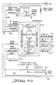
- numeral 10 designates transmission housing.
- Numeral 12 designates a hydrokinetic torque converter having an impeller 14, a bladed turbine 16 and a bladed stator 18, the latter being located between the flow entrance section of the impeller 14 and the flow exit section of the turbine 16.
- the impeller, the turbine and the stator are arranged in toroidal flow relationship in known fashion.
- the impeller forms a part of an impeller assembly that includes impeller shell 20 having a radial wall 22.
- a cavity within the impeller housing 20 is formed between the shroud 24 of the turbine and the end wall 22.
- a clutch plate and damper assembly 26 is disposed in that cavity.
- Assembly 26 is splined to turbine hub 28, which in turn is splined to turbine sleeve shaft 30 extending through the hub of stator 18 and the hub of impeller 14.
- the sleeve shaft arrangement defines also a central converter bypass clutch control pressure passage 42 which communicates through a radial port 44 in the turbine shaft 30 with clutch control chamber 46 formed between the clutch plate and damper assembly 26 and the adjacent wall 22 of the impeller housing 20.
- Control pressure passage 42 communicates with a bypass clutch control valve 44 which comprises a multiple land valve spool 46 and an aligned valve plunger 48.
- Valve spring 50 urges the plunger 48 and the multiple land valve spool 46 in a left hand direction. That spring force is opposed by a pressure force acting on the end of land 52 of multiple land valve spool 46. Pressure is distributed to the valve chamber on the left side of the land 52 through a bypass clutch solenoid pressure passage 54.
- a bypass clutch feed pressure passage 56 communicates with a control valve 44 at a location intermediate valve lands 58 and 60, the latter being smaller than the former so that a feedback pressure force opposes this force of the spring 50.
- Bypass clutch control pressure passage 42 communicates with the valve 44 at a location intermediate lands 58 and 60.
- Land 58 controls the degree of communication between passage 56 and exhaust port 62.
- a pulse width modulated solenoid actuator and valve assembly is shown at 64. Solenoid feed pressure is distributed to the actuator and valve assembly 64 through a feed passage 66.
- Solenoid feed pressure is distributed to the actuator and valve assembly 64 through a feed passage 66.
- the solenoid valve driver is powered by battery 68.
- An electronic microprocessor which will be described with reference to Figure 2, is shown in Figure 1 at 70.
- the processor 70 receives input signals from various sensors which measure engine and vehicle operating conditions.
- the output of the microprocessor is transferred through lead 72 to the bypass clutch pulse width modulated solenoid 64.
- the solenoid valve controlled by the pulse width modulated solenoid modulates the pressure in the solenoid feed pressure passage 66 and delivers a control signal through line 54 to the bypass clutch control valve.
- the clutch control valve is calibrated to receive the control pressure of the solenoid output to establish in line 42 and in control chamber 46 a pressure that will determine the controlled slip of the clutch.
- Figure 2 shows in schematic form the architecture of the processor 70 as well as the relationship of the processor to the hydraulic control valve body and to the transmission clutches and brakes.
- Figure 2 shows the schematic arrangement of the various sensors with respect to the processor and the hydraulic control valve body.
- the sensors convert physical signals to electrical signals.
- Physical signals include throttle position or engine manifold pressure, engine speed and transmission gear ratio selection as well as other variables such as engine temperature and the vehicle brake condition.
- the processor inputs these signals and operates on them according to a control program or a strategy and then outputs the results to certain actuators which function in cooperation with the hydraulic valve body to control the transmission.
- Processor 70 includes the central processing unit or CPU which comprises a computation unit and a control unit.
- An internal control bus establishes a relationship between a memory unit and the processing unit.
- Other internal busses establish a relationship between the CPU and the input conditioning signal circuit and the output driver circuit.
- the CPU executes programs that are fetched from memory and provide the timing and controlled values of the output signals to the hydraulic control valve body of the transmission.
- the input signal conditioning and the output driver system allow the microprocessor to read the input data from the microprocessor under the program control.
- the memory portion of the processor 70 stores programs and data and provides data to the processor as well as accepting new data from the processor for storage.
- the memory portion of the processor 70 of Figure 2 includes two types of memory; first, a read only memory or ROM which stores information or data that is read by the processor in each background loop and, second, a random access memory or RAM which holds or temporarily stores the results of the computations of the CPU as well as other data.
- the contents of the RAM can be erased, rewritten or changed depending upon the operating conditions of the vehicle.
- the two types of memory are stored in an integrated circuit in the form of a microprocessor chip whereas the computations performed by the CPU are the result of the function of a second integrated curcuit comprising a seperate microprocessor chip, the two chips being connected by an internal bus and interface circuitry.
- One of the input signals to the processor 70 is a throttle position signal in line 72 which is received by a position sensor 74.
- An engine speed sensor 76 in the form of a profile and condition pickup (PIP) delivers an engine speed signal through line 78 to the processor 70.
- An engine coolant sensor 80 delivers an engine temperature signal through line 82 to the processor 70.
- a barometric pressure sensor 84 delivers an altitude signal through line 86 to the processor 70.
- a vehicle speed sensor 90 measures or senses the speed of the driven element of the transmission 88 which is an indicator of the vehicle speed. That signal is delivered through line 92 to the processor 70.
- the drive range for the transmission is selected by the vehicle operator by manual adjustment of an adjustment lever schematically shown at 94.
- the various ranges are reverse, neutral, drive (D), direct drive ratio (3) and low speed ratio (1).
- Various shift patterns are established for the three forward drive ranges D, 3, and 1, depending upon the position that is selected by the vehicle operator. The position that is selected is sensed by the sensor and a position signal delivered through line 98 to the microprocessor 70.
- the microprocessor 70 includes also a sub-system identified as loss-of-signal-hardware (LOS). This hardware is adapted to establish an appropriate control signal for the output driver circuit that will cause the hydraulic valve body to continue operating with limited function in the event of an electronic voltage failure in the system.
- LOS loss-of-signal-hardware
- the electrohydraulic control valves are identified generally by reference character 100. They include a valve body 102 similar to that which is described in the aforesaid Timte and Van Selous patent disclosures.
- the output signals of the processor 70 are delivered to the control valve body through a plurality of leads as shown at 104 through 110.
- Lead 104 carries a converter bypass signal which communicates with the PWM solenoid 64, which communicates with valve 44, which leads to passage 42 and chamber 46 as seen in Figure 1.
- Lead 106 carries a control signal for a VFS throttle valve pressure control.
- Leads 108 and 110 carry shift solenoid pressure signals for effecting ratio changes in the transmission.
- the aforementioned Timte and Van Selous patent diclosures as well as the Bolz disclosure describe examples of the shift solenoids and the TV pressure control solenoid.
- the output signals of the electrohydraulic controls 100 are distributed to the transaxle 88 through control lines 116 through 126.
- Line 114 corresponds to control passage 42 shown in Figure 1. It extends to the converter bypass clutch control chamber.
- Lines 116, 118, 120, and 122 extend, respectively, to the forward clutch, the direct clutch, the intermediate clutch and the reverse clutch for the transaxle 88. These clutches can be seen by referring to the aforesaid Timte and Van Selous patents.
- Lines 124 and 126 extend, respectively, to the overdrive brake band and to the low and intermediate brake band for the transaxle 88. These bands can be seen by referring to the disclosure of the aforesaid Timte and Van Selous patents.
- the control system block diagram of Figure 3 illustrates the overall system that is used to establish a so called clutch engage mode.
- the different operating modes, including the engage mode, will be described subsequently with reference to Figures 7 and 8.
- control logic 71 is embodied in the control module or CPU of the processor 70.
- the various signals that are received by the processor 70 are illustrated and these correspond to those described with reference to Figure 2.
- the control logic 71 of the processor 70 calculates a desired slip, and that value is represented by a signal in line 128.
- the control software and electronics of Figure 3 are incorporated into the control system.
- the system is effective to establish in the bypass clutch sufficient capacity to hold the desired slip at the current torque. Torque transients then are absorbed by momentary periods of increased slip as the controller establishes a new output signal for the solenoid corresponding to the new torque condition.
- Numeral 130 designates the internal combustion engine
- numeral 132 designates an engine speed sensor which measures crankshaft speed.
- Transaxle or transmission 88 has a turbine speed sensor 134.
- the output signal of the sensor 134 is distributed through control lead 136 and through input sampling switch 138 to the control logic 71 of the processor 70.
- the turbine speed signal is distributed also to a comparator circuit 140.
- Engine speed measured by the sensor 132 is distributed through control line 142 and through input sampling switch 144 to the control logic of processor 70. That signal is distributed also the summing point 140.
- the comparator at the summing point 140 determines whether there is any difference between the turbine speed and the engine speed. This value is called an actual slip, and the value of that actual slip is represented by a signal in lead 146, which is distributed to summing point 148. The difference between the value of the signal in lead 146 and the desired slip signal in lead 128 is measured by the comparator or summing point 148 to establish a slip error signal in line 150.
- This error signal is distributed to a proportional-integral-derivative controller (PID controller) shown at 152.
- PID controller proportional-integral-derivative controller
- This controller may be of a well known variety. It is inserted into the control loop to form a part of the forward gain of the control system. It effects proportional control, an integral control and a differential control. By adjusting the magnitude of these terms, the actual signal that is the output of the PID controller can be modified so as to produce the required system response.
- the proportional control feature of the PID controller makes it possible for the output of the controller to be varied directly with the slip error. It produces a so called gain factor, which is a measure of the control gain in the system that reduces accordingly the magnitude of any steady state errors. Because the proportional control by itself, of necessity, establishes a gain factor of limited range, it is not sufficient to achieve the desired response due to steady state errors or undesired slip oscillations.
- the integral control component of the PID controller eliminates steady state error for improved system accuracy. The response can further be improved to effect system stability and effective transient response of the system by introducing the derivative control. This introduces a stablizing effect on the system because of the addition of phase lead to the control loop.
- the output of the PID controller is a duty cycle signal distributed through line 154. This is received by a peak-and-hold driver curcuit 156 for the pulse width modulated solenoid 158, the latter being connected to the driver circuit 156 through line 104.
- VFS variable force solenoid
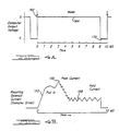
- the peak-and-hold circuit for the PWM solenoid may be of a conventional type. It is effective to establish at the input side of the solenoid a driver voltage similar to that shown in Figure 4B upon receipt of a signal from the PID controller. As shown in Figure 4A at 160, the peak-and-hold circuit establishes a change in the solenoid input represented by the steep slope portion 162 of the curve in Figure 4B. During the initial part of the hold time during which the controller output voltage is established at a value shown at 164, a peak current is established by the driver as shown at 166. This overcomes the initial friction and inertia of the solenoid (pull-in). That event is followed by a moderate hold current value as shown at 168 until the termination of the duty cycle on-time at 170. The cycle is repeated again in the next duty cycle period.
- the output of the solenoid valve 158 which would correspond to the solenoid valve 64 of Figure 1, is distributed to the bypass clutch control valve 44 described with reference to Figure 1.
- the output of the bypass clutch control valve is a pressure signal in passage 42 which, as explained with reference to Figure 1, communicates with control pressure chamber 46 for the converter bypass clutch 26.
- the background control loop would include various stages, only one of which would include the stages illustrated in Figure 5.
- the sequence would exit from the main control loop and perform the control stages of Figure 5 in a sub-routine. For example, following initialization of the controller, the inputs are read from the various engine and vehicle condition sensors. In a subsequent stage the various system equations and data stored in memory are used to establish various control funtions for the engine and transmission including the setting of the idle speed, the setting of the rate of fuel delivery by the engine injection system, the setting of the spark advance, and so forth. Following those stages the sequence of operations shown schematically in the flow diagram of Figure 5 would take place.
- the controller will read and process the input signals from the various sensors that control the transmission. This occurs at stage 174. Those sensor inputs are the engine speed, the input shaft speed or turbine shaft speed, vehicle speed and throttle position as well as the gear shift selector lever position, oil temperature and the brake on-off condition. Based on that sensor information the operating conditions for the torque converter are calculated to determine the actual converter slip speed and the converter speed ratio. The actual converter slip speed is equal to engine RPM minus turbine shaft RPM and the converter speed ratio is equal to turbine shaft speed divided by engine speed. These calculations occur at stage 176.
- the controller determines the required bypass clutch operation mode based on the operating conditions that are determined at stage 176. This occurs at stage 178 in Figure 5.
- the operating modes for the clutch are the unlock mode, the stroke mode and the engage mode. If the unlock mode is called for, an open converter condition is in effect and the calculation of a desired slip is not applicable. The same is true for the stroke mode, which occurs at an instant prior to the engage mode following operation of the converter as an open converter. Again desired slip is not applicable.
- the bypass clutch loop is closed and desired slip is calculated based upon actual converter slip and a final target value for the slip. This will be described subsequently.
- bypass clutch operating mode is best described with reference to Figure 7. If the operating conditions indicate that the bypass clutch should operate in the unlock mode indicated at stage 180 in Figure 7, then an inquiry is made by the controller to determine whether the vehicle speed is greater than five miles per hour and if the transmission selector is in the drive range or the overdrive range. This inquiry occurs at stage 182. If the answer to that inquiry is negative, the procedure does not advance and the flag that would cause a jump from stage 182 to a subsequent stage does not change. The operating sequence then would cause the controller to remain in the unlock mode stage 180 and continue inquiry 182. If the answer to inquiry 182 is positive, the unlock flag is cleared and the stroke mode flag is set thus advancing the sequence to stage 184.
- stage number 186 an inquiry is made at stage number 186 with respect to whether the speed of the vehicle is less than five mile per hour or if the selector lever chosen by the operator is in the drive or the overdrive position. If the answer to that inquiry is positive, the unlock flag is set and the stroke mode flag is cleared. Thus the sequence returns again to the unlock mode stage 180. On the other hand if the inquiry at stage 186 is negative, the flags do not change, and the sequence advances to stage 188 where a further inquiry is made with respect to whether the throttle position is greater than 4% open, whether the vehicle is not downshifting and whether the converter speed ratio is greater than a predetermined throttle function.
- stage 192 Upon reaching the engage mode stage at 190 a further inquiry is made at stage 192 with respect to whether the transmission is downshifting or if the throttle position is less than 2% open. If the answer to that inquiry is positive, the stroke mode flag is set and the engage mode flag is cleared. The subroutine then returns to the stroke mode. That subroutine is repeated for each background loop until the operating conditions permit a negative answer to the inquiry at 192. If that is the case the flags for the stroke and engage modes do not change and the sequence proceeds to stage 194 where a further inquiry is made with respect to whether the speed of the vehicle is less than five miles per hour, and whether the operator has positoned the selector lever in the drive range or the overdrive range.
- the unlock flag is set and the sequence returns to the beginning stage at 180. Likewise the engage mode flag is cleared. On the other hand if the inquiry at stage 194 is negative, the flags do not change and the sequence remains in the engage mode at 190 and proceeds, during each background pass, to repeat the two inquiries at 192 and 194 until the result of the inquiry at 194 becomes positive and the unlock flag becomes set.
- Figure 7A is a block diagram that shows the sequence described in the foregoing description of the bypass clutch operating modes.
- the transition paths from one mode to another have been labelled by the symbols A, B, C, D, and E.
- the corresponding points on the flowchart of Figure 7 are identified by identical reference labels so the block diagram of Figure 7A can be correlated to the flow chart of Figure 7.
- Figure 7A shows the three clutch operating modes; i.e., the unlock mode, the stroke mode and the engage mode. It is possible for a transition to occur from the unlock mode only to the stroke mode along path A.
- the control sequence having reached the stroke mode stage it is possible for either of two events to occur. In the first place, the sequence can return to the unlock mode along path B; or if conditions permit, the engage mode can be entered along path C.
- the sequence having entered the engage mode again either one of two events can occur.
- the engage mode can be terminated and the stroke mode reinstituted along the transition path D.
- an unlock mode is called, a transition is made from the engage mode to the unlock mode along transition path E to the unlock mode.
- the calculation that occurs at stage 196 makes use of information that is stored in the processor memory registers. These registers, for each background loop, have stored in them an actual slip value which is equal to the actual converter slip measured as previously described. It has stored in it also an absolute converter slip, which is an absolute value of the actual converter slip.
- the controller when the sequence is in the engage mode, determines a so called desired slip and stores that value in memory where it can be fetched for a determination subsequently of the bypass clutch solenoid duty cycle.
- the desired slip is equal to the actual slip, measured as previously described, minus a percentage of the difference between the actual slip and the target slip.
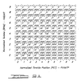
- FIG. 9 shows a table of data, charted in Figure 9, in a two dimensional plot. For each normalized throttle position on the horizontal axis and for each normalized turbine speed value on the vertical axis, a target slip value may be read or interpolated.
- Figure 8 shows the control stategy in flow chart form for determining desired slip, as will be explained below.
- the first step includes setting the absolute slip equal to the absolute value for converter slip.
- Curve 196 is a plot showing the actual slip versus time and plot 198 shows the desired slip versus time.
- Plot 198 is a result of the calculation described above using the three error values described previously; i.e., the error (E0) currently measured by the slip controller, the error (E1) determined in the previous background loop and the error (E2) determined in the second previous background loop. These error values also are indicated in Figure 6.
- the target slip is indicated by the symbol T.
- the value of that target slip will be determined by the throttle angle and turbine speed that exist for any particular gear ratio. As mentioned previously that information is obtained from table 9A.
- the desired slip is calculated for each background loop so that the value of the absolute slip approaches asymptotically the value of the target slip.
- Figure 6A shows the same information as Figure 6, although the information is illustrated in graphic form where the line A represents absolute slip and the line D represents the value of desired slip for successivelysive background loops. As seen from Figures 6A, the value of A approaches the target slip value as the background loops are repeated.
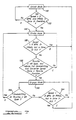
- the procedure used to establish desired slip is graphically illustrated in the flow chart in Figure 8.
- the routine begins at stage 200.
- stage 202 the value of the absolute slip is determined based upon the actual slip value.
- the procedure proceeds to stage 204 where an inquiry is made with respect to the gear ratio that is determined by the gear ratio sensor. If the gear ratio is greater than the third ratio, the sequence proceeds to stage 206. If the ratio is the fourth ratio at that time the appropriate stored value of the target slip in Figures 9 or 9A is read from memory. On the other hand if the gear ratio is that corresponding to third gear, another target value is read at stage 208. That occurs if the inquiry at stage 204 is negative. In either case the routine will proceed to stage 210, where an inquiry is made with respect to the gear ratio in place.
- the slip reduction factor PCDEC4 is stored in the temporary storage register as shown at stage 212. If the inquiry at stage 210 is negative, the routine proceeds to stage 214 where another inquiry is made to determine whether the gear ratio is that corresonding to third gear. If the answer to that inquiry is positive, slip reduction factor PCDEC3 corresponding to that gear ratio is fetched from memory and stored in the temporary storage register as shown at stage 216. If the inquiry at stage 214 is negative, the routine proceeds to stage 218 where a determination is made as to whether the gear ratio is that corresponding to second gear. If the answer to that inquiry is positive, a temporary holding register receives still another slip reduction factor PCDEC3 from memory. That stage is indicated at 220. If the inquiry at 218 is negative, the routine proceeds to stage 222 which causes the temporary holding register to receive a new data item (PCDEC1) from memory.
- PCDEC1 new data item
- the routine then passes to the final stage 224 where a desired slip calculation takes place using the temporary register data in the formula previously described.
- desired slip is equal to the absolute slip minus a percent of the difference of the absolute slip and the target slip for the particular background loop in place.
- the previous error E2 is set equal to E1 and the previous error E1 is set equal to E2 as the error E0 is set equal to the absolute slip minus the desired slip. This updates the information for each background loop so that a new error can be calculated for the next loop.
- the duty cycle is zero. If the system is in the stroke mode, the duty cycle is adjusted as a function of the throttle position to provide a sufficient hydraulic pressure such that the clutch will continue to be disengaged, but such that any additional pressure will cause the clutch to engage. Thus the clutch is maintained at a so-called incipient engaged (stroked) position.
- E0 is the current error
- E1 is the previous error
- E2 is the second previous error
- T0 is the time of the present control loop between the current and previous error readings.
- T1 is the time interval between the previous and the second previous error readings.
- T2 is the time interval between two successive earlier error readings.
- K p is a proportional gain constant
- K d is a derivative gain constant
- K i is the integral gain constant.
- the output change equals the output-new formula minus the output-old formula. That value is computed in accordance with the following formula:
- Output-change formula K p (E0-E1) + K d [(E0-E1)/T0 + (E2-E1)/T1] + K i *E0*T0
- the converter slip is calculated using engine RPM and transmission input speed or turbine speed. That slip is compared to the desired slip. In order to determine the error signal, the controller routine then adjusts the solenoid duty cycle to minimize the slip error in accordance with the chart of Figure 6.
- Control strategy is broken down into two basic parts. At the outset there is a determination of the operating mode.
- the mode that is selected is one of three modes; i.e., the unlock mode, the stroke mode and the engage mode.
- the unlock mode is called for when the gear selector lever is not in the drive or overdrive position, or when the vehicle is not moving at a speed greater than the minimum value such as five miles per hour, or the throttle position is at a wide open setting, or the transmission oil temperature is low or the brake is applied.
- the stroke mode is allowed when the unlock mode is not required and the conditions to engage are not met.
- the stroke mode is not allowed when the transmission is downshifting or when the throttle opening falls below a throttle position versus vehicle speed function that is predetermined. That function prevents engagement during coast conditions.
- the engage mode is allowed when the unlock or stroke modes are not required and the converter speed ratio is confirmed to be operating above a speed ratio versus throttle position function that is predetermined. That function is established at a value that will prevent the bypass clutch engagement from adversly effecting vehicle performance.
- the pulse width modulated solenoid duty cycle is determined by throttle position using a duty cycle versus throttle position function. This function is calibrated to provide stroke pressure to the bypass clutch. Stroke pressure is that amount which does not reduce slip, but the value is slightly below the value at which slip would begin to be reduced.
- the stroke mode is used to prepare for a smooth transition into the engage mode and into the closed loop control.
- the engage mode uses a PID controller to minimize slip error.
- the controller determines error by comparing the actual slip to desired slip. Rapid torque changes will result in eventual compensation of duty cycle, but will allow rapid torque changes to be absorbed by short periods of increased slip, or decreased slip, as the case may be, without being felt by the driver.
- the value for the desired slip is determined based upon the actual slip and a final target value and subtracting from the actual slip a percentage of the difference between the actual slip and the first target slip.
- the percentage factor in the formula determines how quickly the final slip target is attained. It may vary depending upon the transmission gear.
- the values for target slip are calibrated and are stored in memory for access by the controller during the engage mode.
- the final target slip is in the form of slip tables of throttle position versus turbine speed. These values, which are addressable, are calibrated to avoid pulling the engine speed below its lugging limit and to provide enough slip to absorb engine RPM fluctuations not isolated by the converter damper
- the input to the solenoid driver circuit is the output of a PID controller, which uses the logic of the engage mode routine. It uses the current slip error, the previous slip error and the error of two previous loops to determine the required change in the duty cycle for each background loop of the controller.
Applications Claiming Priority (2)
| Application Number | Priority Date | Filing Date | Title |
|---|---|---|---|
| US383506 | 1989-07-24 | ||
| US07/383,506 US5029087A (en) | 1989-07-24 | 1989-07-24 | Electronic control system for controlling torque converter bypass clutches |
Publications (3)
| Publication Number | Publication Date |
|---|---|
| EP0410223A2 true EP0410223A2 (de) | 1991-01-30 |
| EP0410223A3 EP0410223A3 (en) | 1991-09-25 |
| EP0410223B1 EP0410223B1 (de) | 1995-06-21 |
Family
ID=23513477
Family Applications (1)
| Application Number | Title | Priority Date | Filing Date |
|---|---|---|---|
| EP90113377A Expired - Lifetime EP0410223B1 (de) | 1989-07-24 | 1990-07-12 | Elektronisches Steuerungssystem zur Kontrolle einer Überbrückungskupplung eines Momentwandlers |
Country Status (4)
| Country | Link |
|---|---|
| US (1) | US5029087A (de) |
| EP (1) | EP0410223B1 (de) |
| JP (1) | JPH0366977A (de) |
| DE (1) | DE69020252T2 (de) |
Cited By (14)
| Publication number | Priority date | Publication date | Assignee | Title |
|---|---|---|---|---|
| EP0533419A1 (de) * | 1991-09-14 | 1993-03-24 | Honda Giken Kogyo Kabushiki Kaisha | Überbrückungskupplungssteuerung für ein automatisches Kraftfahrzeuggetriebe |
| EP0571275A1 (de) * | 1992-05-19 | 1993-11-24 | Regie Nationale Des Usines Renault S.A. | Steuervorrichtung für ein automatisches Stufengetriebe |
| FR2701301A1 (fr) * | 1993-02-05 | 1994-08-12 | Renault | Convertisseur de couple hydrocinétique pontable à réacteur bloqué. |
| FR2710123A1 (fr) * | 1993-09-17 | 1995-03-24 | Luk Getriebe Systeme Gmbh | Véhicule avec convertisseur hydrodynamique de couple associé à un embrayage de pontage et procédé de commande de ce dernier. |
| EP0699852A1 (de) * | 1994-09-02 | 1996-03-06 | General Motors Corporation | Steuerung für eine Drehmomentwandler-Überbrückungskupplung mit einstellbarem Übertragungsvermögen |
| EP0692657A3 (de) * | 1994-07-13 | 1996-05-15 | Toyota Motor Co Ltd | Anordnung zur Regelung des Schlupfs einer Überbrückungskupplung eines Kraftfahrzeuges |
| GB2302145A (en) * | 1992-08-21 | 1997-01-08 | Luk Getriebe Systeme Gmbh | Torque transmission arrangement having a lockup clutch and a torque converter with a conversion of greater than 2.5 |
| EP0754890A2 (de) * | 1995-07-17 | 1997-01-22 | Toyota Jidosha Kabushiki Kaisha | System zur Regelung des Schlupfes einer Ueberbrückungskupplung |
| FR2743128A1 (fr) * | 1995-12-30 | 1997-07-04 | Bosch Gmbh Robert | Systeme de surveillance d'un embrayage |
| GB2320535A (en) * | 1994-02-23 | 1998-06-24 | Luk Getriebe Systeme Gmbh | Method for controlling a lock-up clutch |
| EP1357315A2 (de) * | 2002-04-25 | 2003-10-29 | JATCO Ltd | Steuerungssystem für die Überbrückungskupplung eines automatischen Getriebes |
| EP2085660A1 (de) * | 2008-02-01 | 2009-08-05 | GM Global Technology Operations, Inc. | Verfahren zur Kalibrierung eines Automatikgetriebes |
| CN103307271A (zh) * | 2012-03-05 | 2013-09-18 | 通用汽车环球科技运作有限责任公司 | 动力接通升档期间用pid控制逻辑确定变速器离合器控制值 |
| CN105276030A (zh) * | 2014-07-16 | 2016-01-27 | 福特全球技术公司 | 控制具有泵轮离合器的传动装置的方法 |
Families Citing this family (62)
| Publication number | Priority date | Publication date | Assignee | Title |
|---|---|---|---|---|
| DE58901710D1 (de) * | 1988-07-30 | 1992-07-23 | Zahnradfabrik Friedrichshafen | Verfahren und einrichtung zur steuerung einer kupplung. |
| US5121820A (en) * | 1990-12-24 | 1992-06-16 | Ford Motor Company | Feedforward control for automatic transmission torque converter bypass clutch slip |
| US5179875A (en) * | 1991-03-22 | 1993-01-19 | Ford Motor Company | Turbine speed controller for an automatic transmission |
| DE4124603A1 (de) * | 1991-07-25 | 1993-01-28 | Porsche Ag | Verfahren zur steuerung des betaetigungsdrucks in einem stellglied eines elektrohydraulisch gesteuerten kraftfahrzeuggetriebes |
| EP0529138B1 (de) * | 1991-08-30 | 1995-10-25 | Siemens Aktiengesellschaft | Steuerung für einen Kraftfahrzeugantrieb mit einem automatischen Getriebe |
| JPH05133469A (ja) * | 1991-11-11 | 1993-05-28 | Japan Electron Control Syst Co Ltd | 車両用自動変速機の制御装置 |
| US5305663A (en) * | 1992-08-10 | 1994-04-26 | Ford Motor Company | Automatic transmission control system |
| US5303616A (en) * | 1992-08-10 | 1994-04-19 | Ford Motor Company | Electronically controlled bypass clutch based on percent-shift-completion for a torque converter |
| US5315901A (en) * | 1992-12-17 | 1994-05-31 | Ford Motor Company | Automatic transmission with a modulated pressure converter bypass clutch priority valve circuit |
| US5514047A (en) * | 1993-03-08 | 1996-05-07 | Ford Motor Company | Continuously variable transmission |
| JP3422519B2 (ja) * | 1993-05-14 | 2003-06-30 | ジヤトコ株式会社 | 自動変速機のロックアップ制御装置 |
| US5383825A (en) * | 1993-05-25 | 1995-01-24 | Ford Motor Company | Electronic shift controller for a multiple ratio automotive transmission |
| US5389046A (en) * | 1993-05-25 | 1995-02-14 | Ford Motor Company | Automatic transmission control system |
| US5415606A (en) * | 1993-07-06 | 1995-05-16 | Ford Motor Company | Synchronous shift coordination responsive to an O/D switch in an automatic transmission |
| US5475590A (en) * | 1993-10-22 | 1995-12-12 | Ford Motor Company | Automatic transmission torque converter bypass clutch control using engine torque compensation |
| DE19504847B4 (de) * | 1994-02-23 | 2006-04-27 | Luk Gs Verwaltungs Kg | Überwachungsverfahren für ein Drehmoment-Übertragungssystem eines Kraftfahrzeugs |
| US7286922B1 (en) * | 1994-02-23 | 2007-10-23 | Luk Getriebe-Systeme Gmbh | Method of and apparatus for transmitting torque in vehicular power trains |
| US5626536A (en) * | 1994-07-19 | 1997-05-06 | Toyota Jidosha Kabushiki Kaisha | Lock-up clutch slip control apparatus and engine fuel-cut control apparatus for motor vehicle |
| JP3211630B2 (ja) * | 1994-07-20 | 2001-09-25 | トヨタ自動車株式会社 | 車両用ロックアップクラッチのスリップ制御装置 |
| US5722519A (en) * | 1994-10-14 | 1998-03-03 | Ford Global Technologies, Inc. | Multiple ratio automatic transmission and torque converter |
| US5553694A (en) | 1994-10-14 | 1996-09-10 | Ford Motor Company | Multiple ratio automatic transmission and torque converter |
| US5612874A (en) | 1994-10-14 | 1997-03-18 | Ford Motor Company | Multiple ratio automatic transmission with solenoid operated valves for effecting pressure buildup |
| US5646842A (en) * | 1994-10-14 | 1997-07-08 | Ford Motor Company | Shift control system for a multiple ratio automatic transmission |
| US5586029A (en) * | 1994-10-14 | 1996-12-17 | Ford Motor Company | Shift control system for a multiple ratio automatic transmission with manual ratio ranges |
| JPH08121592A (ja) * | 1994-10-27 | 1996-05-14 | Fuji Heavy Ind Ltd | 自動変速機のロックアップ制御装置 |
| JP2928734B2 (ja) * | 1994-10-31 | 1999-08-03 | 本田技研工業株式会社 | 車両用クラッチ機構の作動状態判定装置 |
| US5527238A (en) * | 1995-04-10 | 1996-06-18 | Ford Motor Company | Automatic transmission bypass clutch slip control using nonlinear nverse dynamics |
| JP3637631B2 (ja) * | 1995-05-12 | 2005-04-13 | マツダ株式会社 | 自動変速機の故障判定装置及び故障判定方法 |
| DE19548564A1 (de) * | 1995-12-23 | 1997-06-26 | Bosch Gmbh Robert | Verfahren und Vorrichtung zur Antriebsschlupfregelung |
| US5802490A (en) | 1996-02-20 | 1998-09-01 | Ford Global Technologies, Inc. | Torque converter regulator and clutch lockout system for an automotive vehicle |
| US5637053A (en) | 1996-02-20 | 1997-06-10 | Ford Motor Company | Torque converter clutch lockout hydraulic system |
| US5799260A (en) | 1996-02-20 | 1998-08-25 | Ford Global Technologies, Inc. | System for controlling multiple hydraulic pumps in an automatic transmission |
| US5700226A (en) | 1996-02-20 | 1997-12-23 | Ford Global Technologies, Inc. | Hydraulic lubrication control system for an automatic transmission |
| US5762134A (en) * | 1996-02-20 | 1998-06-09 | Ford Global Technologies, Inc. | Hydraulic temperature compensated cooler bypass control for an automatic transmission |
| US5740083A (en) * | 1996-04-01 | 1998-04-14 | Ford Motor Company | Delta time measurement circuit for determining parameter derivatives of a rotational velocity sensor signal |
| US5835876A (en) * | 1996-08-20 | 1998-11-10 | Ford Global Technologies, Inc. | Torque converter clutch solenoid functional test |
| JP3240939B2 (ja) * | 1996-11-07 | 2001-12-25 | 日産自動車株式会社 | トルクコンバータのロックアップ制御装置 |
| US5890509A (en) * | 1997-03-31 | 1999-04-06 | Ford Global Technologies, Inc. | Hydraulic temperature compensated cooler bypass control for an automatic transmission |
| JP3240979B2 (ja) * | 1997-11-04 | 2001-12-25 | 日産自動車株式会社 | トルクコンバータのスリップ制御装置 |
| DE19826059B4 (de) * | 1998-06-12 | 2006-04-06 | Zf Friedrichshafen Ag | Verfahren zum Steuern eines Automatgetriebes |
| DE19963236B4 (de) | 1999-01-12 | 2016-01-28 | Schaeffler Technologies AG & Co. KG | Hydrodynamischer Drehmomentwandler |
| US6434466B1 (en) * | 1999-05-06 | 2002-08-13 | Ford Global Technologies, Inc. | System and method for determining engine torque for controlling a powertrain |
| US6253140B1 (en) | 1999-08-04 | 2001-06-26 | Ford Global Technologies, Inc. | Engagement control logic for an automatic transmission clutch with adaptive engagement feel |
| US6449548B1 (en) * | 2001-02-14 | 2002-09-10 | Ford Global Technologies, Inc. | Automatic transmission shift control |
| JP4516917B2 (ja) * | 2003-10-24 | 2010-08-04 | 株式会社小松製作所 | エンジン動力伝達装置及びその方法 |
| US6980898B2 (en) * | 2003-12-19 | 2005-12-27 | Daimlerchrysler Corporation | Downshift acceleration control |
| JP2007113735A (ja) * | 2005-10-21 | 2007-05-10 | Toyota Motor Corp | 摩擦係合要素の制御装置 |
| US7693635B2 (en) * | 2006-03-22 | 2010-04-06 | Gm Global Technology Operations, Inc. | Method for learning the flow rate of hydraulic fluid in an automatic transmission |
| DE102008025528A1 (de) | 2007-06-14 | 2008-12-18 | Luk Lamellen Und Kupplungsbau Beteiligungs Kg | Verwendung einer Drehmomentwandlerpumpenkupplung um Schwingungsstöße in einem Fahrzeuggetriebe zu beseitigen |
| US8052575B2 (en) * | 2008-03-19 | 2011-11-08 | GM Global Technology Operations LLC | Active fuel management mode torque converter clutch control |
| JP4630355B2 (ja) * | 2008-06-19 | 2011-02-09 | ジヤトコ株式会社 | 自動変速機の変速制御装置 |
| US8666618B2 (en) * | 2008-10-31 | 2014-03-04 | Caterpillar Inc. | Machine control system implementing application-based clutch modulation |
| US8142329B2 (en) * | 2009-09-18 | 2012-03-27 | Ford Global Technologies, Llc | Controlling torque in a flywheel powertrain |
| JP5031052B2 (ja) * | 2010-03-16 | 2012-09-19 | ジヤトコ株式会社 | 自動変速機の制御装置 |
| US8546176B2 (en) | 2010-04-22 | 2013-10-01 | Tsmc Solid State Lighting Ltd. | Forming chalcogenide semiconductor absorbers |
| JP5605078B2 (ja) * | 2010-08-20 | 2014-10-15 | マツダ株式会社 | トルクコンバータ |
| US9242630B2 (en) * | 2014-01-28 | 2016-01-26 | GM Global Technology Operations LLC | Method and apparatus for controlling a torque converter clutch in a multi-mode powertrain system |
| US9670972B2 (en) | 2014-04-28 | 2017-06-06 | Twin Disc, Inc. | Trimmed lock-up clutch |
| US9771079B2 (en) * | 2016-01-11 | 2017-09-26 | Cnh Industrial America Llc | Systems and method for control of a power take-off clutch |
| CN110984282B (zh) * | 2019-12-20 | 2021-08-24 | 徐州徐工挖掘机械有限公司 | 一种基于发动机最大可用扭矩的挖掘机控制方法 |
| CN113064443B (zh) * | 2021-03-08 | 2022-10-11 | 北京理工大学 | 增益在线调整方法及使用其的阻尼回路控制方法 |
| US11679758B1 (en) * | 2021-12-10 | 2023-06-20 | Ford Global Technologies, Llc | Dynamic adaption methods and system for a driveline disconnect clutch |
Citations (5)
| Publication number | Priority date | Publication date | Assignee | Title |
|---|---|---|---|---|
| US4428467A (en) * | 1981-03-31 | 1984-01-31 | Mitsubishi Jidosha Kogyo Kabushiki Kaisha | Friction clutch control device |
| GB2163230A (en) * | 1984-08-17 | 1986-02-19 | Mitsubishi Motors Corp | Controlling clutch slip particularly in torque converter lock up clutches |
| EP0240282A2 (de) * | 1986-03-31 | 1987-10-07 | Fuji Jukogyo Kabushiki Kaisha | Steuervorrichtung für den Öldruck eines stufenlos regelbaren Getriebes |
| EP0275463A2 (de) * | 1987-01-20 | 1988-07-27 | Ford-Werke Aktiengesellschaft | Rutschregelung für eine Getriebekupplung |
| EP0310117A1 (de) * | 1987-10-01 | 1989-04-05 | Mazda Motor Corporation | Überbrückungssteuersysteme für ein automatisches Getriebe |
Family Cites Families (12)
| Publication number | Priority date | Publication date | Assignee | Title |
|---|---|---|---|---|
| US3252352A (en) * | 1963-02-18 | 1966-05-24 | Ford Motor Co | Hydrokinetic power transmitting mechanism |
| US3497043A (en) * | 1968-07-25 | 1970-02-24 | Ford Motor Co | Multiple ratio gearing for an automotive vehicle driveline |
| US4090417A (en) * | 1976-01-07 | 1978-05-23 | Ford Motor Company | Control system for an automatic transmission with a hydrokinetic torque converter and an integral lockup clutch |
| US4468988A (en) * | 1980-08-04 | 1984-09-04 | Mitsubishi Jidosha Kogyo Kabushiki Kaisha | Slip control system for a clutch |
| US4487303A (en) * | 1982-12-27 | 1984-12-11 | Ford Motor Company | Automatic transmission start-up clutch control system |
| US4725951A (en) * | 1983-12-29 | 1988-02-16 | Nissan Motor Co., Ltd. | Control system for lock-up clutch in torque converter |
| JPH0721313B2 (ja) * | 1985-06-11 | 1995-03-08 | 三菱自動車工業株式会社 | 流体継手用クラッチの制御装置 |
| JPS62103236A (ja) * | 1985-10-30 | 1987-05-13 | Diesel Kiki Co Ltd | クラッチ制御装置 |
| JPS62297567A (ja) * | 1986-06-16 | 1987-12-24 | Honda Motor Co Ltd | 車両用変速機における流体トルクコンバ−タ用クラツチの作動制御方法 |
| JP2702703B2 (ja) * | 1986-06-30 | 1998-01-26 | アイシン・エィ・ダブリュ株式会社 | ロツクアツプクラツチ付自動変速機 |
| US4724939A (en) * | 1986-07-17 | 1988-02-16 | General Motors Corporation | Closed loop clutch slip control system with turbine roughness control |
| US4875391A (en) * | 1988-04-29 | 1989-10-24 | Chrysler Motors Corporation | Electronically-controlled, adaptive automatic transmission system |
-
1989
- 1989-07-24 US US07/383,506 patent/US5029087A/en not_active Expired - Lifetime
-
1990
- 1990-07-12 EP EP90113377A patent/EP0410223B1/de not_active Expired - Lifetime
- 1990-07-12 DE DE69020252T patent/DE69020252T2/de not_active Expired - Lifetime
- 1990-07-23 JP JP2194703A patent/JPH0366977A/ja active Pending
Patent Citations (5)
| Publication number | Priority date | Publication date | Assignee | Title |
|---|---|---|---|---|
| US4428467A (en) * | 1981-03-31 | 1984-01-31 | Mitsubishi Jidosha Kogyo Kabushiki Kaisha | Friction clutch control device |
| GB2163230A (en) * | 1984-08-17 | 1986-02-19 | Mitsubishi Motors Corp | Controlling clutch slip particularly in torque converter lock up clutches |
| EP0240282A2 (de) * | 1986-03-31 | 1987-10-07 | Fuji Jukogyo Kabushiki Kaisha | Steuervorrichtung für den Öldruck eines stufenlos regelbaren Getriebes |
| EP0275463A2 (de) * | 1987-01-20 | 1988-07-27 | Ford-Werke Aktiengesellschaft | Rutschregelung für eine Getriebekupplung |
| EP0310117A1 (de) * | 1987-10-01 | 1989-04-05 | Mazda Motor Corporation | Überbrückungssteuersysteme für ein automatisches Getriebe |
Cited By (30)
| Publication number | Priority date | Publication date | Assignee | Title |
|---|---|---|---|---|
| US5267158A (en) * | 1991-09-14 | 1993-11-30 | Honda Giken Kogyo Kabushiki Kaisha | Lock-up clutch fuzzy logic control system of vehicle automatic transmission |
| EP0533419A1 (de) * | 1991-09-14 | 1993-03-24 | Honda Giken Kogyo Kabushiki Kaisha | Überbrückungskupplungssteuerung für ein automatisches Kraftfahrzeuggetriebe |
| EP0571275A1 (de) * | 1992-05-19 | 1993-11-24 | Regie Nationale Des Usines Renault S.A. | Steuervorrichtung für ein automatisches Stufengetriebe |
| FR2691516A1 (fr) * | 1992-05-19 | 1993-11-26 | Renault | Dispositif de contrôle de transmission automatique à rapports étagés. |
| US5409426A (en) * | 1992-05-19 | 1995-04-25 | Regie Nationale Des Usines Renault S.A. | Automatic transmission control device with stepped gears |
| GB2302145B (en) * | 1992-08-21 | 1997-04-30 | Luk Getriebe Systeme Gmbh | Torque transmission arrangement |
| GB2302145A (en) * | 1992-08-21 | 1997-01-08 | Luk Getriebe Systeme Gmbh | Torque transmission arrangement having a lockup clutch and a torque converter with a conversion of greater than 2.5 |
| FR2701301A1 (fr) * | 1993-02-05 | 1994-08-12 | Renault | Convertisseur de couple hydrocinétique pontable à réacteur bloqué. |
| FR2710123A1 (fr) * | 1993-09-17 | 1995-03-24 | Luk Getriebe Systeme Gmbh | Véhicule avec convertisseur hydrodynamique de couple associé à un embrayage de pontage et procédé de commande de ce dernier. |
| GB2320535B (en) * | 1994-02-23 | 1998-08-26 | Luk Getriebe Systeme Gmbh | Method for controlling a lock-up clutch |
| GB2320535A (en) * | 1994-02-23 | 1998-06-24 | Luk Getriebe Systeme Gmbh | Method for controlling a lock-up clutch |
| US5803868A (en) * | 1994-07-13 | 1998-09-08 | Toyota Jidosha Kabushiki Kaisha | Slip control apparatus for motor vehicle lock-up clutch |
| EP0692657A3 (de) * | 1994-07-13 | 1996-05-15 | Toyota Motor Co Ltd | Anordnung zur Regelung des Schlupfs einer Überbrückungskupplung eines Kraftfahrzeuges |
| EP0787933A2 (de) * | 1994-07-13 | 1997-08-06 | Toyota Jidosha Kabushiki Kaisha | Schlupfregelanordnung einer Überbrückungskupplung eines Kraftfahrzeuges |
| EP0787932A2 (de) * | 1994-07-13 | 1997-08-06 | Toyota Jidosha Kabushiki Kaisha | Anordnung zur Regelung des Schlupfs einer Überbrückungskupplung eines Kraftfahrzeugs |
| US5683329A (en) * | 1994-07-13 | 1997-11-04 | Toyota Jidosha Kabushiki Kaisha | Slip control apparatus for motor vehicle lock-up clutch |
| EP0787933A3 (de) * | 1994-07-13 | 1998-01-14 | Toyota Jidosha Kabushiki Kaisha | Schlupfregelanordnung einer Überbrückungskupplung eines Kraftfahrzeuges |
| EP0787932A3 (de) * | 1994-07-13 | 1998-01-14 | Toyota Jidosha Kabushiki Kaisha | Anordnung zur Regelung des Schlupfs einer Überbrückungskupplung eines Kraftfahrzeugs |
| EP0699852A1 (de) * | 1994-09-02 | 1996-03-06 | General Motors Corporation | Steuerung für eine Drehmomentwandler-Überbrückungskupplung mit einstellbarem Übertragungsvermögen |
| EP0754890A3 (de) * | 1995-07-17 | 1998-04-01 | Toyota Jidosha Kabushiki Kaisha | System zur Regelung des Schlupfes einer Ueberbrückungskupplung |
| EP0754890A2 (de) * | 1995-07-17 | 1997-01-22 | Toyota Jidosha Kabushiki Kaisha | System zur Regelung des Schlupfes einer Ueberbrückungskupplung |
| FR2743128A1 (fr) * | 1995-12-30 | 1997-07-04 | Bosch Gmbh Robert | Systeme de surveillance d'un embrayage |
| EP1357315A2 (de) * | 2002-04-25 | 2003-10-29 | JATCO Ltd | Steuerungssystem für die Überbrückungskupplung eines automatischen Getriebes |
| EP1357315A3 (de) * | 2002-04-25 | 2005-09-21 | JATCO Ltd | Steuerungssystem für die Überbrückungskupplung eines automatischen Getriebes |
| EP2085660A1 (de) * | 2008-02-01 | 2009-08-05 | GM Global Technology Operations, Inc. | Verfahren zur Kalibrierung eines Automatikgetriebes |
| CN101514748A (zh) * | 2008-02-01 | 2009-08-26 | Gm全球科技运作股份有限公司 | 校准自动变速器的方法 |
| US8280600B2 (en) | 2008-02-01 | 2012-10-02 | GM Global Technology Operations LLC | Process for calibrating an automatic transmission |
| CN103307271A (zh) * | 2012-03-05 | 2013-09-18 | 通用汽车环球科技运作有限责任公司 | 动力接通升档期间用pid控制逻辑确定变速器离合器控制值 |
| CN103307271B (zh) * | 2012-03-05 | 2015-11-18 | 通用汽车环球科技运作有限责任公司 | 车辆和在动力接通升档期间确定离合器控制值的方法 |
| CN105276030A (zh) * | 2014-07-16 | 2016-01-27 | 福特全球技术公司 | 控制具有泵轮离合器的传动装置的方法 |
Also Published As
| Publication number | Publication date |
|---|---|
| DE69020252T2 (de) | 1996-03-21 |
| US5029087A (en) | 1991-07-02 |
| EP0410223A3 (en) | 1991-09-25 |
| EP0410223B1 (de) | 1995-06-21 |
| DE69020252D1 (de) | 1995-07-27 |
| JPH0366977A (ja) | 1991-03-22 |
Similar Documents
| Publication | Publication Date | Title |
|---|---|---|
| US5029087A (en) | Electronic control system for controlling torque converter bypass clutches | |
| US5474506A (en) | Electronically controlled bypass clutch using target slips based on percent shift completion for a torque converter transmission | |
| EP0492199B1 (de) | Schaltsteuerung für ein automatisches Getriebe mit Phasenvoreilung für eine Kupplung und hydraulische Betätigung | |
| KR100339113B1 (ko) | 자동기어박스의출력토크제어방법 | |
| US5807209A (en) | Vehicle lock-up clutch slip control apparatus wherein slip control during vehicle deceleration is terminated if slip amount of the clutch is larger than a threshold | |
| EP0194799B1 (de) | Automatische Steuerung eines mechanischen Getriebes | |
| US5393274A (en) | Touch point identification algorithm for automatic clutch controller | |
| EP0636817B1 (de) | Fehlererkennungs-System und -Verfahren für automatische Getriebe | |
| EP0352551B1 (de) | Hochschaltlogik | |
| US5961422A (en) | Apparatus for automatic transmission shifting action, having device for learning compensation of control parameter influencing pattern of pressure change of frictional coupling device | |
| KR950002369B1 (ko) | 변속기용 타행(楕行)-동기(同期)-타행식 제어방법 | |
| US5129286A (en) | Engine torque management for engine speed flare suppression for clutch-to-clutch-upshifting | |
| US20030203790A1 (en) | Vehicle drive control apparatus and method | |
| EP0699852B1 (de) | Steuerung für eine Drehmomentwandler-Überbrückungskupplung mit einstellbarem Übertragungsvermögen | |
| US20020111731A1 (en) | Automatic transmission shift control | |
| US6132336A (en) | Slip control apparatus for torque converter | |
| US5535863A (en) | Controlled capacity torque converter clutch control during vehicle coast | |
| US6007452A (en) | Line pressure control system for continuously variable transmission accounting for input load changes caused by inertia during shifting | |
| US20030125161A1 (en) | Control device for automatic transmission | |
| US5947865A (en) | Lock-up control system for controlling lock-up clutch employed in a torque converter | |
| US5752895A (en) | Automatic transmission lockup clutch control apparatus | |
| US5484353A (en) | Method for reducing driveline disturbances by controlling torque converter clutch application | |
| US5531302A (en) | Controlled capacity torque converter clutch lock-up transition control | |
| US4923433A (en) | Transmission ratio control system for a continuously variable transmission | |
| US6073071A (en) | Apparatus for controlling pressure reduction of frictional coupling device to shift down automatic transmission of motor vehicle |
Legal Events
| Date | Code | Title | Description |
|---|---|---|---|
| PUAI | Public reference made under article 153(3) epc to a published international application that has entered the european phase |
Free format text: ORIGINAL CODE: 0009012 |
|
| AK | Designated contracting states |
Kind code of ref document: A2 Designated state(s): DE FR GB |
|
| PUAL | Search report despatched |
Free format text: ORIGINAL CODE: 0009013 |
|
| AK | Designated contracting states |
Kind code of ref document: A3 Designated state(s): DE FR GB |
|
| 17P | Request for examination filed |
Effective date: 19920128 |
|
| 17Q | First examination report despatched |
Effective date: 19930525 |
|
| GRAA | (expected) grant |
Free format text: ORIGINAL CODE: 0009210 |
|
| AK | Designated contracting states |
Kind code of ref document: B1 Designated state(s): DE FR GB |
|
| REF | Corresponds to: |
Ref document number: 69020252 Country of ref document: DE Date of ref document: 19950727 |
|
| ET | Fr: translation filed | ||
| PLBE | No opposition filed within time limit |
Free format text: ORIGINAL CODE: 0009261 |
|
| STAA | Information on the status of an ep patent application or granted ep patent |
Free format text: STATUS: NO OPPOSITION FILED WITHIN TIME LIMIT |
|
| 26N | No opposition filed | ||
| REG | Reference to a national code |
Ref country code: GB Ref legal event code: 746 Effective date: 19960523 |
|
| REG | Reference to a national code |
Ref country code: FR Ref legal event code: D6 |
|
| REG | Reference to a national code |
Ref country code: FR Ref legal event code: TP Ref country code: FR Ref legal event code: CD |
|
| REG | Reference to a national code |
Ref country code: GB Ref legal event code: IF02 |
|
| REG | Reference to a national code |
Ref country code: FR Ref legal event code: CA Ref country code: FR Ref legal event code: CD |
|
| PGFP | Annual fee paid to national office [announced via postgrant information from national office to epo] |
Ref country code: FR Payment date: 20090708 Year of fee payment: 20 |
|
| PGFP | Annual fee paid to national office [announced via postgrant information from national office to epo] |
Ref country code: GB Payment date: 20090612 Year of fee payment: 20 Ref country code: DE Payment date: 20090730 Year of fee payment: 20 |
|
| REG | Reference to a national code |
Ref country code: GB Ref legal event code: PE20 Expiry date: 20100711 |
|
| PG25 | Lapsed in a contracting state [announced via postgrant information from national office to epo] |
Ref country code: GB Free format text: LAPSE BECAUSE OF EXPIRATION OF PROTECTION Effective date: 20100711 |
|
| PG25 | Lapsed in a contracting state [announced via postgrant information from national office to epo] |
Ref country code: DE Free format text: LAPSE BECAUSE OF EXPIRATION OF PROTECTION Effective date: 20100712 |