EP0409545B1 - Trennung von Gasmischungen - Google Patents
Trennung von Gasmischungen Download PDFInfo
- Publication number
- EP0409545B1 EP0409545B1 EP90307776A EP90307776A EP0409545B1 EP 0409545 B1 EP0409545 B1 EP 0409545B1 EP 90307776 A EP90307776 A EP 90307776A EP 90307776 A EP90307776 A EP 90307776A EP 0409545 B1 EP0409545 B1 EP 0409545B1
- Authority
- EP
- European Patent Office
- Prior art keywords
- gas
- valve
- control valve
- pressure
- product
- Prior art date
- Legal status (The legal status is an assumption and is not a legal conclusion. Google has not performed a legal analysis and makes no representation as to the accuracy of the status listed.)
- Expired - Lifetime
Links
- 239000000203 mixture Substances 0.000 title claims description 23
- 238000000926 separation method Methods 0.000 title description 10
- 239000012528 membrane Substances 0.000 claims description 50
- 239000000047 product Substances 0.000 claims description 47
- 239000012535 impurity Substances 0.000 claims description 20
- 238000011144 upstream manufacturing Methods 0.000 claims description 17
- 239000012466 permeate Substances 0.000 claims description 7
- 238000006073 displacement reaction Methods 0.000 claims description 6
- 230000001105 regulatory effect Effects 0.000 claims description 6
- 230000008859 change Effects 0.000 claims description 5
- 230000001276 controlling effect Effects 0.000 claims description 5
- 238000004458 analytical method Methods 0.000 claims description 3
- 230000004044 response Effects 0.000 claims description 2
- 239000007789 gas Substances 0.000 description 60
- IJGRMHOSHXDMSA-UHFFFAOYSA-N Atomic nitrogen Chemical compound N#N IJGRMHOSHXDMSA-UHFFFAOYSA-N 0.000 description 30
- QVGXLLKOCUKJST-UHFFFAOYSA-N atomic oxygen Chemical compound [O] QVGXLLKOCUKJST-UHFFFAOYSA-N 0.000 description 17
- 239000001301 oxygen Substances 0.000 description 17
- 229910052760 oxygen Inorganic materials 0.000 description 17
- 229910052757 nitrogen Inorganic materials 0.000 description 15
- 230000000694 effects Effects 0.000 description 9
- 239000000463 material Substances 0.000 description 6
- 230000035699 permeability Effects 0.000 description 6
- 238000011109 contamination Methods 0.000 description 3
- 230000007423 decrease Effects 0.000 description 3
- 230000004907 flux Effects 0.000 description 3
- 230000032683 aging Effects 0.000 description 2
- 230000003679 aging effect Effects 0.000 description 2
- 239000000356 contaminant Substances 0.000 description 2
- 238000010586 diagram Methods 0.000 description 2
- 238000004519 manufacturing process Methods 0.000 description 2
- 238000000034 method Methods 0.000 description 2
- 230000009467 reduction Effects 0.000 description 2
- 230000006835 compression Effects 0.000 description 1
- 238000007906 compression Methods 0.000 description 1
- 238000010276 construction Methods 0.000 description 1
- 238000001914 filtration Methods 0.000 description 1
- QSHDDOUJBYECFT-UHFFFAOYSA-N mercury Chemical compound [Hg] QSHDDOUJBYECFT-UHFFFAOYSA-N 0.000 description 1
- 229910052753 mercury Inorganic materials 0.000 description 1
- 229920000620 organic polymer Polymers 0.000 description 1
- 239000002245 particle Substances 0.000 description 1
- 230000002035 prolonged effect Effects 0.000 description 1
- 238000000746 purification Methods 0.000 description 1
- 238000010079 rubber tapping Methods 0.000 description 1
- 239000000758 substrate Substances 0.000 description 1
- 239000002912 waste gas Substances 0.000 description 1
Images
Classifications
-
- B—PERFORMING OPERATIONS; TRANSPORTING
- B01—PHYSICAL OR CHEMICAL PROCESSES OR APPARATUS IN GENERAL
- B01D—SEPARATION
- B01D53/00—Separation of gases or vapours; Recovering vapours of volatile solvents from gases; Chemical or biological purification of waste gases, e.g. engine exhaust gases, smoke, fumes, flue gases, aerosols
- B01D53/22—Separation of gases or vapours; Recovering vapours of volatile solvents from gases; Chemical or biological purification of waste gases, e.g. engine exhaust gases, smoke, fumes, flue gases, aerosols by diffusion
Definitions
- This invention relates to the separation of gas mixtures by semi-permeable membranes.
- the components of the gas mixture diffuse through the membranes at different speeds.
- a fast permeating component passes more and more to the lower pressure side. Accordingly, the gas on the outside of the fibres (high pressure side) becomes richer in the slower permeating component as it flows along the outside of the fibres, and a product gas, enriched in the more slowly diffusing component, may be withdrawn at pressure from the end of the pressure vessel opposite that at which the feed gas is introduced.
- the permeate gas is enriched in the faster diffusing component.
- the permeate gas is withdrawn from the inside of the fibres at the same end as that at which the feed gas is introduced.
- the performance of the membrane material may be described by two properties, namely its permeability (or flux) and its selectivity.
- the flux or permeability is basically the rate at which a permeable component of the mixture diffuses through the membrane. Its absolute value depends upon the thickness and surface area of the membrane, the pressure difference across the membrane and the ambient temperature, among other factors.
- the selectivity of the membrane determines the ratio of the permeabilities of the two components of the gas mixture to be separated. It is therefore desirable that in any separation the membrane has both a high permeability and a large selectivity.
- the effect of reducing the size of the passage through the valve is to reduce the flow rate of the gas over the membranes and hence increase the average residence time of each gas molecule within the separation vessel. Accordingly, the oxygen molecules are given more opportunity to diffuse through the membrane, and a purer product is given.
- increasing the size of the passage through the valve will increase the flow rate of product but also increase its impurity level as oxygen molecules are given less average time to diffuse through the membranes.
- the flow control valve can be given a particular setting to give product gas at a given purity and given flow rate.
- the apparatus will not produce product gas of the same purity day in and day out during operation over a prolonged period of time.
- a second factor affecting the performance of semi-permeable membranes is the effect of contaminants in the gas mixture. Although, in commercial practice, care is taken to ensure a supply of clean gas to the high pressure side of the membranes, even the cleanest stream tends to contain some contaminant vapours or even tiny particles which over a period of time may lodge on the membrane material and cause its permeability to decrease. Such contamination will have the effect of tending to increase the impurity level in the product gas.
- a third factor is varying barometric pressure. This factor can be particularly important if the membrane vessel is so operated that the waste gases are withdrawn at atmospheric pressure. In practice, atmospheric pressure can vary up to 5% either side of the mean of 760 mm of mercury.
- the fourth factor is the tendency for the membrane materials themselves, typically being organic polymers, to undergo an ageing effect over their life time in the membrane vessel. Ageing is not necessarily relatively slow phenomenon which manifests itself only after a period of years. The ageing effect can be exponential in character with the major change occurring in the early part of the membrane's operational life.
- apparatus for separating a gas mixture comprising a vessel housing, semi-permeable membranes effective to separate the mixture and having an inlet for the gas mixture to be separated, a first outlet for product gas and a second outlet for a gas stream of different composition from that of the product gas, characterized by a first flow control valve for controlling the flow of gas to said inlet, a valve controller for adjusting the position of said first flow control valve in response to analysis of the composition of the product gas, and a second flow control valve for controlling the flow of product gas from the first outlet, said second control valve capable of delivering product gas at a constant flow rate over a range of different pressures upstream thereof.
- the valve controller includes a comparator for comparing a signal from a gas analyser sensitive to the concentration of a component in the product gas (typically an impurity) with a reference signal representative of the desired level of that impurity, and for generating a signal to change the position of the first flow control valve in the event that there is a difference between the two signals being compared.
- a signal will be generated to change the setting of the first flow control valve to reduce the pressure drop there across, i.e. to open the valve.
- the pressure on the product side of the membranes is therefore increased and thus the flux through the membranes is increased with the result that the level of impurity in the product falls.
- a signal is generated to reduce the size of the passage through the first flow control valve and thereby increase the pressure drop there-across with the result that the rate of permeation of gas through the membrane is reduced and the impurity level increases again.
- the product gas is typically the non-permeate gas.
- the apparatus according to the invention typically employs a compressor of the gas mixture to be separated which is of the constant displacement type and can therefore operate with a variety of discharge pressures if so desired.
- the second flow control valve is preferably of a kind which has an orifice upstream of a valve member, a pilot gas chamber which is in communication with the upstream side of the orifice and which is bounded by one side of a diaphragm which on its other side is subject to the pressure downstream of the orifice.
- An increasing pressure difference across the diaphragm causes the diaphragm to urge a valve member in a valve closing direction, whereby to maintain substantially constant the flow of gas delivered by the valve.
- This arrangement is different from that of a conventional pressure regulating valve in which an increase in pressure across the diaphragm acts in a valve opening direction.
- a valve regulating the pressure upstream thereof is located downstream of the second control valve so as to make it possible to maintain in operation of the apparatus a constant pressure intermediate the second control valve and the pressure regulating valve.
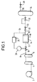
- Figure 1 is a schematic circuit diagram illustrating one embodiment of the apparatus.
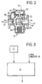
- FIG 2 is a schematic side elevation of the flow control valve in the product gas pipeline of the apparatus shown in Figure 1.
- Figure 3 is a schematic circuit diagram illustrating apparatus for controlling the position of the flow control valve in the air supply pipeline of the apparatus shown in Figure 1.
- the apparatus includes a compressor 2 of a constant displacement type.
- the compressor 2 supplies compressed air to a first receiver vessel 4 and from there to filtration vessel 6 that contain filters adapted to remove particulates and oil contamination from the air.
- the filtered air flows from the vessel 6 into an air pipeline 8 in which a first flow control valve 10 is located.
- the pipeline 8 terminates in an inlet header 12 of a vessel 14 housing semi-permeable membranes able to effect by differential permeation rates a separation as between oxygen and nitrogen.
- the membrane vessel 14 may be arranged conventionally and can be constructed with sheets of the semi-permeable membrane either laid flat, stacked or spirally wound, or more commonly, the vessel 14 contains a multiplicity fine tubes some of the membranes with the feed gas being applied either to the outside or to the bore of these tubes.
- the individual fine tubes can themselves be constructed in a number of ways, for example, they may simply be drawn tubes of the semi-permeable material. Alternatively, they may consist of a relatively porous substrate material which is coated with another material either on the inside or the outside which may itself act as a semi-permeable membrane.
- the vessel 14 has an outlet header 16 which collects non-permeate gas and enables it to flow to a product gas pipeline 20.
- the vessel 14 also has an outlet 18 for permeate gas.
- a second flow control valve 22 is located in the pipeline 20.
- the flow control valve 22 is of a kind which is able to deliver gas at a constant flow rate notwithstanding the occurrence of pressure fluctuations upstream thereof.
- the analyser 26 analyses for oxygen and is able to determine the level of oxygen impurity in the nitrogen.
- the analyser 26 conveys signals to a valve controller 28 which is able to adjust the setting of the first flow control valve 10 in a manner which will be described below.
- a pressure regulator 30 which is a valve which in operation maintains a constant pressure in the pipeline intermediate the second flow control valve 22 and itself.
- the pipeline 20 terminates in a product nitrogen receiver vessel 34 which has an outlet 36 with a manually operable flow control valve 38 disposed therein.
- the valve 38 can be set to deliver product nitrogen at the desired rate.
- the apparatus shown in Figure 1 may be set to deliver nitrogen (containing up to 1% by volume of oxygen as an impurity) at a flow rate of 50 standard cubic metres per hour to the vessel 32.
- nitrogen containing up to 1% by volume of oxygen as an impurity
- the analyser 26 will generate an appropriate signal to the valve controller 28 with the result that the valve 10 is adjusted so as to open it more, that is to say, to let gas through at a faster rate, thus reducing the pressure drop thereacross.
- the product side of the membranes in the vessel 14 are subjected to a higher pressure which in turn increases the rate of permeation of oxygen therethrough.
- the concentration of oxygen impurity in the product nitrogen thus becomes less.
- valve 22 the effect of the valve 22 is to maintain the flow rate therethrough constant even though the pressure upstream of it is increased by virtue of the opening of the valve 10. Thus, there is no increase in flow rate through the membrane vessel 14 to counteract the pressure increase on the product side of the membranes.
- the analyser 26 detects that the concentration of oxygen impurity in the product line has fallen below a chosen value (say 1% by volume) the analyser will generate a signal effective for the valve controller 28 to change the setting of the valve 10 so as to reduce the size of the passage therethrough and thus increase the pressure drop thereacross. There is hence a reduced pressure on the product size of the membranes in the vessel 14 with the result that the rate of permeation of oxygen impurity through the membranes is reduced and thus the concentration of oxygen impurity in the product gas delivered to the pipeline 20 increases.
- the setting of the valve 22 changes automatically so as to maintain the flow rate of product nitrogen that it delivers substantially constant. It can thus be appreciated that the apparatus shown in Figure 1 is capable of being set up so that it operates automatically to keep the concentration of oxygen impurity in the nitrogen product at 1% by volume irrespective of changes in the performance of the membranes.
- the valve 22 has an inlet port 40 which communicates with the outlet header 16 for product gas from the membrane vessel 14, and an outlet port 42 which is in line with the port 40 and which is in communication with the upstream side of the pressure regulating valve 30.
- a calibrated orifice 44 is mounted in the inlet port 40.
- a butterfly member 46 co-operates with the orifice 44.
- Valve members 52 and 54 co-operate with a valve seat 56 to define a generally annular opening 58 which controls the velocity of flow of gas through the valve.
- valve members 52 and 54 are able to be moved towards the valve seat 56 to reduce the size of the opening 58 by downward displacement of the shaft 50 against the bias of a compression spring 60.
- the shaft 50 is near its upper end fixed to a diaphragm 62 that forms one wall of a pilot gas chamber 64 having a gas port 66 which communicates via a conduit 68 with the upstream side of the orifice 44. Accordingly, the pressure in the chamber 64 equals that on the upstream side of the orifice 44 while the pressure on the other side of the diaphragm 62 equals the pressure on the downstream side of the orifice 44.
- a conventional oxygen analyser may be used as the analyser 26.
- the valve controller 28 may typically take the form of the apparatus shown in Figure 3.
- the controller 28 has a programmable reference signal generator 72 which feeds a (voltage) signal to a comparator 74 which compares it with the signal from the analyser 26.
- the comparator 74 comprises electrical circuits adapted to generate a control signal if there is a difference between the two signals it receives.
- the flow control valve 10 may be motorised.
- the control signal can be employed to cause the motor to rotate in a valve closing sense while if the difference in the two signals sent to the comparator is in favour of the signal produced by the analyser (that is to say that the concentration of oxygen impurity in the product gas is greater than desired) then a control signal causing the motor to rotate in a valve opening direction is generated.
- the apparatus according to the invention is thus able to supply product nitrogen at a desired purity and flow rate.
Landscapes
- Chemical & Material Sciences (AREA)
- Engineering & Computer Science (AREA)
- Analytical Chemistry (AREA)
- General Chemical & Material Sciences (AREA)
- Oil, Petroleum & Natural Gas (AREA)
- Chemical Kinetics & Catalysis (AREA)
- Separation Using Semi-Permeable Membranes (AREA)
Claims (6)
- Gerät zum Trennen einer Gasmischung mit einem Gefäßgehäuse (14), semi-permeablen Membranen, die wirksam sind, um die Mischung zu trennen, und mit einem Einlaß (12) für die zu trennende Gasmischung, einem ersten Auslaß (16) für Produktgas und einem zweiten Auslaß (18) für einen Gasstrom einer Zusammensetzung, die sich von derjenigen des Produktgases unterscheidet,
gekennzeichnet durch
ein erstes Strömungssteuerungsventil (10) zum Steuern der Gasströmung zum Einlaß (12), eine Ventilsteuerungsvorrichtung (28) zum Einstellen der Position des ersten Strömungssteuerungsventils (10) in Abhängigkeit von einer Analyse der Zusammensetzung des Produktgases, und ein zweites Strömungssteuerungsventil (22) zum Steuern der Produktgasströmung vom ersten Auslaß (16), wobei das zweite Steuerungsventil (22) in der Lage ist, Produktgas bei einer konstanten Strömungsrate über einen Bereich verschiedener Drücke stromaufwärts davon zu liefern. - Gerät wie in Anspruch 1 beansprucht,
in welchem die Ventilsteuerungsvorrichtung (28) einen Komparator (74) einschließt zum Vergleichen eines Signals für einen Gasanalysator (26), der empfindlich für die Konzentration einer Komponente im Produktgas ist, mit einem Referenzsignal (72), das das gewünschte Niveau dieser Verunreinigung repräsentiert, und zum Erzeugen eines Signals, um die Position des ersten Strömungssteuerungsventils (10) in dem Fall zu ändern, daß es eine Differenz zwischen den zwei Signalen gibt, die verglichen werden. - Gerät wie in Anspruch 1 oder Anspruch 2 beansprucht,
welches ein Aufnahmegefäß (34) zum Liefern des nicht-durchdringenden Gases als Produkt einschließt. - Gerät wie in einem der vorhergehenden Ansprüche beansprucht,
mit zusätzlich einem Kompressor (2) der zu trennenden Gasmischung, der vom Konstant-Verdrängungs-Typ ist. - Gerät wie in einem der vorhergehenden Ansprüche beansprucht,
in welchem das zweite Strömungssteuerungsventil (22) von einer Art ist, die eine Mündungsöffnung (44) stromaufwärts eines Ventilbauteils (42) und eine Pilotgaskammer (64) aufweist, welche in Verbindung mit der Stromaufwärtsseite der Mündungsöffnung (44) steht und durch eine Seite eines Diaphragmas (62) begrenzt ist, welches auf seiner anderen Seite dem Druck stromabwärts der Mündungsöffnung (44) ausgesetzt ist, wodurch bei Benutzung eine ansteigende Druckdifferenz über das Diaphragma (62) das Diaphragma (62) veranlaßt, ein Ventilbauteil (52, 54) in eine ventilschließende Richtung zu drängen, um dadurch die Strömung von Gas, das durch das Ventil (22) geliefert wird, im wesentlichen konstant zu halten. - Gerät wie in einem der vorhergehenden Ansprüche beansprucht,
mit zusätzlich einem Ventil (30), das den Druck stromaufwärts davon stromabwärts des zweiten Steuerungsventils (22) regelt, um es möglich zu machen, beim Betreiben des Geräts einen konstanten Druck zwischen dem zweiten Steuerungsventil (22) und dem Druckregelventil (30) aufrechtzuhalten.
Applications Claiming Priority (2)
| Application Number | Priority Date | Filing Date | Title |
|---|---|---|---|
| GB8916510 | 1989-07-19 | ||
| GB898916510A GB8916510D0 (en) | 1989-07-19 | 1989-07-19 | Separation of gas mixtures |
Publications (3)
| Publication Number | Publication Date |
|---|---|
| EP0409545A2 EP0409545A2 (de) | 1991-01-23 |
| EP0409545A3 EP0409545A3 (en) | 1992-08-12 |
| EP0409545B1 true EP0409545B1 (de) | 1994-04-20 |
Family
ID=10660274
Family Applications (1)
| Application Number | Title | Priority Date | Filing Date |
|---|---|---|---|
| EP90307776A Expired - Lifetime EP0409545B1 (de) | 1989-07-19 | 1990-07-17 | Trennung von Gasmischungen |
Country Status (5)
| Country | Link |
|---|---|
| US (1) | US5470379A (de) |
| EP (1) | EP0409545B1 (de) |
| DE (1) | DE69008262T2 (de) |
| GB (1) | GB8916510D0 (de) |
| ZA (1) | ZA905573B (de) |
Families Citing this family (39)
| Publication number | Priority date | Publication date | Assignee | Title |
|---|---|---|---|---|
| US5131929A (en) * | 1991-05-06 | 1992-07-21 | Permea, Inc. | Pressure control for improved gas dehydration in systems which employ membrane dryers in intermittent service |
| GB9110250D0 (en) * | 1991-05-11 | 1991-07-03 | Calor Gas Ltd | Gas supply system |
| JPH05184906A (ja) * | 1991-06-03 | 1993-07-27 | L'air Liquide | 高いフレキシビリティを有する膜型発生器 |
| US5284506A (en) * | 1992-08-26 | 1994-02-08 | L'air Liquide, Societe Anonyme Pour L'etude Et L'exploitation Des Procedes Georges Claude | Fast response high purity membrane nitrogen generator |
| US5302189A (en) * | 1992-08-26 | 1994-04-12 | L'air Liquide, Societe Anonyme Pour L'etude Et L'exploitation Des Procedes Georges Claude | Membrane nitrogen gas generator with improved flexibility |
| US5266101A (en) * | 1992-08-26 | 1993-11-30 | L'air Liquide, Societe Anonyme Pour L'etude Et L'exploitation Des Procedes Georges | Membrane gas generator in association with bulk storage for increased flexibility and productivity |
| US5762690A (en) * | 1992-11-25 | 1998-06-09 | Andrew Corporation | Dehumidifier for supplying air using variable flow rate and variable pressure in a membrane dryer |
| DE69224917T2 (de) * | 1992-12-02 | 1998-10-22 | Ebara Corp., Tokio/Tokyo | Methode und vorrichtung zur verhinderung von kontamination eines substrates oder einer substratoberfläche |
| FR2712821B1 (fr) * | 1993-11-26 | 1995-12-22 | Air Liquide | Procédé et installation de fourniture d'azote au moyen de membranes semi-perméables utilisant une géométrie membranaire variable. |
| US5649995A (en) * | 1995-03-09 | 1997-07-22 | Nitec, Inc. | Nitrogen generation control systems and methods for controlling oxygen content in containers for perishable goods |
| US5681368A (en) * | 1995-07-05 | 1997-10-28 | Andrew Corporation | Dehumidifier system using membrane cartridge |
| US5855646A (en) * | 1995-07-18 | 1999-01-05 | Verini; Nicholas A. | Method and device to monitor nitrogen gas purity during the manufacture and dispensing of nitrogen gas |
| US5588984A (en) * | 1995-07-18 | 1996-12-31 | Verini; Nicholas A. | Apparatus and method to intermittently manufacture and dispense nitrogen |
| US5688306A (en) * | 1995-07-18 | 1997-11-18 | Verini; Nicholas A. | Apparatus and method to intermittently manufacture and dispense nitrogen gas |
| US5611845A (en) * | 1995-08-22 | 1997-03-18 | Undersea Breathing Systems, Inc. | Oxygen enriched air generation system |
| DE19533407C1 (de) * | 1995-09-09 | 1997-02-06 | Dornier Gmbh | Verfahren und Vorrichtung zur Abtrennung von Kohlendioxid |
| DE19680906D2 (de) * | 1995-10-23 | 1998-10-29 | Huf Hans Joachim Dr | Verfahren zur Versorgung von Probanden mit einem erhöhten Sauerstoffangebot |
| US5700310A (en) * | 1995-12-29 | 1997-12-23 | Mg Generon, Inc. | Removal of oil from compressed gas with macroporous polymeric adsorbent |
| US5746806A (en) * | 1996-08-15 | 1998-05-05 | Nellcor Puritan Bennett Incorporated | Apparatus and method for controlling output of an oxygen concentrator |
| DE19645764C2 (de) * | 1996-11-06 | 1998-12-03 | Huf Hans Joachim Dr | System zur Luftversorgung von Druckkabinen bei Fluggeräten |
| US5814127A (en) * | 1996-12-23 | 1998-09-29 | American Air Liquide Inc. | Process for recovering CF4 and C2 F6 from a gas |
| US5989312A (en) * | 1996-12-31 | 1999-11-23 | Praxair Technology, Inc. | Membrane control system and process |
| JPH10203803A (ja) * | 1997-01-20 | 1998-08-04 | Ngk Insulators Ltd | 水素ガスの回収・精製・貯蔵装置 |
| US5911219A (en) * | 1997-04-18 | 1999-06-15 | Aylsworth; Alonzo C. | Therapeutic gas flow meter and monitor |
| GB9713989D0 (en) * | 1997-07-02 | 1997-09-10 | Boc Group Plc | Controlling atmospheres in containers |
| US6126724A (en) * | 1999-02-19 | 2000-10-03 | Hansen Inc. | Locomotive air processing apparatus |
| JP3816289B2 (ja) * | 2000-02-18 | 2006-08-30 | ナブテスコ株式会社 | 中空糸膜式除湿装置 |
| US6641643B2 (en) * | 2000-10-10 | 2003-11-04 | Generon Igs Inc. | Ceramic deoxygenation hybrid systems for the production of oxygen and nitrogen gases |
| US6746513B2 (en) * | 2002-02-19 | 2004-06-08 | L'air Liquide Societe Anonyme A Directoire Et Conseil De Surveillance Pour L'etude Et L'exploitations Des Procedes Georges Claude | Integrated membrane filter |
| US6593525B1 (en) | 2002-03-04 | 2003-07-15 | Andrew Corporation | Direct burial outdoor membrane pressurization system |
| US6719825B2 (en) * | 2002-05-07 | 2004-04-13 | Graham-White Manufacturing Company | Air drying apparatus and method |
| US7081153B2 (en) * | 2003-12-02 | 2006-07-25 | Honeywell International Inc. | Gas generating system and method for inerting aircraft fuel tanks |
| US7306646B2 (en) * | 2004-04-08 | 2007-12-11 | Parker-Hannifin Corporation | Utilization of compressor surge control air in an aircraft on-board inert gas generating system |
| US7387659B2 (en) * | 2005-02-01 | 2008-06-17 | Parker Hannifin Corporation | Pneumatically operated automatic shutoff circuit for controlling the generation of gas |
| US7588612B2 (en) * | 2005-07-19 | 2009-09-15 | Bank Of America, N.A. | Mobile nitrogen generation device |
| US7481869B2 (en) * | 2005-08-17 | 2009-01-27 | Andrew Llc | Dry gas production systems for pressurizing a space and methods of operating such systems to produce a dry gas stream |
| US9592171B2 (en) | 2011-08-25 | 2017-03-14 | Undersea Breathing Systems, Inc. | Hyperbaric chamber system and related methods |
| BE1020553A3 (nl) * | 2012-03-19 | 2013-12-03 | Atlas Copco Airpower Nv | Inrichting en werkwijze voor het scheiden van gassen. |
| CN104727990B (zh) * | 2015-03-06 | 2017-03-01 | 吉林大学 | 一种分子膜式车用氮氧分离装置及分离方法 |
Family Cites Families (18)
| Publication number | Priority date | Publication date | Assignee | Title |
|---|---|---|---|---|
| US3339341A (en) * | 1965-12-22 | 1967-09-05 | Du Pont | Fluid separation process and apparatus |
| US3922149A (en) * | 1974-01-30 | 1975-11-25 | Garrett Corp | Oxygen air enrichment method |
| US3930814A (en) * | 1974-11-27 | 1976-01-06 | General Electric Company | Process for producing oxygen-enriched gas |
| US3930813A (en) * | 1974-11-27 | 1976-01-06 | General Electric Company | Process for producing nitrogen dioxide-free oxygen-enriched gas |
| FR2403819A1 (fr) * | 1977-09-27 | 1979-04-20 | Ravier Philippe | Procede et installation de separation des gaz par diffusion gazeuse |
| US4397661A (en) * | 1980-06-27 | 1983-08-09 | Monsanto Company | Gas permeation apparatus having permeate rate controlled valving |
| EP0051469A1 (de) * | 1980-11-03 | 1982-05-12 | Monsanto Company | Verfahren zum Abtrennen von Gas aus einer Gasmischung |
| EP0060693A3 (de) * | 1981-03-13 | 1983-11-16 | Monsanto Company | Verfahren zur Abtrennung eines Gases aus einer Gasmischung |
| EP0075431A1 (de) * | 1981-09-17 | 1983-03-30 | Monsanto Company | Verfahren zum Abtrennen eines Gases aus einer Mischung von Gasen |
| US4421529A (en) * | 1982-07-02 | 1983-12-20 | The Dow Chemical Company | Membrane system for intermittent gas separation |
| US4472176A (en) * | 1983-08-01 | 1984-09-18 | Resource Systems, Inc. | Apparatus and method for the production of pure hydrogen from a hydrogen-containing crude gas |
| JPS62191404A (ja) * | 1986-02-19 | 1987-08-21 | Hitachi Ltd | 空気分離装置 |
| JPS63236517A (ja) * | 1987-03-24 | 1988-10-03 | Ube Ind Ltd | 混合ガスの除湿方法 |
| US4806132A (en) * | 1987-06-23 | 1989-02-21 | Union Carbide Corporation | Turndown control method for membrane separation systems |
| JPS6418425A (en) * | 1987-07-13 | 1989-01-23 | Toray Industries | Generator of oxygen-enriched air |
| US4857082A (en) * | 1988-09-15 | 1989-08-15 | Air Products And Chemicals, Inc. | Membrane unit turn-down control system |
| US4863492A (en) * | 1988-11-28 | 1989-09-05 | Uop | Integrated membrane/PSA process and system |
| US4944776A (en) * | 1989-10-05 | 1990-07-31 | Andrew Corporation | Dehumidifier for waveguide system |
-
1989
- 1989-07-19 GB GB898916510A patent/GB8916510D0/en active Pending
-
1990
- 1990-07-16 ZA ZA905573A patent/ZA905573B/xx unknown
- 1990-07-17 DE DE69008262T patent/DE69008262T2/de not_active Expired - Fee Related
- 1990-07-17 EP EP90307776A patent/EP0409545B1/de not_active Expired - Lifetime
-
1993
- 1993-01-07 US US08/001,946 patent/US5470379A/en not_active Expired - Fee Related
Also Published As
| Publication number | Publication date |
|---|---|
| EP0409545A3 (en) | 1992-08-12 |
| US5470379A (en) | 1995-11-28 |
| GB8916510D0 (en) | 1989-09-06 |
| DE69008262T2 (de) | 1994-08-04 |
| EP0409545A2 (de) | 1991-01-23 |
| DE69008262D1 (de) | 1994-05-26 |
| ZA905573B (en) | 1991-08-28 |
Similar Documents
| Publication | Publication Date | Title |
|---|---|---|
| US5470379A (en) | Membrane plant: automatic control of | |
| US4857082A (en) | Membrane unit turn-down control system | |
| US5281253A (en) | Multistage membrane control system and process | |
| CN104797322B (zh) | 采用膜的气体分离装置的气体组成控制 | |
| US5053058A (en) | Control process and apparatus for membrane separation systems | |
| US4806132A (en) | Turndown control method for membrane separation systems | |
| US8444749B2 (en) | Method and system for membrane-based gas recovery | |
| US5284506A (en) | Fast response high purity membrane nitrogen generator | |
| US5507855A (en) | Process and installation for supplying nitrogen with the aid of semi-permeable membranes using a variable membrane geometry | |
| EP0129304B1 (de) | Gastrennungssysteme von Molekularsiebtyp | |
| EP4556105A1 (de) | Gastrennungssystem und verfahren zur herstellung von angereichertem gas | |
| EP0585159B1 (de) | Verfahren zur Herstellung von Stickstoff mit Hilfe einer Membrane | |
| US5342637A (en) | Method for conditioning the atmosphere in a storage chamber for organic harvested produce | |
| JPH04227019A (ja) | 改善された膜/脱酸素方法及び装置 | |
| CA1335426C (en) | Apparatus for the separation of gas mixtures | |
| US5125937A (en) | Reversible membrane plant | |
| JPS59172021A (ja) | 酸素分圧制御装置 | |
| JP2015513999A (ja) | ガス分離装置及び方法 | |
| JPH07112112A (ja) | 天然ガス中の特定成分の分離方法及び装置 | |
| TWI818307B (zh) | 氣體純化提取設備 | |
| JP2002172318A (ja) | 超純水の比抵抗調整装置及び調整方法 | |
| KR930003239B1 (ko) | 멤브레인 분리 시스템을 위한 턴다운 제어방법 | |
| JP2521437Y2 (ja) | 窒素コンプレッサー | |
| JPH0268112A (ja) | 膜分離システム用負荷調整制御方法 | |
| DE3887985T2 (de) | Teillastregelmethode für Membrantrennsysteme. |
Legal Events
| Date | Code | Title | Description |
|---|---|---|---|
| PUAI | Public reference made under article 153(3) epc to a published international application that has entered the european phase |
Free format text: ORIGINAL CODE: 0009012 |
|
| AK | Designated contracting states |
Kind code of ref document: A2 Designated state(s): BE DE ES FR GB IT NL SE |
|
| PUAL | Search report despatched |
Free format text: ORIGINAL CODE: 0009013 |
|
| AK | Designated contracting states |
Kind code of ref document: A3 Designated state(s): BE DE ES FR GB IT NL SE |
|
| 17P | Request for examination filed |
Effective date: 19930105 |
|
| 17Q | First examination report despatched |
Effective date: 19930623 |
|
| GRAA | (expected) grant |
Free format text: ORIGINAL CODE: 0009210 |
|
| ITF | It: translation for a ep patent filed | ||
| AK | Designated contracting states |
Kind code of ref document: B1 Designated state(s): BE DE ES FR GB IT NL SE |
|
| PG25 | Lapsed in a contracting state [announced via postgrant information from national office to epo] |
Ref country code: SE Free format text: LAPSE BECAUSE OF FAILURE TO SUBMIT A TRANSLATION OF THE DESCRIPTION OR TO PAY THE FEE WITHIN THE PRESCRIBED TIME-LIMIT Effective date: 19940420 |
|
| ET | Fr: translation filed | ||
| REF | Corresponds to: |
Ref document number: 69008262 Country of ref document: DE Date of ref document: 19940526 |
|
| PGFP | Annual fee paid to national office [announced via postgrant information from national office to epo] |
Ref country code: SE Payment date: 19940614 Year of fee payment: 5 |
|
| PG25 | Lapsed in a contracting state [announced via postgrant information from national office to epo] |
Ref country code: ES Free format text: LAPSE BECAUSE OF FAILURE TO SUBMIT A TRANSLATION OF THE DESCRIPTION OR TO PAY THE FEE WITHIN THE PRESCRIBED TIME-LIMIT Effective date: 19940731 |
|
| PLBE | No opposition filed within time limit |
Free format text: ORIGINAL CODE: 0009261 |
|
| STAA | Information on the status of an ep patent application or granted ep patent |
Free format text: STATUS: NO OPPOSITION FILED WITHIN TIME LIMIT |
|
| 26N | No opposition filed | ||
| PGFP | Annual fee paid to national office [announced via postgrant information from national office to epo] |
Ref country code: ES Payment date: 19970717 Year of fee payment: 8 |
|
| REG | Reference to a national code |
Ref country code: GB Ref legal event code: IF02 |
|
| PGFP | Annual fee paid to national office [announced via postgrant information from national office to epo] |
Ref country code: FR Payment date: 20020702 Year of fee payment: 13 |
|
| PGFP | Annual fee paid to national office [announced via postgrant information from national office to epo] |
Ref country code: NL Payment date: 20020703 Year of fee payment: 13 |
|
| PGFP | Annual fee paid to national office [announced via postgrant information from national office to epo] |
Ref country code: GB Payment date: 20020710 Year of fee payment: 13 |
|
| PGFP | Annual fee paid to national office [announced via postgrant information from national office to epo] |
Ref country code: DE Payment date: 20020730 Year of fee payment: 13 |
|
| PGFP | Annual fee paid to national office [announced via postgrant information from national office to epo] |
Ref country code: BE Payment date: 20020802 Year of fee payment: 13 |
|
| PG25 | Lapsed in a contracting state [announced via postgrant information from national office to epo] |
Ref country code: GB Free format text: LAPSE BECAUSE OF NON-PAYMENT OF DUE FEES Effective date: 20030717 |
|
| PG25 | Lapsed in a contracting state [announced via postgrant information from national office to epo] |
Ref country code: BE Free format text: LAPSE BECAUSE OF NON-PAYMENT OF DUE FEES Effective date: 20030731 |
|
| BERE | Be: lapsed |
Owner name: THE *BOC GROUP P.L.C. Effective date: 20030731 |
|
| PG25 | Lapsed in a contracting state [announced via postgrant information from national office to epo] |
Ref country code: NL Free format text: LAPSE BECAUSE OF NON-PAYMENT OF DUE FEES Effective date: 20040201 |
|
| PG25 | Lapsed in a contracting state [announced via postgrant information from national office to epo] |
Ref country code: DE Free format text: LAPSE BECAUSE OF NON-PAYMENT OF DUE FEES Effective date: 20040203 |
|
| GBPC | Gb: european patent ceased through non-payment of renewal fee |
Effective date: 20030717 |
|
| PG25 | Lapsed in a contracting state [announced via postgrant information from national office to epo] |
Ref country code: FR Free format text: LAPSE BECAUSE OF NON-PAYMENT OF DUE FEES Effective date: 20040331 |
|
| NLV4 | Nl: lapsed or anulled due to non-payment of the annual fee |
Effective date: 20040201 |
|
| REG | Reference to a national code |
Ref country code: FR Ref legal event code: ST |
|
| PG25 | Lapsed in a contracting state [announced via postgrant information from national office to epo] |
Ref country code: IT Free format text: LAPSE BECAUSE OF NON-PAYMENT OF DUE FEES;WARNING: LAPSES OF ITALIAN PATENTS WITH EFFECTIVE DATE BEFORE 2007 MAY HAVE OCCURRED AT ANY TIME BEFORE 2007. THE CORRECT EFFECTIVE DATE MAY BE DIFFERENT FROM THE ONE RECORDED. Effective date: 20050717 |