EP0408059B1 - Steuergerät für einen Fahrzeugwechselstromgenerator - Google Patents
Steuergerät für einen Fahrzeugwechselstromgenerator Download PDFInfo
- Publication number
- EP0408059B1 EP0408059B1 EP90113450A EP90113450A EP0408059B1 EP 0408059 B1 EP0408059 B1 EP 0408059B1 EP 90113450 A EP90113450 A EP 90113450A EP 90113450 A EP90113450 A EP 90113450A EP 0408059 B1 EP0408059 B1 EP 0408059B1
- Authority
- EP
- European Patent Office
- Prior art keywords
- output
- dummy load
- voltage
- rectifier
- generator
- Prior art date
- Legal status (The legal status is an assumption and is not a legal conclusion. Google has not performed a legal analysis and makes no representation as to the accuracy of the status listed.)
- Expired - Lifetime
Links
Images
Classifications
-
- H—ELECTRICITY
- H02—GENERATION; CONVERSION OR DISTRIBUTION OF ELECTRIC POWER
- H02J—ELECTRIC POWER NETWORKS; CIRCUIT ARRANGEMENTS OR SYSTEMS FOR SUPPLYING OR DISTRIBUTING ELECTRIC POWER; SYSTEMS FOR STORING ELECTRIC ENERGY
- H02J7/00—Circuit arrangements for charging or discharging batteries or for supplying loads from batteries
- H02J7/14—Circuit arrangements for charging or discharging batteries or for supplying loads from batteries for charging batteries from dynamo-electric generators driven at varying speed, e.g. on vehicle
- H02J7/16—Regulation of the charging current or voltage by variation of field
-
- H—ELECTRICITY
- H02—GENERATION; CONVERSION OR DISTRIBUTION OF ELECTRIC POWER
- H02J—ELECTRIC POWER NETWORKS; CIRCUIT ARRANGEMENTS OR SYSTEMS FOR SUPPLYING OR DISTRIBUTING ELECTRIC POWER; SYSTEMS FOR STORING ELECTRIC ENERGY
- H02J7/00—Circuit arrangements for charging or discharging batteries or for supplying loads from batteries
- H02J7/60—Circuit arrangements for charging or discharging batteries or for supplying loads from batteries including safety or protection arrangements
- H02J7/64—Circuit arrangements for charging or discharging batteries or for supplying loads from batteries including safety or protection arrangements against overvoltage
-
- Y—GENERAL TAGGING OF NEW TECHNOLOGICAL DEVELOPMENTS; GENERAL TAGGING OF CROSS-SECTIONAL TECHNOLOGIES SPANNING OVER SEVERAL SECTIONS OF THE IPC; TECHNICAL SUBJECTS COVERED BY FORMER USPC CROSS-REFERENCE ART COLLECTIONS [XRACs] AND DIGESTS
- Y02—TECHNOLOGIES OR APPLICATIONS FOR MITIGATION OR ADAPTATION AGAINST CLIMATE CHANGE
- Y02T—CLIMATE CHANGE MITIGATION TECHNOLOGIES RELATED TO TRANSPORTATION
- Y02T10/00—Road transport of goods or passengers
- Y02T10/60—Other road transportation technologies with climate change mitigation effect
- Y02T10/70—Energy storage systems for electromobility, e.g. batteries
Definitions
- This invention relates to a control device for a vehicle AC generator.
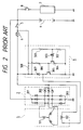
- FIG. 2 One example of a conventional control device for a vehicle AC generator is as shown in Fig. 2.
- an AC generator 1 has an armature coil 101 and a field coil 102.
- a rectifier 2 for rectifying AC output voltages is connected to the AC generator 1.
- the rectifier 2 has a main output terminal 201, an auxiliary output terminal 202, and a ground terminal 203.
- One end of the field coil 102 is connected to a voltage regulator 3.
- the voltage regulator 3 comprises: voltage division resistors 301 and 302 for voltage detection; a control transistor 304 whose base electrode is connected through a Zener diode 303 to the connecting point of the two voltage division resistors 301 and 302; a power transistor 305 which is controlled by the transistor 304; a resistor 306; a suppression diode 307; and an initial exciting resistor 308.
- the main output terminal 201 of the rectifier 2 is connected to a battery 4.
- the other end of the field coil 102 is connected to the auxiliary output terminal 202 of the rectifier 2, and it is further connected through the initial exciting resistor 308 and a key switch 5 to the positive terminal of the battery 4.
- a display lamp 6 is disposed in parallel with the initial exciting resistor 308.
- the positive terminal of the battery 4 is connected through a load switch 8 to a vehicle electrical load 7.
- the conventional control device thus designed operates as follows: When the key switch 5 is turned on, an initial exciting current flows in the field coil 102 through the parallel circuit of the display lamp 6 and the initial exciting resistor 308, so that the display lamp 6 is turned on. When the field current flows and the generator 1 is driven, a power generation is carried out, so that AC voltage is induced across the armature coil 101. As a result, the potential difference across the display lamp 6 becomes 0 V, so that the latter 6 is turned off.
- the AC voltage induced on the armature coil 101 is rectified by the rectifier 2 and applied to the battery 4 to charge the latter 4. If, in this operation, the output voltage of the generator 1 is lower than a predetermined value, the voltage provided by the voltage division resistors 301 and 302 is also low. Accordingly, the Zener diode 303 is non-conductive, and the controlling transistor is also non-conductive, so that the power transistor is conductive. As a result, the field current flowing in the field coil 102 is increased, and the output voltage of the generator 1 is increased accordingly. When, on the other hand, the output voltage of the generator 1 is higher than the predetermined value, the voltage provided by the voltage division resistors 301 and 302 is also high.
- the Zener diode is rendered conductive, and the controlling transistor 304 is also rendered conductive, so that the power transistor 305 is rendered non-conductive. Therefore, the field current is decreased, and the output voltage of the generator 1 is decreased accordingly.
- the above-described operations are repeatedly carried out until the output voltage of the generator 1 reaches the predetermined value.
- the suppression diode 307 is to absorb the surge induced on the field coil 102.
- the power transistor 305 When, in the above-described conventional device, the power transistor 305 is short-circuited, or the one end of the field coil 102 which is to be controlled in an on-off mode is grounded with a metallic foreign matter or the like, the on-off control of the field current cannot be performed any longer, so that the field current is allowed to flow continuously. As a result, the output voltage of the generator 1 is raised abnormally high, and the battery is charged excessively. In this case, the display lamp 6 gives no alarm for this abnormal condition. If this over-charging occurs during high speed operation, and lasts for a long time, then a large quantity of hydrogen gas is produced from the battery electrolyte to burst the battery at worst. During the driving of the vehicle at night, the excessively high voltage may burn out the filaments of the head lamps, thus making it impossible to drive the vehicle. In addition, the excessively high voltage may break the engine controlling computer, thus making it impossible to control the engine.
- a device with the features of the preamble of claim 1 is shown in DE-A-1 538 357.
- an object of this invention is to eliminate the above-described difficulties accompanying a conventional control device for a vehicle AC generator. More specifically, an object of the invention is to prevent a vehicle electrical load including a battery from being damaged when a vehicle AC generator outputs abnormally high voltages as its control means becomes out of order.
- a vehicle AC generator control device comprising: an AC generator including a field coil; a rectifier for rectifying an AC output of said AC generator; a battery connected to an output terminal of said rectifier; a voltage regulator including a switching element series-connected to said field coil, said voltage regulator detecting a terminal voltage of said rectifier or battery to operate said switching element to control a field current of said field coil to adjust an output voltage of said generator to a predetermined value; a dummy load unit including a dummy load, and an overvoltage limiter which detects when said output voltage of said AC generator exceeds a set value, to energise said dummy load unit, so that said dummy load unit is connected to an output terminal of said rectifier thereby to suppress abnormal rise of said output voltage, wherein the capacity of the dummy load is balanced with an output capacity of said AC generator and the dummy load is held continuously connected to said output terminal of said rectifier until a key switch is opened, characterised in that the overvoltage
- the overvoltage limiter When the voltage regulator becomes out of order, so that the output voltage of the generator is increased abnormally high exceeding the set value, the overvoltage limiter operates to energize the dummy load unit, so that the dummy load is connected to the rectifier.
- the capacity of the dummy load is so selected to be in balance with the output capacity of the generator. Therefore, upon connection of the dummy load, the amount of surplus output voltage is consumed thereby, to suppress the abnormal rise of the output voltage.
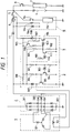
- Fig. 1 is a circuit diagram showing one example of a control device for a vehicle AC generator according to this invention.
- an AC generator 1 comprises an armature coil 101 and a field coil 102, and is connected to a rectifier 2.
- the rectifier 2 has a main output terminal 201, an auxiliary output terminal 202, and a ground terminal 203.
- the main output terminal 201 is connected to a battery 4.
- One end of the field coil 102 is connected to a voltage regulator 3, which comprises: voltage division resistors 301 and 302; a control transistor 304 whose base is connected through a Zener diode 303 to the connecting points of the voltage division resistors 301 and 302: a power transistor 305 which is controlled by the control transistor 304; a resistor 306; a suppression diode 307; and an initial exciting resistor 308.
- the other end of the field coil 102 is connected to the auxiliary output terminal 202, and through the initial exciting resistor 308 and a key switch 5 to the positive terminal of the battery 4.
- a display lamp 6 is provided in parallel with the initial exciting resistor 308.
- a vehicle electrical load 7 is connected through a load switch 8 to the positive terminal of the battery 4.
- the auxiliary output terminal 202 of the rectifier 2 is connected to an overvoltage limiter 9.
- the latter 9 comprises: voltage division resistors 901 and 902 for output voltage detection; a Zener diode 903 connected to the connecting point of the voltage division resistors 901 and 902; an output transistor 904 whose base is connected to the Zener diode 903; and a hold circuit consisting of a transistor 905 and resistors 906 and 907.
- the collector of the output transistor 904 is connected to a diode 908.
- the overvoltage limiter 9 further comprises a transistor 911 whose base is connected through a resistor 909 and a Zener diode 910 to the collector of the power transistor 305 of the voltage regulator 3.
- the collector of the transistor 911 is connected to the connecting point of the voltage division resistors 901 and 902.
- the control device further includes a dummy load unit 10, which comprises: a diode 10a for applying current to a display lamp 6; a coil member 10b for operating contact means 10c; the contact means 10c which is closed when the coil member 10b is energized; and a dummy load 10d connected to the positive terminal (output end of the generator) of the battery 4 through the contact means 10C.
- the diode 10a and the coil member 10b of the dummy load unit 10 are connected to the collector of the output transistor 904.
- reference numeral 11 designates a reverse blocking diode.
- control device In the control device, the operation from switching the key switch 5 to the electric power generation, and the voltage regulating operation are the same as those in the above-described conventional control device.
- the contact means 10c of the dummy load unit 10 is closed, so that the dummy load 10d is connected to the output terminal of the generator.
- the capacity of the dummy load is so selected to be in balance with the output capacity of the generator 1.
- the amount of surplus electric power is consumed by the dummy load 10d, so that the abnormal rise of the voltage is prevented.
- current is applied to the display lamp 6 through the diode 10a, so that the display lamp 6 is turned on to give an alarm to the driver for the abnormal condition.
- the output transistor 904 of the overvoltage limiter 9 is rendered conductive, then a base current flows in the transistor 905 forming the hold circuit, so that the transistor 905 is rendered conductive.
- the division voltage is increased with the aid of the resistor 906 connected to the collector of the transistor 905, as a result of which the Zener diode 903 is rendered conductive, whereby the output transistor 904 is held rendered conductive. This holding operation lasts until the key switch 5 is turned off.
- the power transistor 305 of the voltage regulator 3 When a large vehicle electric load is disconnected, the power transistor 305 of the voltage regulator 3 is non-conductive, so that its collector potential is high. This high potential is detected by the resistor 909 and the Zener diode 910 of the overvoltage limiter 9, so that the transistor 911 connected to the Zener diode 910 is rendered conductive, whereby the voltage dividing function of the voltage division resistors 901 and 902 is made ineffective. This eliminates the erroneous connection of the dummy load 10 when such a load is disconnected.
- the control device of the invention is so designed that, when the output voltage of the generator is raised abnormally high exceeding the predetermined value because the voltage regulator does not work, the abnormally high voltage is detected by the logic means in association with the operating condition of the voltage regulator, so that the dummy load balanced with the output capacity of the generator is connected to the output terminal of the rectifier, whereby the abnormal rise of the output voltage is prevented.
- This will prevent the occurrences of serious difficulties or troubles that for instance the battery is excessively charged, and broken, the filaments of the head lamps are burnt out to make it impossible for the operator to drive the vehicle any longer at high, the engine controlling computer is broken to make it impossible to control the engine.
- the control device of the invention operates as security means to perform protecting and warning controls with high accuracy.
Landscapes
- Engineering & Computer Science (AREA)
- Power Engineering (AREA)
- Control Of Eletrric Generators (AREA)
Claims (5)
- Fahrzeug-Wechselstromgenerator-Steuervorrichtung, die folgendes aufweist:
einen Wechselstromgenerator (1) mit einer Erregerspule (102);
einen Gleichrichter (2) zum Gleichrichten einer Wechselstromausgabe des Wechselstromgenerators;
eine Batterie (4), die an einem Ausgangsanschluß des Gleichrichters angeschlossen ist;
einen Spannungsregler (3) mit einem Schaltelement (304, 305), der seriell zu der Erregerwicklung angeschlossen ist, wobei der Spannungsregler eine Anschlußspannung des Gleichrichters oder der Batterie erfaßt, um das Schaltelement zu betätigen, um einen Erregerstrom der Erregerwicklung zu steuern, um eine Ausgangsspannung des Generators auf einen vorbestimmten Wert einzustellen;
eine Scheinlast-(10)-Einheit einer Scheinlast, und
einen Überspannungsbegrenzer (9), der erfaßt, wenn die Ausgangsspannung des Wechselstromgenerators einen eingestellten Wert übersteigt, um die Scheinlast-Einheit mit Energie zu versorgen, so daß die Scheinlast-Einheit an einen Ausgangsanschluß des Gleichrichters angeschlossen wird, um dadurch einen anormalen Anstieg der Ausgangsspannung zu unterdrücken, wobei
die Kapazität der Scheinlast (10d) mit einer Ausgangskapazität des Wechselstromgenerators im Gleichgewicht ist, und die Scheinlast kontinuierlich an dem Ausgangsanschluß des Gleichrichters (2) angeschlossen gehalten wird, bis ein Schlüsselschalter (5) geöffnet wird,
dadurch gekennzeichnet, daß der Überspannungsbegrenzer (9) einen Ausgangstransistor (904) enthält, um die Versorgung der Scheinlast-Einheit (10) mit Energie zu steuern, wenn der Ausgangstransistor (904) in seinem leitenden Zustand ist,
die Scheinlast (10d) an der Verbindungsstelle des Ausgangsanschlusses des Gleichrichters (2) und der Batterie angeschlossen ist, und die Kapazität der Scheinlast (10, 10d) so ausgelegt ist, daß die Menge an überschüssiger Ausgangsspannung dadurch verbraucht wird, wenn sie an dem Gleichrichter (2) angeschlossen ist,
eine Anzeigelampe (96) an dem Ausgangstransistor (904) angeschlossen ist, um einen anormalen Zustand anzuzeigen, wenn der Ausgangstransistor (904) mit Energie versorgt wird, und
einen Detektor (910, 911) für hohes Potential an dem Schaltelement (304, 305) angeschlossen ist, um den Ausgangstransistor (904) des Überspannungsbegrenzers (9) unwirksam werden zu lassen, wenn das Schaltelement (305) nicht leitend ist. - Fahrzeug-Wechselstromgenerator-Steuervorrichtung nach Anspruch 1, wobei die Scheinlast-Einheit weiterhin eine Diode (10a) enthält zum Zuführen von Strom zu einer Anzeigelampe (6), eine Kontakteinrichtung (10c), und ein Spulenelement (10b) zum Betätigen der Kontakteinrichtung (10c), wobei die Kontakteinrichtung (10c) geschlossen wird, wenn das Spulenelement (10b) mit Energie versorgt wird, so daß die Scheinlast (10d) der Scheinlast-Einheit (10) an den Ausgangsanschluß des Gleichrichters (2) angeschlossen wird.
- Fahrzeug-Wechselstromgenerator-Steuervorrichtung nach Anspruch 2, wobei der Überspannungsbegrenzer einen ersten und einen zweiten Spannungsteilungs-Widerstand (901, 902) enthält zum Erfassen einer Ausgangsspannung an dem Ausgangsanschluß des Gleichrichters, und eine erste Zener-Diode (903), die an einer Verbindungsstelle des ersten und des zweiten Spannungsteilungs-Widerstands angeschlossen ist, um den eingestellten Wert einzustellen, und wobei der Basisanschluß des Ausgangstransistors (904) an der ersten Zener-Diode (903) angeschlossen ist, wobei der Ausgangstransistor (904) das Spulenelement (10b) der Scheinlast-Einheit (10) mit Energie versorgt, wenn die durch den ersten und den zweiten Spannungsteilungs-Widerstand (901, 902) erfaßte Ausgangsspannung den eingestellten Wert übersteigt.
- Fahrzeug-Wechselstromgenerator-Steuervorrichtung nach Anspruch 3, wobei der Überspannungsbegrenzer weiterhin einen Halte-Schaltkreis enthält, der aus einem zweiten Transistor (905) und einem dritten und einem vierten Widerstand (906, 907) besteht, die jeweils an dem Ausgangstransistor und der ersten Zener-Diode (903) angeschlossen sind, wobei der Halte-Schaltkreis eine Energieversorgungsoperation des Ausgangstransistors (904) hält.
- Fahrzeug-Wechselstromgenerator-Steuervorrichtung nach Anspruch 4, wobei der Überspannungsbegrenzer weiterhin einen dritten Transistor (911) enthält, dessen Basisanschluß an dem Schaltelement (305) des Spannungsreglers (3) über eine zweite Zener-Diode (910) und einen fünften Widerstand (909) angeschlossen ist, wobei der dritte Transistor (911) leitend gemacht wird, wenn das Schaltelement (305) des Spannungsreglers (6) nicht leitend ist, so daß die Scheinlast-Einheit (10) nicht an den Gleichrichter (2) angeschlossen wird.
Applications Claiming Priority (2)
| Application Number | Priority Date | Filing Date | Title |
|---|---|---|---|
| JP180954/89 | 1989-07-13 | ||
| JP1180954A JPH0349598A (ja) | 1989-07-13 | 1989-07-13 | 車両用交流発電機の制御装置 |
Publications (3)
| Publication Number | Publication Date |
|---|---|
| EP0408059A2 EP0408059A2 (de) | 1991-01-16 |
| EP0408059A3 EP0408059A3 (en) | 1992-03-18 |
| EP0408059B1 true EP0408059B1 (de) | 1995-12-06 |
Family
ID=16092182
Family Applications (1)
| Application Number | Title | Priority Date | Filing Date |
|---|---|---|---|
| EP90113450A Expired - Lifetime EP0408059B1 (de) | 1989-07-13 | 1990-07-13 | Steuergerät für einen Fahrzeugwechselstromgenerator |
Country Status (4)
| Country | Link |
|---|---|
| US (1) | US5089766A (de) |
| EP (1) | EP0408059B1 (de) |
| JP (1) | JPH0349598A (de) |
| DE (1) | DE69023974T2 (de) |
Families Citing this family (22)
| Publication number | Priority date | Publication date | Assignee | Title |
|---|---|---|---|---|
| DE4039404A1 (de) * | 1990-12-10 | 1992-06-11 | Sgs Thomson Microelectronics | Ueberspannungsschutzvorrichtung |
| US5592074A (en) * | 1992-06-26 | 1997-01-07 | Canon Kabushiki Kaisha | Battery power supply system |
| JPH08126223A (ja) * | 1994-10-26 | 1996-05-17 | Mitsubishi Electric Corp | 交流発電機の制御装置 |
| JP3299398B2 (ja) * | 1994-11-15 | 2002-07-08 | 三菱電機株式会社 | 車両用交流発電機の出力制御装置 |
| JP3302846B2 (ja) * | 1994-11-30 | 2002-07-15 | 三菱電機株式会社 | 電源装置 |
| JP3491797B2 (ja) * | 1995-12-05 | 2004-01-26 | 株式会社デンソー | 車両用発電装置 |
| US6170029B1 (en) | 1998-09-30 | 2001-01-02 | International Business Machines Corporation | Voltage overshoot control in hot plug system |
| US6229334B1 (en) | 1998-09-30 | 2001-05-08 | International Business Machines Corporation | Voltage overshoot control |
| FR2798013B1 (fr) * | 1999-08-30 | 2008-06-13 | Mitsubishi Electric Corp | Systeme de commande pour alternateur |
| US6917179B2 (en) * | 2001-10-25 | 2005-07-12 | Toyota Jidosha Kabushiki Kaisha | Load driver and control method for safely driving DC load and computer-readable recording medium with program recorded thereon for allowing computer to execute the control |
| JP3465246B2 (ja) * | 2001-11-08 | 2003-11-10 | 学校法人東海大学 | 流体発電装置 |
| JP3835363B2 (ja) * | 2002-07-09 | 2006-10-18 | 株式会社デンソー | 車両用発電制御装置 |
| JP3997969B2 (ja) * | 2002-12-10 | 2007-10-24 | 株式会社デンソー | 発電制御装置 |
| US6876177B2 (en) * | 2003-02-04 | 2005-04-05 | General Motors Corporation | Load dump transient voltage controller |
| JP2004357428A (ja) * | 2003-05-29 | 2004-12-16 | Mitsubishi Electric Corp | 発電機制御装置 |
| JP2005349995A (ja) * | 2004-06-11 | 2005-12-22 | Shimano Inc | 自転車用電気機器の保護回路 |
| JP2007037262A (ja) * | 2005-07-26 | 2007-02-08 | Mitsubishi Electric Corp | インバータ一体型回転電機 |
| US7944183B2 (en) * | 2006-03-07 | 2011-05-17 | Mitsubishi Denki Kabushiki Kaisha | Output voltage controller for AC vehicle generator |
| JP2007288916A (ja) * | 2006-04-17 | 2007-11-01 | Yamaha Motor Co Ltd | 電圧調整回路、および電圧調整回路を備えた自動二輪車 |
| US8289005B2 (en) * | 2008-09-30 | 2012-10-16 | C.E. Niehoff & Co. | Field transient suppression system and method |
| US8314588B2 (en) * | 2009-11-18 | 2012-11-20 | Honeywell International Inc. | Control system for battery charge maintenance in a power system with main AC generator control |
| CN104113038A (zh) * | 2013-04-16 | 2014-10-22 | 鸿富锦精密电子(天津)有限公司 | 保护电路 |
Citations (1)
| Publication number | Priority date | Publication date | Assignee | Title |
|---|---|---|---|---|
| DE1538357A1 (de) * | 1957-10-08 | 1969-08-14 | Bosch Gmbh Robert | UEberspannungsschutzeinrichtung fuer einen mit einem Halbleiter-Spannungsregler versehenen Generator |
Family Cites Families (13)
| Publication number | Priority date | Publication date | Assignee | Title |
|---|---|---|---|---|
| GB1239766A (en) * | 1968-01-29 | 1971-07-21 | Lucas Industries Ltd | Battery charging systems |
| JPS55157942A (en) * | 1979-05-25 | 1980-12-09 | Nippon Denso Co | Automotive generator generation control device |
| JPS55181454U (de) * | 1979-06-12 | 1980-12-26 | ||
| US4277738A (en) * | 1979-06-18 | 1981-07-07 | General Motors Corporation | Generator voltage regulator |
| JPS5743528A (en) * | 1980-08-29 | 1982-03-11 | Nippon Denso Co | Generation display unit for automotive generator |
| US4459631A (en) * | 1982-10-28 | 1984-07-10 | General Motors Corporation | Transient over-voltage protection circuit |
| JPS59148538A (ja) * | 1983-02-10 | 1984-08-25 | 株式会社日立製作所 | 充電発電機用電圧調整装置 |
| US4658200A (en) * | 1983-03-25 | 1987-04-14 | Mitsubishi Denki Kabushiki Kaisha | Protection circuit for voltage regulator of vehicle mounted generator |
| US4629966A (en) * | 1984-11-13 | 1986-12-16 | Electro-Tech, Inc. | Dual current limiting voltage regulator |
| JPS62102396A (ja) * | 1985-10-29 | 1987-05-12 | 三菱電機株式会社 | 路線バス運行管理方法 |
| JPH0545120Y2 (de) * | 1985-11-18 | 1993-11-17 | ||
| JPH0832126B2 (ja) * | 1986-01-27 | 1996-03-27 | 三菱電機株式会社 | 回路しや断器の電源装置 |
| JPH0810969B2 (ja) * | 1986-11-13 | 1996-01-31 | 三菱電機株式会社 | 車両用交流発電機の制御装置 |
-
1989
- 1989-07-13 JP JP1180954A patent/JPH0349598A/ja active Pending
-
1990
- 1990-07-12 US US07/551,344 patent/US5089766A/en not_active Expired - Lifetime
- 1990-07-13 DE DE69023974T patent/DE69023974T2/de not_active Expired - Fee Related
- 1990-07-13 EP EP90113450A patent/EP0408059B1/de not_active Expired - Lifetime
Patent Citations (1)
| Publication number | Priority date | Publication date | Assignee | Title |
|---|---|---|---|---|
| DE1538357A1 (de) * | 1957-10-08 | 1969-08-14 | Bosch Gmbh Robert | UEberspannungsschutzeinrichtung fuer einen mit einem Halbleiter-Spannungsregler versehenen Generator |
Also Published As
| Publication number | Publication date |
|---|---|
| DE69023974D1 (de) | 1996-01-18 |
| DE69023974T2 (de) | 1996-05-23 |
| EP0408059A2 (de) | 1991-01-16 |
| JPH0349598A (ja) | 1991-03-04 |
| EP0408059A3 (en) | 1992-03-18 |
| US5089766A (en) | 1992-02-18 |
Similar Documents
| Publication | Publication Date | Title |
|---|---|---|
| EP0408059B1 (de) | Steuergerät für einen Fahrzeugwechselstromgenerator | |
| US4604565A (en) | Microcomputer-controlled DC three-wire circuit for vehicle | |
| US4985670A (en) | Voltage regulator for AC generator with two distinct output voltage | |
| EP0724321B1 (de) | Steuerungsvorrichtung für Kraftfahrzeugswechselstromgenerator | |
| US4349854A (en) | Power generation control system for vehicle generator | |
| US4658200A (en) | Protection circuit for voltage regulator of vehicle mounted generator | |
| US3942096A (en) | Voltage regulating system | |
| EP0020098B1 (de) | Steuervorrichtung für die Spannungserzeugung durch Fahrzeuggeneratoren | |
| US4755737A (en) | Control device for vehicle mounted generator | |
| US4594631A (en) | Temperature protective circuit for a charging generator | |
| US5617011A (en) | Method and system for limiting generator field voltage in the event of regulator failure in an automotive vehicle | |
| US5210480A (en) | Control device of vehicle mounted alternator | |
| US4365241A (en) | Device for indicating the charging state of a battery | |
| US4295087A (en) | Charge indicator circuit for a battery charging system | |
| US4945277A (en) | Control device for a vehicle A.C. generator | |
| EP0018836B1 (de) | Erzeugungssteuerapparat für Fahrzeuggeneratoren | |
| US4471287A (en) | Charging generator control apparatus | |
| US4362983A (en) | Generation control system for vehicles | |
| US4276577A (en) | Motor vehicle battery charging installation | |
| US4755734A (en) | Voltage regulator for vehicle mounted generator | |
| US4672297A (en) | AC generator control status detecting device with short-circuit protection means | |
| EP0448065B1 (de) | Vorrichtung zur Nachladung einer Batterie in einem Fahrzeug | |
| US4280087A (en) | Voltage regulator | |
| US4812732A (en) | Control device for an a. c. generator for an automobile | |
| US4549128A (en) | Charging generator controlling device |
Legal Events
| Date | Code | Title | Description |
|---|---|---|---|
| PUAI | Public reference made under article 153(3) epc to a published international application that has entered the european phase |
Free format text: ORIGINAL CODE: 0009012 |
|
| AK | Designated contracting states |
Kind code of ref document: A2 Designated state(s): DE FR GB |
|
| 17P | Request for examination filed |
Effective date: 19901220 |
|
| PUAL | Search report despatched |
Free format text: ORIGINAL CODE: 0009013 |
|
| AK | Designated contracting states |
Kind code of ref document: A3 Designated state(s): DE FR GB |
|
| 17Q | First examination report despatched |
Effective date: 19931220 |
|
| GRAA | (expected) grant |
Free format text: ORIGINAL CODE: 0009210 |
|
| AK | Designated contracting states |
Kind code of ref document: B1 Designated state(s): DE FR GB |
|
| REF | Corresponds to: |
Ref document number: 69023974 Country of ref document: DE Date of ref document: 19960118 |
|
| REG | Reference to a national code |
Ref country code: GB Ref legal event code: 727 |
|
| REG | Reference to a national code |
Ref country code: GB Ref legal event code: 727A |
|
| ET | Fr: translation filed | ||
| REG | Reference to a national code |
Ref country code: GB Ref legal event code: 727B |
|
| REG | Reference to a national code |
Ref country code: GB Ref legal event code: SP |
|
| PLBE | No opposition filed within time limit |
Free format text: ORIGINAL CODE: 0009261 |
|
| STAA | Information on the status of an ep patent application or granted ep patent |
Free format text: STATUS: NO OPPOSITION FILED WITHIN TIME LIMIT |
|
| 26N | No opposition filed | ||
| PGFP | Annual fee paid to national office [announced via postgrant information from national office to epo] |
Ref country code: DE Payment date: 20010709 Year of fee payment: 12 |
|
| PGFP | Annual fee paid to national office [announced via postgrant information from national office to epo] |
Ref country code: GB Payment date: 20010711 Year of fee payment: 12 |
|
| PGFP | Annual fee paid to national office [announced via postgrant information from national office to epo] |
Ref country code: FR Payment date: 20010712 Year of fee payment: 12 |
|
| REG | Reference to a national code |
Ref country code: GB Ref legal event code: IF02 |
|
| PG25 | Lapsed in a contracting state [announced via postgrant information from national office to epo] |
Ref country code: GB Free format text: LAPSE BECAUSE OF NON-PAYMENT OF DUE FEES Effective date: 20020713 |
|
| PG25 | Lapsed in a contracting state [announced via postgrant information from national office to epo] |
Ref country code: DE Free format text: LAPSE BECAUSE OF NON-PAYMENT OF DUE FEES Effective date: 20030201 |
|
| GBPC | Gb: european patent ceased through non-payment of renewal fee |
Effective date: 20020713 |
|
| PG25 | Lapsed in a contracting state [announced via postgrant information from national office to epo] |
Ref country code: FR Free format text: LAPSE BECAUSE OF NON-PAYMENT OF DUE FEES Effective date: 20030331 |
|
| REG | Reference to a national code |
Ref country code: FR Ref legal event code: ST |